EP2096223A2 - Dispositif de positionnement et d'ancrage à position et angle précis d'une barre de tension - Google Patents
Dispositif de positionnement et d'ancrage à position et angle précis d'une barre de tension Download PDFInfo
- Publication number
- EP2096223A2 EP2096223A2 EP09405036A EP09405036A EP2096223A2 EP 2096223 A2 EP2096223 A2 EP 2096223A2 EP 09405036 A EP09405036 A EP 09405036A EP 09405036 A EP09405036 A EP 09405036A EP 2096223 A2 EP2096223 A2 EP 2096223A2
- Authority
- EP
- European Patent Office
- Prior art keywords
- guide tube
- support plate
- nut
- tension rod
- anchoring
- Prior art date
- Legal status (The legal status is an assumption and is not a legal conclusion. Google has not performed a legal analysis and makes no representation as to the accuracy of the status listed.)
- Granted
Links
Images


Classifications
-
- E—FIXED CONSTRUCTIONS
- E04—BUILDING
- E04G—SCAFFOLDING; FORMS; SHUTTERING; BUILDING IMPLEMENTS OR AIDS, OR THEIR USE; HANDLING BUILDING MATERIALS ON THE SITE; REPAIRING, BREAKING-UP OR OTHER WORK ON EXISTING BUILDINGS
- E04G21/00—Preparing, conveying, or working-up building materials or building elements in situ; Other devices or measures for constructional work
- E04G21/12—Mounting of reinforcing inserts; Prestressing
-
- E—FIXED CONSTRUCTIONS
- E04—BUILDING
- E04C—STRUCTURAL ELEMENTS; BUILDING MATERIALS
- E04C5/00—Reinforcing elements, e.g. for concrete; Auxiliary elements therefor
- E04C5/08—Members specially adapted to be used in prestressed constructions
- E04C5/12—Anchoring devices
Definitions
- the invention relates to a device for position and angle accurate positioning and anchoring a tension rod according to the preamble of claim 1.
- Such a device is in the DE-C2 4234892 described and includes a support plate for laying and aligning the device on a Deckenarm réelle and for holding a guide tube at a predetermined angle to the horizontal.
- This known device always comprises several items, namely at least the support plate and a guide for a threaded rod and an anchor means, which may be positioned at the end of the guide tube or the threaded rod to anchor the threaded rod in the axial direction in the concrete can.
- These parts must be assembled at the factory, at the middlesh or at the latest on the construction site and connected to each other. This causes additional costs to the already existing material and manufacturing costs of the items.
- the Platen after adjustment on the reinforcement with iron ties or the like are connected to the reinforcement.
- An object of the present invention is to provide a device for positionally accurate positioning and anchoring a tie rod, which has all the advantages of the previous known devices, however, is much cheaper to produce and in its manufacture no assembly of the items is more necessary.
- a further object of the invention is to design the device such that the areas projecting beyond the surface of the raw concrete can be removed prior to the tilling or do not hinder troughing.
- the device comprises the support plate, on which the guide tube for the threaded rod is formed.
- the lower end of the guide tube may be formed as an anchor and carry an internal thread, in which the tension rod or its external thread can mesh.
- the upper end of the guide tube which projects beyond the support plate, closed by a cross-section of the guide tube spanning membrane. The membrane is so thin-walled that it can be broken by the insertion of the tension rod. It is advantageously part of the guide tube.
- a threaded nut may be directly injected or inserted at the lower end of the guide tube. This takes over both the positive guidance of the tension rod and serves as an anchor within the concrete floor slab.
- the preparation of the entire device, but in particular the support plate made of plastic allows to avoid rust damage by low coverage.
- the device With on the underside of the support plate or laterally arranged snap closures, the device can be attached tool-free and without iron ties to the horizontal reinforcing bars. Positioning and fastening with Snap locks take much less time than in the known devices. By different sized snaps, the device can be attached to the latter regardless of the existing strength of the reinforcing iron. Through inserts with different size threaded nuts tension rods can be used with different diameters in one and the same device.
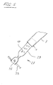
- FIG. 1 Device for perspective positioning and anchoring of a tensioning rod 1, briefly called anchoring part 3, comprises a substantially flat support plate 5 and a guide tube 7 penetrating the support plate 5 at an acute angle with an upper end 9 and a lower end 11.
- a Platen 5 could be replaced by a plastic grid or other, a plate forming body, which is penetrated by the guide tube 7 in their place.
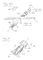
- the tube cross-section of the upper end 9 of the guide tube 7 can through a film-like cover 13 or through a plug (see Fig. 6a, 6b ) completely closed.
- the film-like cover 13 the thickness of which is a few tenths of a millimeter, is produced when spraying the anchoring part 3 directly in the injection mold; the peg-shaped cover 13a and 13b can also - be connected via film hinge with the guide tube 7 - simultaneously injected with the anchoring part 3.
- the surface of the lid 13 may lie in the plane of the end face of the upper end of the guide tube 7 or axially offset to a few millimeters within the Guide tube 7. The latter makes it possible to provide the tension rod 1 before insertion into the guide tube 7 a guide.
- the film-like cover 13 may be formed in obliquely cut end of the guide tube 7 in the same way.
- the lower end of the guide tube 7 is formed stepwise in the first embodiment of the invention, ie, the outer diameter of the guide tube 7 increases in diameter in a stepwise manner.
- the steps may be at right angles or inclined to the axis A of the guide tube 7, ie have an oval cross-section.
- thread turns or turn sections 17 are mounted at least in the lower part. In the latter comb the threaded portions 19, which are formed on the surface of the tension rod 1.
- a tension rod 1 usually a so-called Divadag rod is used (not shown).
- brackets 21 or correspondingly formed reinforcing ribs may be formed, which serve to attach the anchoring part 3 to horizontal reinforcing bars 23 of a Bodenarmtechnik (see FIG. 2 ).
- the brackets 21 may consist of two half-shell-shaped parts which are attached or integrally formed on the underside of the support plate 5.
- an anchor 27 made of metal, as shown in the DE-C2 19645759 is described and claimed.
- the armature 27 comprises a metal tube 29, in which threaded portions 17 are embossed.
- the lower end of the metal tube 29 is squeezed so that its cross section is closed at a distance from the end.
- Two anchor rods 33 and 35 are, intersecting, fixed in the metal tube 29.
- FIG. 6 In a further advantageous embodiment of the invention according to FIG. 6 are formed between the guide tube 7 and the support plate 5 on one or both sides ribs 33 or honeycombs for strength increase, which can extend to the narrow side edges of the support plate 5 out.
- This embodiment makes it possible to produce the support plate 5 is very thin and yet to obtain a high rigidity of the support plate 5 and the connection with the guide tube 7.
- markings 35 or notches running parallel to the surface of the support plate 5 are mounted in the surface of the guide tube 7.
- the markings 35 or the notches may be arranged at certain intervals, for example 1 cm, 2 cm, etc. of the surface of the support plate 5.
- the guide tube 7 may be slanted (sawn or chipped) after concreting after concreting to allow easy hand or machine troughing of the concrete surface.
- a lid 13 a can be placed even when the upper part of the guide tube 7 is separated.
- a lid 13b is inserted on its upper end, on the surface of which a bow-shaped tab 13c can be formed. This serves to be able to lift the lid 13b after concreting with a sharp tool or a reinforcing iron.
- leaning lid 13a may be provided in the surface of a dome-shaped recess which is spanned by a rod on which you can pull the lid 13a from the pipe end 7.
- the guide tubes 7 could also be in different lengths and / or already be prepared with beveled upper ends 9.
- a nut 25 is shown, which has a T-shape in cross-section and the threaded bore 25a may have different diameters, depending on the diameter of the tie rod to be anchored 1. This means that with one and the same device clamping rods 1 can be used with different diameters , Only the nut 25 must have a matching threaded hole 25a.
- the coupling sleeve 37 has at one end an outer diameter corresponding to the inner diameter of the guide tube 7.
- the other end of the connecting sleeve has an inner diameter which corresponds to the outer diameter of an extension 39 on the nut 25.
- the sleeve 37 may also have at its upper end a portion 45 with an inner diameter corresponding to the outer diameter of the guide tube 7.
- the alignment and fastening of the anchoring part 3 on a reinforcement for a concrete ceiling is extremely simple.
- the anchoring part 3 is placed with the brackets 21, on a horizontal reinforcing iron 23 and clipped to this.
- Clamps 21, 21a having different dimensions are preferably formed on the support plate 5 so that either the clamps 21 or the clamps 21a engage, depending on the thickness of the armoring iron 23.
- the support plate 5 can be fixed with binding wires to the reinforcing bars 23.
Landscapes
- Engineering & Computer Science (AREA)
- Architecture (AREA)
- Civil Engineering (AREA)
- Structural Engineering (AREA)
- Mechanical Engineering (AREA)
- Forms Removed On Construction Sites Or Auxiliary Members Thereof (AREA)
- Separation Using Semi-Permeable Membranes (AREA)
- Piles And Underground Anchors (AREA)
Priority Applications (1)
| Application Number | Priority Date | Filing Date | Title |
|---|---|---|---|
| EP15183254.0A EP2977520B1 (fr) | 2008-02-27 | 2009-02-26 | Dispositif de positionnement selon un angle precis et une position precise et ancrage d'une barre de tension |
Applications Claiming Priority (1)
| Application Number | Priority Date | Filing Date | Title |
|---|---|---|---|
| CH2882008 | 2008-02-27 |
Related Child Applications (2)
| Application Number | Title | Priority Date | Filing Date |
|---|---|---|---|
| EP15183254.0A Division EP2977520B1 (fr) | 2008-02-27 | 2009-02-26 | Dispositif de positionnement selon un angle precis et une position precise et ancrage d'une barre de tension |
| EP15183254.0A Division-Into EP2977520B1 (fr) | 2008-02-27 | 2009-02-26 | Dispositif de positionnement selon un angle precis et une position precise et ancrage d'une barre de tension |
Publications (3)
| Publication Number | Publication Date |
|---|---|
| EP2096223A2 true EP2096223A2 (fr) | 2009-09-02 |
| EP2096223A3 EP2096223A3 (fr) | 2012-06-06 |
| EP2096223B1 EP2096223B1 (fr) | 2016-06-29 |
Family
ID=40627351
Family Applications (2)
| Application Number | Title | Priority Date | Filing Date |
|---|---|---|---|
| EP15183254.0A Active EP2977520B1 (fr) | 2008-02-27 | 2009-02-26 | Dispositif de positionnement selon un angle precis et une position precise et ancrage d'une barre de tension |
| EP09405036.6A Active EP2096223B1 (fr) | 2008-02-27 | 2009-02-26 | Dispositif de positionnement et d'ancrage à position et angle précis d'une barre de tension |
Family Applications Before (1)
| Application Number | Title | Priority Date | Filing Date |
|---|---|---|---|
| EP15183254.0A Active EP2977520B1 (fr) | 2008-02-27 | 2009-02-26 | Dispositif de positionnement selon un angle precis et une position precise et ancrage d'une barre de tension |
Country Status (1)
| Country | Link |
|---|---|
| EP (2) | EP2977520B1 (fr) |
Cited By (1)
| Publication number | Priority date | Publication date | Assignee | Title |
|---|---|---|---|---|
| US20210381239A1 (en) * | 2020-02-27 | 2021-12-09 | Post Tech Manufacturing, Llc | Systems and methods for post-tensioning in concrete support systems |
Citations (2)
| Publication number | Priority date | Publication date | Assignee | Title |
|---|---|---|---|---|
| DE4234892C2 (de) | 1992-10-16 | 1995-01-05 | Karl Bisani | Anordnung zum lage- und richtungsstabilen Einbau von Verankerungsteilen in Beton |
| DE19645759C2 (de) | 1995-11-09 | 2000-11-30 | Giulio Albanese | Hülsenförmiges Verankerungselement zum Einbetten in eine Betongießmasse |
Family Cites Families (5)
| Publication number | Priority date | Publication date | Assignee | Title |
|---|---|---|---|---|
| DE19633594A1 (de) * | 1996-08-21 | 1998-02-26 | Wayss & Freytag Ag | Verankerungselement für Zugglieder |
| CH692425A5 (de) * | 1997-11-26 | 2002-06-14 | Giulio Albanese | Vorrichtung zur Verankerung eines Spannstabes in einer bewehrten Betonmasse. |
| DE59911998D1 (de) * | 1998-03-18 | 2005-06-09 | Giulio Albanese | Vorrichtung zur Verankerung eines Spannstabes in einer bewehrten Betonmasse |
| DE10258435B4 (de) * | 2002-12-13 | 2008-03-13 | Doka Industrie Gmbh | Verankerungselement |
| DE202004020274U1 (de) * | 2004-12-30 | 2005-03-24 | Betomax Kunststoff Metall | Setzvorrichtung zum winkeldefinierten Einbetonieren von Ankerrückhaltekörpern |
-
2009
- 2009-02-26 EP EP15183254.0A patent/EP2977520B1/fr active Active
- 2009-02-26 EP EP09405036.6A patent/EP2096223B1/fr active Active
Patent Citations (2)
| Publication number | Priority date | Publication date | Assignee | Title |
|---|---|---|---|---|
| DE4234892C2 (de) | 1992-10-16 | 1995-01-05 | Karl Bisani | Anordnung zum lage- und richtungsstabilen Einbau von Verankerungsteilen in Beton |
| DE19645759C2 (de) | 1995-11-09 | 2000-11-30 | Giulio Albanese | Hülsenförmiges Verankerungselement zum Einbetten in eine Betongießmasse |
Cited By (4)
| Publication number | Priority date | Publication date | Assignee | Title |
|---|---|---|---|---|
| US20210381239A1 (en) * | 2020-02-27 | 2021-12-09 | Post Tech Manufacturing, Llc | Systems and methods for post-tensioning in concrete support systems |
| US20220372761A1 (en) * | 2020-02-27 | 2022-11-24 | Post Tech Manufacturing, Llc | Systems and methods for concrete support post-tensioning |
| US11680407B2 (en) * | 2020-02-27 | 2023-06-20 | Post Tech Manufacturing, Llc | Systems and methods for post-tensioning in concrete support systems |
| US12018488B2 (en) * | 2020-02-27 | 2024-06-25 | Post Tech Manufacturing, Llc | Systems and methods for concrete support post-tensioning |
Also Published As
| Publication number | Publication date |
|---|---|
| EP2977520B1 (fr) | 2017-04-26 |
| EP2096223B1 (fr) | 2016-06-29 |
| EP2096223A3 (fr) | 2012-06-06 |
| EP2977520A1 (fr) | 2016-01-27 |
Similar Documents
| Publication | Publication Date | Title |
|---|---|---|
| EP2987595B1 (fr) | Agencement destiné à la fabrication de préfabriqués en béton doté d'au moins un rail d'ancrage intégré dans le préfabriqué en béton et procédé de fabrication de tels préfabriqués en béton | |
| EP3708730A1 (fr) | Rails d'ancrage | |
| EP0410079B1 (fr) | Coffrage de raccordement pour panneaux en béton reliés | |
| EP0554483B1 (fr) | Elément de liaison et de répartition des contraintes pour éléments de construction en béton | |
| EP2375522B1 (fr) | Boîtier d'installation à des fins électrotechniques | |
| EP3190244A1 (fr) | Douille filetée d'ancrage d'éléments de construction dans un ouvrage en béton et entretoise tubulaire | |
| EP2987924B1 (fr) | Porte-butée pour coffrage mural | |
| EP2977520B1 (fr) | Dispositif de positionnement selon un angle precis et une position precise et ancrage d'une barre de tension | |
| EP0715040A1 (fr) | Dispositif de coupe pour enrolages | |
| DE9311023U1 (de) | Einbaudose für elektrische Schalter oder Verteilerstellen | |
| DE19645759C2 (de) | Hülsenförmiges Verankerungselement zum Einbetten in eine Betongießmasse | |
| EP3754134A1 (fr) | Dispositif de serrage pour un coffrage d'angle | |
| EP3508667B1 (fr) | Procédé de raccordement d'un écarteur avec un fer de raccord, dispositif support d'écarteur et support de butée, cale et support | |
| EP0952252A1 (fr) | Coffrage pour l'encastrement d'un rail | |
| EP1847666A1 (fr) | Dispositif d'ancrage pour lier des planches de coffrage | |
| EP3263787B1 (fr) | Élément structural en béton préfabriqué, en particulier plaque en béton préfabriqué, ancrage de transport pour un tel élément en béton | |
| CH695905A5 (de) | Abstand- und Distanzhalter. | |
| EP3037682A1 (fr) | Élement de fixation destine a fixer des composants de construction sur des parois de batiment isolees | |
| EP3012468B1 (fr) | Cheville à bascule | |
| AT413723B (de) | Distanzhalterkeil | |
| DE19517233C2 (de) | Vermarkungseinrichtung zur Befestigung von Vermessungspunkten | |
| DE4100041A1 (de) | Vorrichtung zum verankern von wandplatten an einem verankerungsgrund | |
| DE29707553U1 (de) | Abstandhalter, insbesondere für Gewölbe- und Tunnelbauten | |
| WO2018078111A1 (fr) | Système de pieux | |
| DE20304390U1 (de) | Verlorener Schalungsanker |
Legal Events
| Date | Code | Title | Description |
|---|---|---|---|
| PUAI | Public reference made under article 153(3) epc to a published international application that has entered the european phase |
Free format text: ORIGINAL CODE: 0009012 |
|
| AK | Designated contracting states |
Kind code of ref document: A2 Designated state(s): AT BE BG CH CY CZ DE DK EE ES FI FR GB GR HR HU IE IS IT LI LT LU LV MC MK MT NL NO PL PT RO SE SI SK TR |
|
| AX | Request for extension of the european patent |
Extension state: AL BA RS |
|
| PUAL | Search report despatched |
Free format text: ORIGINAL CODE: 0009013 |
|
| AK | Designated contracting states |
Kind code of ref document: A3 Designated state(s): AT BE BG CH CY CZ DE DK EE ES FI FR GB GR HR HU IE IS IT LI LT LU LV MC MK MT NL NO PL PT RO SE SI SK TR |
|
| AX | Request for extension of the european patent |
Extension state: AL BA RS |
|
| RIC1 | Information provided on ipc code assigned before grant |
Ipc: E04G 21/12 20060101ALI20120427BHEP Ipc: E04C 5/12 20060101AFI20120427BHEP |
|
| 17P | Request for examination filed |
Effective date: 20121112 |
|
| AKX | Designation fees paid |
Designated state(s): AT BE BG CH CY CZ DE DK EE ES FI FR GB GR HR HU IE IS IT LI LT LU LV MC MK MT NL NO PL PT RO SE SI SK TR |
|
| 17Q | First examination report despatched |
Effective date: 20150414 |
|
| GRAP | Despatch of communication of intention to grant a patent |
Free format text: ORIGINAL CODE: EPIDOSNIGR1 |
|
| INTG | Intention to grant announced |
Effective date: 20160119 |
|
| GRAS | Grant fee paid |
Free format text: ORIGINAL CODE: EPIDOSNIGR3 |
|
| GRAA | (expected) grant |
Free format text: ORIGINAL CODE: 0009210 |
|
| AK | Designated contracting states |
Kind code of ref document: B1 Designated state(s): AT BE BG CH CY CZ DE DK EE ES FI FR GB GR HR HU IE IS IT LI LT LU LV MC MK MT NL NO PL PT RO SE SI SK TR |
|
| REG | Reference to a national code |
Ref country code: GB Ref legal event code: FG4D Free format text: NOT ENGLISH |
|
| REG | Reference to a national code |
Ref country code: CH Ref legal event code: EP |
|
| REG | Reference to a national code |
Ref country code: AT Ref legal event code: REF Ref document number: 809238 Country of ref document: AT Kind code of ref document: T Effective date: 20160715 Ref country code: CH Ref legal event code: NV Representative=s name: GACHNANG AG PATENTANWAELTE, CH |
|
| REG | Reference to a national code |
Ref country code: IE Ref legal event code: FG4D Free format text: LANGUAGE OF EP DOCUMENT: GERMAN |
|
| REG | Reference to a national code |
Ref country code: DE Ref legal event code: R096 Ref document number: 502009012745 Country of ref document: DE |
|
| REG | Reference to a national code |
Ref country code: LT Ref legal event code: MG4D |
|
| PG25 | Lapsed in a contracting state [announced via postgrant information from national office to epo] |
Ref country code: NO Free format text: LAPSE BECAUSE OF FAILURE TO SUBMIT A TRANSLATION OF THE DESCRIPTION OR TO PAY THE FEE WITHIN THE PRESCRIBED TIME-LIMIT Effective date: 20160929 Ref country code: FI Free format text: LAPSE BECAUSE OF FAILURE TO SUBMIT A TRANSLATION OF THE DESCRIPTION OR TO PAY THE FEE WITHIN THE PRESCRIBED TIME-LIMIT Effective date: 20160629 Ref country code: LT Free format text: LAPSE BECAUSE OF FAILURE TO SUBMIT A TRANSLATION OF THE DESCRIPTION OR TO PAY THE FEE WITHIN THE PRESCRIBED TIME-LIMIT Effective date: 20160629 |
|
| REG | Reference to a national code |
Ref country code: NL Ref legal event code: MP Effective date: 20160629 |
|
| PG25 | Lapsed in a contracting state [announced via postgrant information from national office to epo] |
Ref country code: SE Free format text: LAPSE BECAUSE OF FAILURE TO SUBMIT A TRANSLATION OF THE DESCRIPTION OR TO PAY THE FEE WITHIN THE PRESCRIBED TIME-LIMIT Effective date: 20160629 Ref country code: NL Free format text: LAPSE BECAUSE OF FAILURE TO SUBMIT A TRANSLATION OF THE DESCRIPTION OR TO PAY THE FEE WITHIN THE PRESCRIBED TIME-LIMIT Effective date: 20160629 Ref country code: LV Free format text: LAPSE BECAUSE OF FAILURE TO SUBMIT A TRANSLATION OF THE DESCRIPTION OR TO PAY THE FEE WITHIN THE PRESCRIBED TIME-LIMIT Effective date: 20160629 Ref country code: GR Free format text: LAPSE BECAUSE OF FAILURE TO SUBMIT A TRANSLATION OF THE DESCRIPTION OR TO PAY THE FEE WITHIN THE PRESCRIBED TIME-LIMIT Effective date: 20160930 Ref country code: HR Free format text: LAPSE BECAUSE OF FAILURE TO SUBMIT A TRANSLATION OF THE DESCRIPTION OR TO PAY THE FEE WITHIN THE PRESCRIBED TIME-LIMIT Effective date: 20160629 |
|
| PG25 | Lapsed in a contracting state [announced via postgrant information from national office to epo] |
Ref country code: EE Free format text: LAPSE BECAUSE OF FAILURE TO SUBMIT A TRANSLATION OF THE DESCRIPTION OR TO PAY THE FEE WITHIN THE PRESCRIBED TIME-LIMIT Effective date: 20160629 Ref country code: SK Free format text: LAPSE BECAUSE OF FAILURE TO SUBMIT A TRANSLATION OF THE DESCRIPTION OR TO PAY THE FEE WITHIN THE PRESCRIBED TIME-LIMIT Effective date: 20160629 Ref country code: RO Free format text: LAPSE BECAUSE OF FAILURE TO SUBMIT A TRANSLATION OF THE DESCRIPTION OR TO PAY THE FEE WITHIN THE PRESCRIBED TIME-LIMIT Effective date: 20160629 Ref country code: CZ Free format text: LAPSE BECAUSE OF FAILURE TO SUBMIT A TRANSLATION OF THE DESCRIPTION OR TO PAY THE FEE WITHIN THE PRESCRIBED TIME-LIMIT Effective date: 20160629 Ref country code: IS Free format text: LAPSE BECAUSE OF FAILURE TO SUBMIT A TRANSLATION OF THE DESCRIPTION OR TO PAY THE FEE WITHIN THE PRESCRIBED TIME-LIMIT Effective date: 20161029 Ref country code: IT Free format text: LAPSE BECAUSE OF FAILURE TO SUBMIT A TRANSLATION OF THE DESCRIPTION OR TO PAY THE FEE WITHIN THE PRESCRIBED TIME-LIMIT Effective date: 20160629 |
|
| PG25 | Lapsed in a contracting state [announced via postgrant information from national office to epo] |
Ref country code: PT Free format text: LAPSE BECAUSE OF FAILURE TO SUBMIT A TRANSLATION OF THE DESCRIPTION OR TO PAY THE FEE WITHIN THE PRESCRIBED TIME-LIMIT Effective date: 20161031 Ref country code: ES Free format text: LAPSE BECAUSE OF FAILURE TO SUBMIT A TRANSLATION OF THE DESCRIPTION OR TO PAY THE FEE WITHIN THE PRESCRIBED TIME-LIMIT Effective date: 20160629 Ref country code: PL Free format text: LAPSE BECAUSE OF FAILURE TO SUBMIT A TRANSLATION OF THE DESCRIPTION OR TO PAY THE FEE WITHIN THE PRESCRIBED TIME-LIMIT Effective date: 20160629 |
|
| REG | Reference to a national code |
Ref country code: DE Ref legal event code: R097 Ref document number: 502009012745 Country of ref document: DE |
|
| PLBE | No opposition filed within time limit |
Free format text: ORIGINAL CODE: 0009261 |
|
| STAA | Information on the status of an ep patent application or granted ep patent |
Free format text: STATUS: NO OPPOSITION FILED WITHIN TIME LIMIT |
|
| PG25 | Lapsed in a contracting state [announced via postgrant information from national office to epo] |
Ref country code: BE Free format text: LAPSE BECAUSE OF NON-PAYMENT OF DUE FEES Effective date: 20170228 Ref country code: DK Free format text: LAPSE BECAUSE OF FAILURE TO SUBMIT A TRANSLATION OF THE DESCRIPTION OR TO PAY THE FEE WITHIN THE PRESCRIBED TIME-LIMIT Effective date: 20160629 |
|
| 26N | No opposition filed |
Effective date: 20170330 |
|
| PG25 | Lapsed in a contracting state [announced via postgrant information from national office to epo] |
Ref country code: BG Free format text: LAPSE BECAUSE OF FAILURE TO SUBMIT A TRANSLATION OF THE DESCRIPTION OR TO PAY THE FEE WITHIN THE PRESCRIBED TIME-LIMIT Effective date: 20160929 Ref country code: SI Free format text: LAPSE BECAUSE OF FAILURE TO SUBMIT A TRANSLATION OF THE DESCRIPTION OR TO PAY THE FEE WITHIN THE PRESCRIBED TIME-LIMIT Effective date: 20160629 |
|
| PG25 | Lapsed in a contracting state [announced via postgrant information from national office to epo] |
Ref country code: MC Free format text: LAPSE BECAUSE OF FAILURE TO SUBMIT A TRANSLATION OF THE DESCRIPTION OR TO PAY THE FEE WITHIN THE PRESCRIBED TIME-LIMIT Effective date: 20160629 |
|
| REG | Reference to a national code |
Ref country code: IE Ref legal event code: MM4A |
|
| REG | Reference to a national code |
Ref country code: FR Ref legal event code: ST Effective date: 20171031 |
|
| PG25 | Lapsed in a contracting state [announced via postgrant information from national office to epo] |
Ref country code: LU Free format text: LAPSE BECAUSE OF NON-PAYMENT OF DUE FEES Effective date: 20170226 |
|
| PG25 | Lapsed in a contracting state [announced via postgrant information from national office to epo] |
Ref country code: FR Free format text: LAPSE BECAUSE OF NON-PAYMENT OF DUE FEES Effective date: 20170228 |
|
| REG | Reference to a national code |
Ref country code: BE Ref legal event code: MM Effective date: 20170228 |
|
| PG25 | Lapsed in a contracting state [announced via postgrant information from national office to epo] |
Ref country code: IE Free format text: LAPSE BECAUSE OF NON-PAYMENT OF DUE FEES Effective date: 20170226 |
|
| PG25 | Lapsed in a contracting state [announced via postgrant information from national office to epo] |
Ref country code: MT Free format text: LAPSE BECAUSE OF FAILURE TO SUBMIT A TRANSLATION OF THE DESCRIPTION OR TO PAY THE FEE WITHIN THE PRESCRIBED TIME-LIMIT Effective date: 20160629 |
|
| PG25 | Lapsed in a contracting state [announced via postgrant information from national office to epo] |
Ref country code: HU Free format text: LAPSE BECAUSE OF FAILURE TO SUBMIT A TRANSLATION OF THE DESCRIPTION OR TO PAY THE FEE WITHIN THE PRESCRIBED TIME-LIMIT; INVALID AB INITIO Effective date: 20090226 |
|
| PG25 | Lapsed in a contracting state [announced via postgrant information from national office to epo] |
Ref country code: CY Free format text: LAPSE BECAUSE OF NON-PAYMENT OF DUE FEES Effective date: 20160629 |
|
| PG25 | Lapsed in a contracting state [announced via postgrant information from national office to epo] |
Ref country code: MK Free format text: LAPSE BECAUSE OF FAILURE TO SUBMIT A TRANSLATION OF THE DESCRIPTION OR TO PAY THE FEE WITHIN THE PRESCRIBED TIME-LIMIT Effective date: 20160629 |
|
| PG25 | Lapsed in a contracting state [announced via postgrant information from national office to epo] |
Ref country code: TR Free format text: LAPSE BECAUSE OF FAILURE TO SUBMIT A TRANSLATION OF THE DESCRIPTION OR TO PAY THE FEE WITHIN THE PRESCRIBED TIME-LIMIT Effective date: 20160629 |
|
| REG | Reference to a national code |
Ref country code: CH Ref legal event code: PK Free format text: BERICHTIGUNGEN |
|
| REG | Reference to a national code |
Ref country code: CH Ref legal event code: U11 Free format text: ST27 STATUS EVENT CODE: U-0-0-U10-U11 (AS PROVIDED BY THE NATIONAL OFFICE) Effective date: 20260301 |
|
| PGFP | Annual fee paid to national office [announced via postgrant information from national office to epo] |
Ref country code: GB Payment date: 20260219 Year of fee payment: 18 |
|
| PGFP | Annual fee paid to national office [announced via postgrant information from national office to epo] |
Ref country code: DE Payment date: 20260217 Year of fee payment: 18 |
|
| PGFP | Annual fee paid to national office [announced via postgrant information from national office to epo] |
Ref country code: AT Payment date: 20260216 Year of fee payment: 18 |
|
| PGFP | Annual fee paid to national office [announced via postgrant information from national office to epo] |
Ref country code: CH Payment date: 20260301 Year of fee payment: 18 |