EP2096234A1 - Eine Klemmbacke zur Montage einer Bahn von Deckplatten - Google Patents
Eine Klemmbacke zur Montage einer Bahn von Deckplatten Download PDFInfo
- Publication number
- EP2096234A1 EP2096234A1 EP08101991A EP08101991A EP2096234A1 EP 2096234 A1 EP2096234 A1 EP 2096234A1 EP 08101991 A EP08101991 A EP 08101991A EP 08101991 A EP08101991 A EP 08101991A EP 2096234 A1 EP2096234 A1 EP 2096234A1
- Authority
- EP
- European Patent Office
- Prior art keywords
- bar
- slide
- jaw
- deck
- jaw clamp
- Prior art date
- Legal status (The legal status is an assumption and is not a legal conclusion. Google has not performed a legal analysis and makes no representation as to the accuracy of the status listed.)
- Withdrawn
Links
Images
Classifications
-
- E—FIXED CONSTRUCTIONS
- E04—BUILDING
- E04F—FINISHING WORK ON BUILDINGS, e.g. STAIRS, FLOORS
- E04F21/00—Implements for finishing work on buildings
- E04F21/20—Implements for finishing work on buildings for laying flooring
- E04F21/22—Implements for finishing work on buildings for laying flooring of single elements, e.g. flooring cramps ; flexible webs
-
- B—PERFORMING OPERATIONS; TRANSPORTING
- B25—HAND TOOLS; PORTABLE POWER-DRIVEN TOOLS; MANIPULATORS
- B25B—TOOLS OR BENCH DEVICES NOT OTHERWISE PROVIDED FOR, FOR FASTENING, CONNECTING, DISENGAGING, OR HOLDING
- B25B5/00—Clamps
- B25B5/06—Arrangements for positively actuating jaws
- B25B5/068—Arrangements for positively actuating jaws with at least one jaw sliding along a bar
Definitions
- the invention relates to a jaw clamp for moving an unsecured board transversely on a underlying deck support to a predetermined position on the deck support and for straightening warped or bowed deck boards on the deck support.
- the jaw clamp is comprising a first jaw attached to a bar, a second jaw attached to a slide on the bar, a handle lever which pivotally is mounted upon a transverse pivot on the slide and partly is extending into a cavity formed in the slide, a spring loaded ring which is placed in said cavity and is encompassing the bar, and a pressure foot on the handle for jamming the ring tight to the bar by exerting a pressure upon the ring when pivoting the handle lever.
- Decks consisting of a number of boards are used as floors in for example buildings and terraces where the boards are attached to a number of underlying joists.
- the boards are for some applications abutting each other along their edges while there in other applications is a distance between the edges of the boards.
- Another problem consists in that warped or bowed boards are difficult or impossible to straighten out manually during assembling of the deck.
- US Publication No. 7144004 thus proposes a jaw clamp for clamping the boards of a deck together.
- the jaws of the clamp are screwed together by manually rotation a crank positioned in the same level as the deck. The operator therefore needs to stoop far down for being able to operate this known jaw clamp or need to perform the assembling operations on knees.
- US Publication No.5190266 discloses an articulating assembly for straightening and installing of deck boards.
- the assembly has a generally vertical first arm member pivotally mounted to a pivot on a generally horizontal second arm member with a first jaw at on end and bearings for the pivot at the other end.
- the first arm functions as a handle equipped with a second jaw arranged for during operation engaging the edge of deck board to be straightened.
- the assembly can be operated by the operator in standing position.
- the construction of the assembly allows however only limited mutual movements of the two jaws implying that only little warped or bowed boards can be straightened sufficiently out and that a not secured board only can be moved a little and often not a sufficient distance against a secured board.
- novel and unique features of the invention whereby these features are achieved consist in the fact that the handle lever is divided up into a first separate lever arm extending into the slide and a second separate lever arm extending outwards from the slide, that each of the two separate arms pivotally is mounted upon the pivot, and that the two separate arms have a first and second coupling part, respectively arranged for coupling the two arms together in more mutual angle positions.
- the second lever arm is, in the operative position of the jaw clamp, more or less upright so that the operator in standing position will be able to operate the jaw clamp by turning the second lever arm about the common pivot of the two lever arms by using one hand only.
- the working position of the second lever arm easily can be adjusted to a position well suited for the actual operator since the two lever arms can be coupled together in more angular positions.
- the first coupling part on the first lever arm can, in an advantageous embodiment of the invention, consist of a disc with a number of incisions while the second coupling part on the second lever arm can consist of a spring loaded pin fitting into each of the incisions in the disc whereby the pin displaceable is mounted to the separate lever arm so that the pin optionally can engage or disengage the respective incision.
- a jaw clamp according to the invention generally denounced with the numeral 1.
- the jaw clamp comprises a first jaw 2 releasable attached to an end part of a bar 3, a second jaw 4 fixed to a slide 5 on the bar and a handle lever 6 for manually activating the jaw clamp.
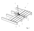
- the jaw clamp 1 is in fig. 1 used for assembling a deck 7 supported by four joists 8 and a number of deck boards of which four boards 9 already are secured to the joists by means of fasteners 10 while one board 11 still is unsecured.
- the first jaw 2 is engaging an edge of the first board 9 in the row of secured boards 9 while the second jaw 4 is engaging an edge of the unsecured board 11.
- the second jaw 4 is relatively broad for easily and securely being able to displace the unsecured board parallel to the secured boards.
- the boards of the deck can be secured to the joists in positions where they, as seen in fig. 1 , are separated with a space in between or, as seen in fig. 2 , are abutting each other.
- the first jaw 2 has a hook 12 thin enough to fit into the space between each of two boards seen in fig. 1 so that the first jaw can engage an edge of each of the secured boards (not shown).
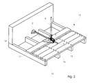
- Fig. 2 shows the jaw clamp 1 shown in fig. 1 used for assembling another deck 13 supported by four joists 14 and a number of deck boards of which three boards 15 already are secured to the joists by means of fasteners 16 while one board 17 still is unsecured.
- the boards are, as can be seen, abutting each other in their secured positions.
- the first jaw 2 has in this case been removed from the end part of the bar shown in fig. 1 for in fig. 2 releasable to be attached to the opposite end part of the bar.
- the first jaw is in this position leaning against a wall 18 while the second jaw 4 is engaging the unsecured board 17.
- the second jaw 4 attached to the slide therefore is drawing the unsecured board 17 to a predetermined position for being fastened here to the joists 14 like the already secured boards 15.
- the mode of operating the jaw clamp of the invention is especially useful when drawing an unsecured board placed close to a wall along the joists, e.g. the board closest to the wall.
- the operator can easily operate the jaw clamp in a comfortable standing position and with one hand only since the handle lever is long and presents a large gearing.
- the jaw clamp is anyhow able to displace a board a relatively large distance along the joists by only repeating the turning of the handle lever a number of times.
- the large gearing also implies that the operator with minimal effort can straighten warped or bowed boards on the deck.
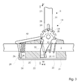
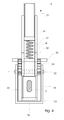
- the slide 6 itself comprises a casing 20 and a first and second sliding bushing 21 and 22 which slidingly are mounted on the bar 3.
- the two sliding bushings are preferably made of plastic or metal.
- a first and second cavity 23 and 24 are formed in the casing 20.
- a first tilted plate formed ring 25, which is encompassing the bar 3, is placed in the first cavity 23 and a second tilted plate formed ring 26, which is encompassing the bar 3, is placed in the second cavity 24.
- a first compression spring 27 is acting between the first sliding bushing 21 and the first plate formed ring 25 and a second compression spring 28 is acting between the second sliding bushing 22 and the second plate formed ring 26.
- the first plate formed ring 25 is, at the top seen in the figures, abutting the second sliding bushing 22 while the second plate formed ring 26 is abutting a stop 29 on the casing.
- the bar 3 and the two plate formed rings 25 and 26 are preferably made of hardened steel.
- the handle lever 20 is divided up into a first separate lever arm 30 extending into the first cavity 23 in the casing 20 and a second separate lever arm 31 extending outwards from the slide 5. Both of the two separate lever arms are pivotally mounted upon a common pivot 32 arranged on the casing 20.
- the first separate lever arm 30 consists of two pieces of plate 33, which each is formed with a semicircular coupling disc 34 with, in this case, seven incisions 35 and which mutual is connected with a rod 36 forming a pressure foot.
- An end part of the second separate lever arm 31 is formed as two flat bars 37 having each a slit 38 for displaceable accommodating a traverse pin 39 which fits into each of the incisions 35 in the semicircular coupling discs 34 of the first separate lever arm 30.
- a compression spring 40 acting between the traverse pin 39 and a support 41 for the spring.
- This construction makes it advantageously possible for the actual operator to set the handle lever 6 of the jaw clamp in a position in relating to the slide 5 in which said operator finds that he in the best possible way can carry out the assembling operation of a deck of boards. Another operator might set the handle lever in another position convenient for him.
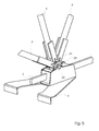
- Fig. 5 shows the jaw clamp of the invention with the handle lever 6 placed in three different positions in relating to slide 5. Seven different positions are in this case possible.
- An operator can easily set the handle lever 6 in desired position in relating to the slide 5 by manually displacing the traverse pin 39 upwards seen in the figures in the slit 38 against the elastic force of the compression spring 40 so that the traverse pin 39 is disengaging the respective incision 35 in the semicircular coupling discs 34 of the first separate lever arm 30, then turning the handle lever and letting the elastic force of the compression spring 40 forcing the traverse pin 39 into engagement with a suitable other incision 35.
- the pressure foot 36 will by turning the rigid handle lever 6 with a force swing about the pivot 32 whereby the pressure foot 36 will act upon the first plate formed ring 25 with a pressure which will tilt the first plate formed ring 25 further and thereby jam it tight to the bar.
- the second plate formed ring 26 cannot participate in the relatively movement of the bar 6 since it is kept in position in relation to the slide 5 by the second compression spring 28 and the stop 29 on the casing 20. The bar 6 therefore will be pulled through the second plate formed ring 26.
- the second compression spring 28 and the stop 29 will however jam the second plate formed ring 28 tight to the bar 6 when stopping to turn the handle lever with a force or to turn it into the opposite direction thereby securing the position of the bar 6 in relating to the slide 5.
- the secured position can easily be released by means of a press onto a pedal 42 attached to the top of the second plate formed ring 26.
- the press can comfortably be exercised by depressing the pedal with a foot.
Landscapes
- Engineering & Computer Science (AREA)
- Architecture (AREA)
- Mechanical Engineering (AREA)
- Civil Engineering (AREA)
- Structural Engineering (AREA)
- Gripping Jigs, Holding Jigs, And Positioning Jigs (AREA)
Priority Applications (2)
| Application Number | Priority Date | Filing Date | Title |
|---|---|---|---|
| EP08101991A EP2096234A1 (de) | 2008-02-26 | 2008-02-26 | Eine Klemmbacke zur Montage einer Bahn von Deckplatten |
| PCT/EP2009/052254 WO2009106556A1 (en) | 2008-02-26 | 2009-02-26 | A jaw clamp for assembling a deck of deck boards |
Applications Claiming Priority (1)
| Application Number | Priority Date | Filing Date | Title |
|---|---|---|---|
| EP08101991A EP2096234A1 (de) | 2008-02-26 | 2008-02-26 | Eine Klemmbacke zur Montage einer Bahn von Deckplatten |
Publications (1)
| Publication Number | Publication Date |
|---|---|
| EP2096234A1 true EP2096234A1 (de) | 2009-09-02 |
Family
ID=39639312
Family Applications (1)
| Application Number | Title | Priority Date | Filing Date |
|---|---|---|---|
| EP08101991A Withdrawn EP2096234A1 (de) | 2008-02-26 | 2008-02-26 | Eine Klemmbacke zur Montage einer Bahn von Deckplatten |
Country Status (2)
| Country | Link |
|---|---|
| EP (1) | EP2096234A1 (de) |
| WO (1) | WO2009106556A1 (de) |
Cited By (3)
| Publication number | Priority date | Publication date | Assignee | Title |
|---|---|---|---|---|
| DE202010000256U1 (de) | 2010-02-25 | 2011-08-23 | Wolfcraft Gmbh | Montagezwinge zum Verlegen von Terrassenboden |
| CN104541002A (zh) * | 2012-05-02 | 2015-04-22 | 可耐福石膏两合公司 | 用于制造干结构壁的方法 |
| CN110565920A (zh) * | 2019-10-09 | 2019-12-13 | 广东博智林机器人有限公司 | 一种地板安装工装及采用该工装的地板安装机器人 |
Citations (9)
| Publication number | Priority date | Publication date | Assignee | Title |
|---|---|---|---|---|
| DE470869C (de) * | 1929-01-31 | Schuermann & Rickert | Dielenpresse | |
| US4926722A (en) * | 1988-08-19 | 1990-05-22 | Petersen Manufacturing Co., Inc. | Quick-action bar clamp |
| US5190266A (en) | 1992-04-23 | 1993-03-02 | John Barrera | Decking clamp and spacer |
| DE9309877U1 (de) * | 1993-07-02 | 1994-11-03 | Maltitz, Friedrich, 09355 Gersdorf | Spannvorrichtung zum Verlegen von Dielenbrettern o.dgl. |
| US5527014A (en) | 1994-11-10 | 1996-06-18 | Bracewell; Michael | Deck board pushing and clamping device |
| DE29615868U1 (de) * | 1996-09-11 | 1997-01-02 | Chang, Ching-Tsung, Taichung | Klemmanordnung |
| US6086048A (en) * | 1998-09-11 | 2000-07-11 | Owen; William D. | Board puller |
| US7144004B1 (en) | 2004-07-26 | 2006-12-05 | Adjustable Clamp Co. | Clamp jaw for restricted spaces |
| WO2007128044A1 (en) * | 2006-05-05 | 2007-11-15 | Frederick Joseph Campion Nash | Apparatus for positioning and then fixing floorboards relative to an underlying substrate |
-
2008
- 2008-02-26 EP EP08101991A patent/EP2096234A1/de not_active Withdrawn
-
2009
- 2009-02-26 WO PCT/EP2009/052254 patent/WO2009106556A1/en not_active Ceased
Patent Citations (9)
| Publication number | Priority date | Publication date | Assignee | Title |
|---|---|---|---|---|
| DE470869C (de) * | 1929-01-31 | Schuermann & Rickert | Dielenpresse | |
| US4926722A (en) * | 1988-08-19 | 1990-05-22 | Petersen Manufacturing Co., Inc. | Quick-action bar clamp |
| US5190266A (en) | 1992-04-23 | 1993-03-02 | John Barrera | Decking clamp and spacer |
| DE9309877U1 (de) * | 1993-07-02 | 1994-11-03 | Maltitz, Friedrich, 09355 Gersdorf | Spannvorrichtung zum Verlegen von Dielenbrettern o.dgl. |
| US5527014A (en) | 1994-11-10 | 1996-06-18 | Bracewell; Michael | Deck board pushing and clamping device |
| DE29615868U1 (de) * | 1996-09-11 | 1997-01-02 | Chang, Ching-Tsung, Taichung | Klemmanordnung |
| US6086048A (en) * | 1998-09-11 | 2000-07-11 | Owen; William D. | Board puller |
| US7144004B1 (en) | 2004-07-26 | 2006-12-05 | Adjustable Clamp Co. | Clamp jaw for restricted spaces |
| WO2007128044A1 (en) * | 2006-05-05 | 2007-11-15 | Frederick Joseph Campion Nash | Apparatus for positioning and then fixing floorboards relative to an underlying substrate |
Cited By (3)
| Publication number | Priority date | Publication date | Assignee | Title |
|---|---|---|---|---|
| DE202010000256U1 (de) | 2010-02-25 | 2011-08-23 | Wolfcraft Gmbh | Montagezwinge zum Verlegen von Terrassenboden |
| CN104541002A (zh) * | 2012-05-02 | 2015-04-22 | 可耐福石膏两合公司 | 用于制造干结构壁的方法 |
| CN110565920A (zh) * | 2019-10-09 | 2019-12-13 | 广东博智林机器人有限公司 | 一种地板安装工装及采用该工装的地板安装机器人 |
Also Published As
| Publication number | Publication date |
|---|---|
| WO2009106556A1 (en) | 2009-09-03 |
Similar Documents
| Publication | Publication Date | Title |
|---|---|---|
| JP4083713B2 (ja) | 改良に係るクランプ装置 | |
| US7066457B2 (en) | Apparatus for securing a workpiece | |
| US7798478B2 (en) | Parallel clamp and accessories therefor | |
| US5190266A (en) | Decking clamp and spacer | |
| US10011005B2 (en) | Bar clamp | |
| US8601909B2 (en) | Deck tool | |
| EP2113327A1 (de) | Schraubstockanordnung und Tischkreissäge | |
| US11554473B2 (en) | Lowering mechanism for hand held jacking tool | |
| EP2096234A1 (de) | Eine Klemmbacke zur Montage einer Bahn von Deckplatten | |
| US7168181B2 (en) | Hand tool apparatus and method | |
| US8109494B1 (en) | Workholding apparatus having a movable jaw member | |
| US20100095823A1 (en) | Bench cutter | |
| US7581477B2 (en) | Saw table and clamping mechanism therefor | |
| CA2599513A1 (en) | Tool for installing large sheets of material on a ceiling and method | |
| US20070222130A1 (en) | Quick release mechanism | |
| US4729552A (en) | Vertical vise | |
| JP4209120B2 (ja) | 切断機 | |
| EP0897881A1 (de) | Hubgerät | |
| CN2290437Y (zh) | 具有可倾斜工作台及对选定角度位置止挡的曲线锯机 | |
| US20050247019A1 (en) | Adjustable joist gripper | |
| US8307557B1 (en) | Foot operated cutter | |
| JP2012086503A (ja) | のこぎり補助具 | |
| US8322254B2 (en) | Plank installation tool with infinitesimal joist width adjustment | |
| US20260103364A1 (en) | Friction lock bar jack for construction | |
| EP1757394A1 (de) | Bewegliche Platte für einen Werkstücktisch |
Legal Events
| Date | Code | Title | Description |
|---|---|---|---|
| PUAI | Public reference made under article 153(3) epc to a published international application that has entered the european phase |
Free format text: ORIGINAL CODE: 0009012 |
|
| AK | Designated contracting states |
Kind code of ref document: A1 Designated state(s): AT BE BG CH CY CZ DE DK EE ES FI FR GB GR HR HU IE IS IT LI LT LU LV MC MT NL NO PL PT RO SE SI SK TR |
|
| AX | Request for extension of the european patent |
Extension state: AL BA MK |
|
| 17P | Request for examination filed |
Effective date: 20100302 |
|
| AKX | Designation fees paid |
Designated state(s): AT BE BG CH CY CZ DE DK EE ES FI FR GB GR HR HU IE IS IT LI LT LU LV MC MT NL NO PL PT RO SE SI SK TR |
|
| 17Q | First examination report despatched |
Effective date: 20100604 |
|
| STAA | Information on the status of an ep patent application or granted ep patent |
Free format text: STATUS: THE APPLICATION IS DEEMED TO BE WITHDRAWN |
|
| 18D | Application deemed to be withdrawn |
Effective date: 20101015 |