EP2096281A1 - Verbrennungsmotorsteuerungsverfahren, Verbrennungsmotorsystem und entsprechendes Computerprogrammprodukt - Google Patents
Verbrennungsmotorsteuerungsverfahren, Verbrennungsmotorsystem und entsprechendes Computerprogrammprodukt Download PDFInfo
- Publication number
- EP2096281A1 EP2096281A1 EP09002673A EP09002673A EP2096281A1 EP 2096281 A1 EP2096281 A1 EP 2096281A1 EP 09002673 A EP09002673 A EP 09002673A EP 09002673 A EP09002673 A EP 09002673A EP 2096281 A1 EP2096281 A1 EP 2096281A1
- Authority
- EP
- European Patent Office
- Prior art keywords
- air
- cylinder
- intake valve
- amount
- inducted
- Prior art date
- Legal status (The legal status is an assumption and is not a legal conclusion. Google has not performed a legal analysis and makes no representation as to the accuracy of the status listed.)
- Granted
Links
- 238000002485 combustion reaction Methods 0.000 title claims abstract description 96
- 238000000034 method Methods 0.000 title claims abstract description 65
- 238000004590 computer program Methods 0.000 title claims description 4
- 230000007246 mechanism Effects 0.000 claims description 54
- 230000003247 decreasing effect Effects 0.000 claims description 35
- 230000006835 compression Effects 0.000 claims description 31
- 238000007906 compression Methods 0.000 claims description 31
- 230000008859 change Effects 0.000 claims description 13
- 230000002159 abnormal effect Effects 0.000 description 46
- 239000000446 fuel Substances 0.000 description 29
- 239000007789 gas Substances 0.000 description 29
- 230000007704 transition Effects 0.000 description 24
- 230000007423 decrease Effects 0.000 description 13
- 230000008569 process Effects 0.000 description 10
- 238000005086 pumping Methods 0.000 description 10
- 238000002347 injection Methods 0.000 description 7
- 239000007924 injection Substances 0.000 description 7
- 239000000203 mixture Substances 0.000 description 7
- 230000004044 response Effects 0.000 description 6
- 230000005540 biological transmission Effects 0.000 description 4
- 230000003197 catalytic effect Effects 0.000 description 4
- 230000002706 hydrostatic effect Effects 0.000 description 4
- 230000001052 transient effect Effects 0.000 description 4
- 239000003054 catalyst Substances 0.000 description 3
- 230000006872 improvement Effects 0.000 description 3
- 230000000979 retarding effect Effects 0.000 description 3
- QVGXLLKOCUKJST-UHFFFAOYSA-N atomic oxygen Chemical compound [O] QVGXLLKOCUKJST-UHFFFAOYSA-N 0.000 description 2
- 230000008901 benefit Effects 0.000 description 2
- 230000000903 blocking effect Effects 0.000 description 2
- 239000007788 liquid Substances 0.000 description 2
- 239000001301 oxygen Substances 0.000 description 2
- 229910052760 oxygen Inorganic materials 0.000 description 2
- 230000037361 pathway Effects 0.000 description 2
- 238000004064 recycling Methods 0.000 description 2
- 230000009467 reduction Effects 0.000 description 2
- 230000033228 biological regulation Effects 0.000 description 1
- 239000000470 constituent Substances 0.000 description 1
- 230000008878 coupling Effects 0.000 description 1
- 238000010168 coupling process Methods 0.000 description 1
- 238000005859 coupling reaction Methods 0.000 description 1
- 230000001419 dependent effect Effects 0.000 description 1
- 230000000881 depressing effect Effects 0.000 description 1
- 238000001514 detection method Methods 0.000 description 1
- 238000011161 development Methods 0.000 description 1
- 230000018109 developmental process Effects 0.000 description 1
- 238000010586 diagram Methods 0.000 description 1
- 239000002828 fuel tank Substances 0.000 description 1
- 238000009434 installation Methods 0.000 description 1
- 230000004048 modification Effects 0.000 description 1
- 238000012986 modification Methods 0.000 description 1
- 239000010705 motor oil Substances 0.000 description 1
- 230000010355 oscillation Effects 0.000 description 1
- 230000003647 oxidation Effects 0.000 description 1
- 238000007254 oxidation reaction Methods 0.000 description 1
- 230000002265 prevention Effects 0.000 description 1
Images






Classifications
-
- F—MECHANICAL ENGINEERING; LIGHTING; HEATING; WEAPONS; BLASTING
- F02—COMBUSTION ENGINES; HOT-GAS OR COMBUSTION-PRODUCT ENGINE PLANTS
- F02D—CONTROLLING COMBUSTION ENGINES
- F02D13/00—Controlling the engine output power by varying inlet or exhaust valve operating characteristics, e.g. timing
- F02D13/02—Controlling the engine output power by varying inlet or exhaust valve operating characteristics, e.g. timing during engine operation
- F02D13/0223—Variable control of the intake valves only
- F02D13/0226—Variable control of the intake valves only changing valve lift or valve lift and timing
- F02D13/023—Variable control of the intake valves only changing valve lift or valve lift and timing the change of valve timing is caused by the change in valve lift, i.e. both valve lift and timing are functionally related
-
- F—MECHANICAL ENGINEERING; LIGHTING; HEATING; WEAPONS; BLASTING
- F02—COMBUSTION ENGINES; HOT-GAS OR COMBUSTION-PRODUCT ENGINE PLANTS
- F02D—CONTROLLING COMBUSTION ENGINES
- F02D41/00—Electrical control of supply of combustible mixture or its constituents
- F02D41/0002—Controlling intake air
-
- F—MECHANICAL ENGINEERING; LIGHTING; HEATING; WEAPONS; BLASTING
- F02—COMBUSTION ENGINES; HOT-GAS OR COMBUSTION-PRODUCT ENGINE PLANTS
- F02D—CONTROLLING COMBUSTION ENGINES
- F02D41/00—Electrical control of supply of combustible mixture or its constituents
- F02D41/0025—Controlling engines characterised by use of non-liquid fuels, pluralities of fuels, or non-fuel substances added to the combustible mixtures
- F02D41/0047—Controlling exhaust gas recirculation [EGR]
- F02D41/006—Controlling exhaust gas recirculation [EGR] using internal EGR
-
- F—MECHANICAL ENGINEERING; LIGHTING; HEATING; WEAPONS; BLASTING
- F02—COMBUSTION ENGINES; HOT-GAS OR COMBUSTION-PRODUCT ENGINE PLANTS
- F02D—CONTROLLING COMBUSTION ENGINES
- F02D41/00—Electrical control of supply of combustible mixture or its constituents
- F02D41/0025—Controlling engines characterised by use of non-liquid fuels, pluralities of fuels, or non-fuel substances added to the combustible mixtures
- F02D41/0047—Controlling exhaust gas recirculation [EGR]
- F02D41/0065—Specific aspects of external EGR control
-
- F—MECHANICAL ENGINEERING; LIGHTING; HEATING; WEAPONS; BLASTING
- F01—MACHINES OR ENGINES IN GENERAL; ENGINE PLANTS IN GENERAL; STEAM ENGINES
- F01L—CYCLICALLY OPERATING VALVES FOR MACHINES OR ENGINES
- F01L2820/00—Details on specific features characterising valve gear arrangements
- F01L2820/03—Auxiliary actuators
- F01L2820/032—Electric motors
-
- F—MECHANICAL ENGINEERING; LIGHTING; HEATING; WEAPONS; BLASTING
- F02—COMBUSTION ENGINES; HOT-GAS OR COMBUSTION-PRODUCT ENGINE PLANTS
- F02D—CONTROLLING COMBUSTION ENGINES
- F02D41/00—Electrical control of supply of combustible mixture or its constituents
- F02D41/0002—Controlling intake air
- F02D2041/002—Controlling intake air by simultaneous control of throttle and variable valve actuation
-
- Y—GENERAL TAGGING OF NEW TECHNOLOGICAL DEVELOPMENTS; GENERAL TAGGING OF CROSS-SECTIONAL TECHNOLOGIES SPANNING OVER SEVERAL SECTIONS OF THE IPC; TECHNICAL SUBJECTS COVERED BY FORMER USPC CROSS-REFERENCE ART COLLECTIONS [XRACs] AND DIGESTS
- Y02—TECHNOLOGIES OR APPLICATIONS FOR MITIGATION OR ADAPTATION AGAINST CLIMATE CHANGE
- Y02T—CLIMATE CHANGE MITIGATION TECHNOLOGIES RELATED TO TRANSPORTATION
- Y02T10/00—Road transport of goods or passengers
- Y02T10/10—Internal combustion engine [ICE] based vehicles
- Y02T10/12—Improving ICE efficiencies
-
- Y—GENERAL TAGGING OF NEW TECHNOLOGICAL DEVELOPMENTS; GENERAL TAGGING OF CROSS-SECTIONAL TECHNOLOGIES SPANNING OVER SEVERAL SECTIONS OF THE IPC; TECHNICAL SUBJECTS COVERED BY FORMER USPC CROSS-REFERENCE ART COLLECTIONS [XRACs] AND DIGESTS
- Y02—TECHNOLOGIES OR APPLICATIONS FOR MITIGATION OR ADAPTATION AGAINST CLIMATE CHANGE
- Y02T—CLIMATE CHANGE MITIGATION TECHNOLOGIES RELATED TO TRANSPORTATION
- Y02T10/00—Road transport of goods or passengers
- Y02T10/10—Internal combustion engine [ICE] based vehicles
- Y02T10/40—Engine management systems
Definitions
- the present description relates to a method of controlling an internal combustion engine. More particularly, the present description pertains to a method for controlling a closing timing for an intake valve, and specifically to a method for selecting a closing timing of an intake valve applicable to an internal combustion engine with a relatively high compression ratio.
- an intake air inertia increases as engine speed increases. Accordingly, if valve lift is equal to, or greater than, a predetermined value that is determined by air flow, when an intake valve is closed at a predetermined timing that is retarded in accordance with engine speed, an amount of air charge in an engine cylinder will become maximum. And, an amount of air charge in an engine cylinder decreases as a difference between an intake valve closing timing and the predetermined timing that is retarded in accordance with engine speed increases, in other words, as an intake valve is closed earlier or later than the predetermined timing.
- a cam-driven type variable valve operation system described in the above reference is implemented according to this principle and controlled such that a valve lift increases as a desired amount of air charge in each of the engine cylinders increases, and an intake valve closing timing is retarded as a valve lift increases. Accordingly, an amount of air charge in an engine cylinder can be controlled to be a desired amount while maintaining a high intake passage pressure.
- a level of in-cylinder pressure is substantially equal to a pressure in an intake passage and an in-crank case pressure is substantially equal to an atmosphere pressure.
- a geometric expansion ratio is defined as a ratio of a cylinder volume with which a piston is positioned at top dead center to a cylinder volume with which a piston is positioned at bottom dead center. Accordingly, as an expansion ratio is increased, energy of an air-fuel mixture is converted with higher efficiency by piston work, resulting in improving engine operating efficiency. However, this method increases a compression ratio too.
- an engine operating efficiency can be improved by increasing an expansion ratio while solving issues due to the higher compression ratio.
- variable valve operating system which is configured to cyclically open and close said intake valve by mechanically converting a rotational motion of a crankshaft of an internal combustion engine into a reciprocating motion of the intake valve (such as a variable valve operating system described in the first reference) is used, it is not always easy to balance an improvement of output using a higher compression ratio with regulation of abnormal combustion such as pre-ignition, knocking, etc.
- variable valve operation system described in the first reference is configured to close an intake valve later as a desired amount of air to be inducted into an engine cylinder is greater while maintaining an amount of change for an intake valve opening timing relatively small.
- An intake valve is closed at a timing, which is before a maximum charge closing timing with which an amount of air inducted into an engine cylinder is maximized at a given engine speed during a cylinder cycle. And, by retarding an intake valve closing timing, an amount of air to be inducted into the cylinder is increased.
- an intake valve closing timing with which an amount of air inducted into a cylinder is maximized at a given engine speed during a cylinder cycle, is retarded as an engine speed is greater. Further still, the need to limit desired intake valve closing timing toward an advanced side is decreased as an engine speed increases because higher engine speed can enhance fluidity of air-fuel mixture in a cylinder and the possibility of abnormal combustion is decreased. Accordingly, desired intake valve closing timing is retarded at a faster rate as an engine speed is greater.
- a variable valve operation system where an intake valve closing timing is mechanically retarded relative to a phase of a crank shaft, such as in the first reference, has a limitation in its response.
- This limitation may cause the intake valve to close earlier than the desired intake valve closing timing, which may result in decreasing the amount of air charge in a cylinder. Thereby, there is insufficient air-fuel mixture in a cylinder due to lack of air charge, and desired output cannot be obtained when the air-fuel mixture is combusted.
- One aspect of the present description includes a method of controlling an internal combustion engine having a cylinder or a plurality of cylinders each accommodating a piston which reciprocates therein, and defining a combustion chamber, an air intake passage through which air is inducted into said cylinder, and an intake valve capable of shutting off air flowing into said cylinder from said air intake passage, the method comprising: closing said intake valve at a timing in a first range, i.e.
- an angular range of a rotation of a crankshaft in a specific stroke which is before a maximum charge closing timing with which an amount of air inducted into said cylinder from said air intake passage would be maximized at a given engine speed during a cylinder cycle when a desired amount of air to be inducted into said cylinder is less than or equal to a predetermined air amount at the given engine speed; and closing said intake valve at a timing in a second range, i.e. an angular range of a rotation of the crankshaft in a specific stroke, which is after said maximum charge closing timing and separated from said first range during a cylinder cycle when a desired amount of air to be inducted into said cylinder is greater than said predetermined air amount at the given engine speed.
- an intake valve is closed at a timing in a first range, for example before a bottom dead center of intake stroke.
- this operation is referred to as "earlier closing operation”.
- a desired amount of air to be inducted into said cylinder is greater than a second predetermined air amount
- an intake valve is closed at a timing in a second range that is later than the first range and separated from the first range, for example after the bottom dead center of intake stroke.
- this operation is referred to as "later closing operation”.
- variable valve operation system configured to close an intake valve later as a desired amount of air to be inducted in a cylinder increases while substantially maintaining an intake valve opening timing is adopted.
- an engine is operated in an operation range where the desired amount of air to be inducted into a cylinder is relatively small, an engine is operated with a small valve lift suitable for the desired amount of air to be inducted into a cylinder by closing the intake valve earlier, thereby suppressing a mechanical loss caused by the valve operation.
- the engine is operated in an operation range where the desired amount of air to be inducted into a cylinder is relatively large, the engine is operated with a large valve lift suitable for the desired amount of air to be inducted into the cylinder by closing the intake valve later, thereby suppressing possibility of abnormal combustion (such as pre-ignition) while inducting the desired amount of air into the cylinder.
- An intake valve closing timing leading to a given amount of air to be inducted into a cylinder, is retarded as an engine speed increases, due to intake air inertia. Accordingly, by setting the intake valve closing timing in the second range when engine speed is low, a frequency of the intake valve closing timing residing in an intermediate range located between the first range and the second range when engine speed is increasing under high-load condition is reduced.
- a pressure in the intake passage might be decreased in order to prevent abnormal combustion due to excessive charge in the intermediate range
- a frequency of decreasing the pressure in the intake passage is reduced thereby reducing a pump loss
- this method can improve an engine operating efficiency with an increased expansion ratio while avoiding issues associated with increasing the compression ratio of an engine.
- the first range is before the intake bottom dead center during the cylinder cycle and the second range is after the intake bottom dead center during the cylinder cycle.
- the expansion ratio can be increased with a range capable of avoiding abnormal combustion (e.g., pre-ignition) thereby improving engine operating efficiency, especially in low-speed operating condition where pre-ignition may occur.
- abnormal combustion e.g., pre-ignition
- this method further comprises decreasing the pressure of air inducted into the cylinder as the desired amount of air to be inducted into the cylinder increases, when the desired air amount is less than or equal to the predetermined air amount at the given engine speed.
- the pressure of air inducted into said cylinder will be decreased before the desired amount of air to be inducted into said cylinder becomes greater than the predetermined air amount. Therefore, even when the intake valve is closed within the intermediate range (positioned between the first range and the second range) such that it is in the process of changing from the earlier closing operation to the later closing operation, the pressure of air inducted into said cylinder has already been decreased at that timing, which can avoid abnormal combustion, such as pre-ignition.
- this method further comprises closing the intake valve later during the cylinder cycle as the engine speed increases.
- This method can maintain air flow at an appropriate level in response to an intake air inertia that is increased as the engine speed is increased, and maintain a preferable amount of air charge over a broader operating range.
- this method further comprises closing the intake valve earlier during the cylinder cycle as the desired amount of air to be inducted into the cylinder increases, when the desired air amount is greater than the predetermined air amount at the given engine speed.
- This method can achieve the desired amount of air charge over a broader operating range without pump loss because when the desired amount of air to be inducted into a cylinder is maximum, the intake valve will close at a timing with which an amount of air inducted into a cylinder from an air intake passage is maximized.
- the pressure of air inducted into said cylinder can be substantially maintained when the desired air amount is greater than the predetermined air amount at the given engine speed.
- this method may further comprise increasing the lift of the intake valve as the desired amount of air to be inducted into the cylinder increases, when the desired air amount is less than or equal to the predetermined air amount.
- this method may further comprise changing the timing of closing of the intake valve between the first range and the second range and temporarily decreasing a pressure of air inducted into the cylinder when the desired amount of air to be inducted into the cylinder changes beyond the predetermined air amount at the given engine speed.
- a further embodiment of the present description includes a method of controlling an internal combustion engine having a cylinder accommodating a piston which reciprocates therein, and defining a combustion chamber, an air intake passage through which air is inducted into said cylinder, and an intake valve capable of shutting off air flowing into said cylinder from said air intake passage, the method comprising: closing said intake valve later as a desired amount of air to be inducted into said cylinder increases, and before a maximum charge closing timing with which an amount of air inducted into said cylinder from said air intake passage is maximized at a given engine speed during a cylinder cycle; and/or decreasing a pressure of air inducted into said cylinder as said timing of closing said intake valve is retarded before said maximum charge closing timing at the given engine speed during the cylinder cycle.
- the desired amount of air to be inducted into the cylinder is achieved with keeping pressure in the intake passage high until air charge reaches excessive air charge where the possibility of abnormal combustion is high. Therefore, engine operating efficiency is improved with decreased intake air pump loss when engine operation condition is a low-load condition, where the engine tends to stay for a relatively long period. Further when the engine operating condition shifts from the earlier closing operation range to the later closing operation range, the intake valve closing timing can be retarded closer to a timing with which an amount of air inducted into a cylinder would be maximized at the given engine speed during a cylinder cycle in advance. As a result, even when a transient change of the intake valve closing timing occurs, appropriate air charge is achieved while decreasing the possibility of abnormal combustion associated with higher compression ratios.
- this method further comprises closing the intake valve at a timing which is later during the cylinder cycle, as a desired amount of air to be inducted into a cylinder increases, and which is before a maximum charge closing timing at the given engine speed during the cylinder cycle; and/or increasing a pressure of air inducted into the cylinder as a timing of closing the intake valve is retarded, after the maximum charge closing timing at the given engine speed during the cylinder cycle.
- an intake pump loss in high air charge range can be decreased by increasing the pressure in the intake passage.
- the intake valve closing timing can come closer to the maximum charge closing timing with which the amount of air inducted into the cylinder is maximized at a given engine speed during a cylinder cycle.
- a frequency of the intake valve closing in an operation range where there is a concern about abnormal combustion can be minimized, which can increase the expansion ratio and improve engine operating efficiency while avoiding issues associated with higher compression ratios.
- a throttle valve is provided in an air intake passage and is preferably configured to adjust air flow inducted into a cylinder, and wherein a decreasing of the pressure of air inducted into a cylinder is preferably made by closing the throttle valve.
- control of throttle opening is used as a method of controlling the pressure in the intake passage, desired combustion characteristics can be achieved easily with an existing component.
- a throttle valve may be opened after it was closed.
- an exhaust gas recirculation passage which introduces exhaust gas from an exhaust gas passage of an internal combustion engine to the air intake passage downstream of the throttle valve, and this method further comprises increasing flow of an exhaust gas recirculation passage as said throttle valve closes.
- a further aspect of the present description includes a system comprising: an internal combustion engine having a cylinder accommodating a piston which reciprocates therein, and defining a combustion chamber, an air intake passage through which air is inducted into said cylinder, and an intake valve capable of shutting off air flowing into said cylinder from said air intake passage; an intake valve driving mechanism which is configured to cyclically open and close said intake valve by converting a rotational motion of a crankshaft of said internal combustion engine into a reciprocating motion of said intake valve; and a controller configured to control said intake valve driving mechanism to: close said intake valve at a timing in a first range, which is before a maximum charge closing timing with which an amount of air inducted into said cylinder from said air intake passage is maximized at a given engine speed, during a cylinder cycle when a desired amount of air to be inducted into said cylinder is less than or equal to a predetermined air amount; and close said intake valve at a timing in a second range which is after said maximum charge closing timing and separated from said first range during a
- an internal combustion engine has a geometric compression ratio of 13:1 or greater.
- the intake valve driving mechanism includes a valve lift changing mechanism configured to change a valve lift during a cylinder cycle, and wherein a controller configured to control the valve lift mechanism to increase a lift of the intake valve as a desired amount of air to be inducted into a cylinder increases when the desired air amount is less than or equal to said predetermined air amount.
- a throttle valve is provided in an air intake passage and is preferably configured to adjust air flow inducted to a cylinder, and wherein a controller can preferably be further configured to control an intake valve driving mechanism to change timings of closing an intake valve between a first range and a second range and control the throttle valve to temporarily close said air intake passage when a desired amount of air to be inducted into said cylinder changes beyond said predetermined air amount.
- a further embodiment of the present description includes a system comprising: an internal combustion engine having a cylinder accommodating a piston which reciprocates therein, and defining a combustion chamber, an air intake passage through which air is inducted into a cylinder, a throttle valve arranged in an air intake passage and configured to adjust air flow inducted to a cylinder, and an intake valve capable of shutting off air flowing into a cylinder from an air intake passage; an intake valve driving mechanism which is configured to cyclically open and close an intake valve by converting a rotational motion of a crankshaft of an internal combustion engine into a reciprocating motion of an intake valve; and a controller configured to control: an intake valve driving mechanism to close an intake valve later as a desired amount of air to be inducted into a cylinder increases, wherein the timing of closing is before a maximum charge closing timing with which an amount of air inducted into a cylinder from an air intake passage is maximized at a given engine speed during a cylinder cycle; and/or a throttle valve to close an air intake passage as a timing
- the controller is further configured to control the throttle valve to open as the timing of closing an intake valve is retarded after the maximum charge closing timing at the given engine speed during the cylinder cycle.
- variable valve operation system configured to close the intake valve later as the desired amount of air to be inducted in the cylinder increases while maintaining an amount of change of intake valve opening timing relatively small, is adopted, as one example, when the engine is operated in the operation range where the desired amount of air to be inducted into the cylinder is relatively small, the engine may be operated with smaller valve lift by closing the intake valve earlier, thereby decreasing a mechanical loss due to excessive valve operation.
- the invention provides a computer program product comprising computer-implemented instructions which, when loaded and executed on a suitable system such as an engine control unit, can perform the steps of a method, as described above, wherein the computer program product is particularly embodied as a computer-readable storage medium, as a signal and/or as a data stream.
- Fig. 1 is a schematic configuration diagram of an internal combustion engine system according to an embodiment of the present invention.
- Fig. 2 is a perspective view showing a specific configuration of an intake valve driving mechanism according to the embodiment of Fig. 1 .
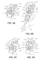
- Figs. 3A to 3D are cross-sectional views showing a substantial part of the intake valve driving mechanism, where Fig. 3A shows the mechanism when a valve lift is 0 in a large-lift control state, Fig. 3B shows when the valve lift is the maximum in the large-lift control state, Fig. 3C shows when the valve lift is 0 in a small-lift control state, and Fig. 3D shows the valve lift is the maximum in the small-lift control state.
- Fig. 4 is graphs showing a setting example of the intake valve driving mechanism of this embodiment.
- Fig. 5 is a flowchart showing a control example of an engine of this embodiment.
- Fig. 6 is a flowchart showing the control example of the engine of this embodiment, which is continued from Fig. 5 .
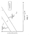
- Fig. 7 is a characteristic graph showing an example of an operating range determined in the flowchart of Fig. 5 .
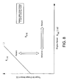
- Fig. 8 is a graph showing a control example of an intake valve closing timing in an earlier closing mode set in the flowchart of Fig. 5 .
- Fig. 9 is a graph showing the control example of the intake valve closing timing in the earlier closing mode set in the flowchart of Fig. 5 .
- Fig. 10 is a timing chart showing a control example in a retard transition mode in the flowchart of Fig. 5 .
- Figs. 11A and 11B are graphs showing an intake valve closing timing in a later closing mode set in the flowchart of Fig. 6 , where Fig. 11A shows the intake valve closing timing in an example where a throttle valve opening is changed when a target air charge amount varies at a given engine speed, and Fig. 11B shows the intake valve closing timing in an example where the throttle valve opening is maintained constant when a target air charge amount varies at a given engine speed.
- Figs. 12A and 12B are graphs showing a control example of the throttle valve opening in the later closing mode set in the flowchart of Fig. 6 , where Fig. 12A shows the throttle valve opening in the example of Fig. 11A , and Fig. 12B shows the throttle valve opening in the example of Fig. 11B .
- Fig. 13 is a timing chart showing a control example in an advance transition mode in the flowchart of Fig. 6 .
- Figs. 14A and 14B are graphs of the intake valve closing timing showing the control examples with which the flowcharts of Figs. 5 and 6 are performed, where Fig. 14A shows the intake valve closing timing in the example of Figs 11A and 12A , and Fig. 14B shows the intake valve closing timing in the example of Figs. 11B and 12B .
- Fig. 1 is a schematic configuration drawing of an internal combustion engine system according to an embodiment of the invention.
- the internal combustion engine system includes an engine 1, various actuators, various sensors, and an engine controlling unit 100 as a controller controlling the actuator(s) based on a signal from the sensor(s) which are associated with the engine 1.
- the engine 1 is preferably a spark-ignited internal combustion engine which has preferably four cylinders, including a first to a fourth four cylinder 11; however, the number of cylinders may be any number.
- the engine 1 is installed in a vehicle such as an automobile, and a crankshaft 14 thereof is coupled to drive wheels via a transmission to drive a vehicle.
- the engine 1 according to the embodiment has a geometric compression ratio of 13:1 or greater, and the geometric compression ratio is preferably 14:1 or greater and 16:1 or smaller. Such geometric compression ratios lead to increased compression ratios thereby, increasing the engine efficiency. Therefore, in the embodiment, the geometric compression ratio is set to 13:1 or greater to obtain high torque and sufficiently decrease fuel consumption while avoiding knocking by way of retarded ignition timing and the like.
- an upper limit of the geometric compression ratio is preferably set to 16:1 or smaller.
- the engine main body 1 includes a cylinder block 12 and a cylinder head 13 placed thereon, inside which a cylinder 11 is formed.
- a crankshaft 14 is rotatably supported in the cylinder block 12 by a journal, a bearing and the like. This crankshaft 14 is coupled to piston (disposed within the cylinders) via a connecting rod 16.
- a piston 15 is slidably inserted and fitted to each of the cylinder 11 to define a combustion chamber 17.
- the cylinder head 13 is formed with two intake ports 18 for every cylinder 11, only one of which is shown in Fig. 1 , and which intake ports communicate with the combustion chamber 17.
- the cylinder head 13 is formed with two exhaust ports 19 for every cylinder 11, which exhaust ports communicate with the combustion chamber 17.
- an intake valve 21 and an exhaust valve 22 are provided to block (close) the intake port 18 and the exhaust port 19 from the combustion chamber 17, respectively.
- the intake valve 21 is driven by an intake valve driving mechanism 30 as a valve operating device to reciprocate at a predetermined timing to open and close the intake port 18.
- the exhaust valve 22 is driven by an exhaust valve driving mechanism 40 to reciprocate at a predetermined timing to open and close the exhaust port 19.
- the intake valve driving mechanism 30 has preferably an intake camshaft 31, and the exhaust valve driving mechanism 40 has preferably an exhaust camshaft 41.
- the camshafts 31 and 41 are preferably coupled to the crankshaft 14 via a power transmission mechanism such as a known chain-sprocket mechanism.
- the power transmission mechanism is configured such that the camshafts 31 and 41 rotate one time while the crankshaft 14 rotates two times.
- a phase angle of the camshaft is preferably detected by a cam phase sensor 35, and a detected signal ⁇ VCT _ A thereof is preferably inputted to the engine controlling unit 100.
- a spark plug 51 is attached to the cylinder head 13 with a known configuration such as a thread.
- An ignition system 52 receives a control signal SA D from the engine controlling unit 100 to apply current to the spark plug 51 such that the spark plug 51 generates a spark at a desired ignition timing.
- Fuel injectors 53 are attached to one side of the cylinder head 13 (an intake side in the illustrated example) with a known configuration using, for example, a bracket.
- the fuel injector 53 is arranged such that a tip thereof is positioned below the intake port 18 in a vertical direction and midway between the two intake ports 18 (as described above) in a horizontal direction to face the inside of the combustion chamber 17.
- a fuel supply system 45 includes a high-pressure pump (not shown) for supplying the fuel injector 53 with pressure-raised fuel, a pipe and hose for feeding the fuel from the fuel tank to this high-pressure pump, and an electrical circuit for actuating the fuel injector 53.
- the electrical circuit receives the control signal FP D from the engine controlling unit 100 to actuate a solenoid of the fuel injector 53 to inject a target amount of fuel at a predetermined timing.
- the intake port 18 preferably communicates with a surge tank 55a by way of an intake pathway 55b in an intake manifold 55.
- Intake flow from an air cleaner, not shown, preferably passes through a throttle body 56 to be supplied to the surge tank 55a.
- the throttle body 56 has a throttle valve 57 arranged therein, which narrows the intake flow flowing to the surge tank 55a and adjusts the flow volume thereof.
- a throttle valve actuator 58 receives the control signal TVO D from the engine controlling unit 100 to adjust the opening of the throttle valve 57.
- the exhaust port 19 preferably communicates with a passage in the exhaust pipe by way of an exhaust pathway in an exhaust manifold 60, as is known.
- An exhaust passage downstream of the exhaust manifold 60 has an exhaust gas treatment system arranged therein having one or more catalytic converters, for example catalytic converter 61.
- the catalytic converter 61 may be a known three-way catalyst, a lean NOx catalyst, an oxidation catalyst and the like.
- Other exhaust gas treatment systems or devices may be used alternatively or additionally to catalytic converter 61, so long as they satisfy the purpose of exhaust gas treatment by a specific fuel control method.
- the intake manifold 55 (downstream of the throttle valve 57) and the exhaust manifold 60 are preferably coupled with each other via an exhaust gas recirculation (EGR) pipe 62 such that a part of the exhaust gas is recirculated to an intake system (hereinafter, also referred to as EGR). Since the pressure on the exhaust side is higher than that on the intake side, a part of the exhaust gas flows into the intake manifold 55 (referred to as EGR gas) to be mixed with new air inducted from intake manifold 55 to the combustion chamber 17.
- EGR pipe 62 is provided with an EGR valve 63 so as to adjust the flow volume of the EGR gas.
- An EGR valve actuator 64 receives the control signal EGR OPEN from the engine controlling unit 100 to adjust the opening of the EGR valve 63.
- the engine controlling unit 100 is a controller using a known microcomputer as a base and includes a central processing unit (CPU) for executing programs, a memory such as a RAM and a ROM for storing programs and data, and an input and output (I/O) bus for inputting and outputting electric signals.
- CPU central processing unit
- memory such as a RAM and a ROM for storing programs and data
- I/O input and output
- the engine controlling unit 100 accepts various inputs such as the intake air flow AF from an air flow sensor 71, the intake manifold pressure MAP from an intake pressure sensor 72, and the crank angle pulse signal from a crank angle sensor 73.
- the engine controlling unit 100 calculates the engine speed N ENG ; for example, based on the crank angle pulse signal. Further, the engine controlling unit 100 also accepts the oxygen concentration EGO of the exhaust gas from an oxygen concentration sensor 74. Additionally, the engine controlling unit accepts a gas-pedal opening signal ⁇ from a gas-pedal opening sensor 75 for detecting the amount of depressing the gas pedal.
- the engine controlling unit 100 accepts the vehicle speed signal VSP from a vehicle speed sensor 76 for detecting the rotation speed of an output shaft of the transmission.
- the engine controlling unit 100 calculates such a control parameter of the engine 1 as follows based on the input described above.
- the parameter includes a target throttle valve opening TVO, a fuel injection amount FP, an ignition timing SA, a valve phase angle ⁇ VCT , and an EGR amount (EGR valve opening) Q EGR .
- corresponding control signals are outputted as a throttle valve opening signal TVO D , a fuel injection pulse signal FP D , an ignition pulse signal SA D , a valve phase angle signal ⁇ VCT _ D , a valve lift signal ⁇ VVL _ D , and an EGR opening signal EGR OPEN to the throttle valve actuator 58, the fuel supply system 45, the ignition system 52, the intake valve driving mechanism 30, the EGR actuator 64 and the like.
- FIG. 2 is a perspective view showing a specific configuration of the intake valve driving mechanism 30 according to the embodiment of Fig. 1
- Figs. 3A to 3D which are cross-sectional views showing a substantial part of the intake valve driving mechanism 30 including example components and elements.
- Fig. 3A shows a time when a valve lift is a value of 0 in a large lift controlling state
- Fig. 3B shows a time when the valve lift is the maximum in the large lift controlling state
- Fig. 3C shows a time when the valve lift is a value of 0 in a small lift controlling state
- Fig. 3D shows a time when the valve lift is the maximum in the small lift controlling state.
- the intake valve driving mechanism 30 includes preferably a variable cam timing mechanism (VCT mechanism) 32, which preferably is driven and coupled by a chain drive mechanism to the crankshaft 14.
- VCT mechanism variable cam timing mechanism
- the chain drive mechanism includes in addition to a driven sprocket 104, a drive sprocket (not shown) of the crankshaft 14 and a chain wound around both sprockets.
- the VCT mechanism 32 includes preferably a case fixed to the driven sprocket 104 so as to rotate integrally, and preferably a rotor accommodated in the case and fixed to an inner shaft 105 so as to rotate integrally. Between the case and the rotor, a plurality of hydrostatic chambers are formed around a center axis X (shown in Figs. 3A to 3D ) in an aligned state (circumferentially). Then, a liquid (for example, engine oil) pressurized by the pump is selectively supplied to each of the hydrostatic chambers to form a pressure difference between the hydrostatic chambers facing each other.
- a liquid for example, engine oil
- the engine controlling unit 100 as a VCT control unit outputs a control signal ⁇ VCT _ D to a magnetic valve 32a of the VCT mechanism 32, which the magnetic valve 32a receives to duty-control a hydraulic pressure so as to adjust the flow rate, pressure and the like of the liquid supplied to the hydrostatic chamber.
- This makes it possible to change the actual phase difference between the sprocket 104 and the inner shaft 105 to achieve a target rotation phase of the inner shaft 105 as is known.
- the VCT control unit may be configured as another configuration unit besides that of the engine controlling unit 100.
- the inner shaft 105 has cams 106 of a disk shape provided integrally thereto corresponding to the respective cylinders (of which cylinder 11 is an example) as shown in Figs. 3A to 3D .
- Cams 106 protrude eccentrically from the center of the axis of the inner shaft 105, and rotate with a phase defined by the VCT mechanism 32.
- Peripheries of eccentric cams 106 are fitted rotatably with inner peripheries of ring arms 107.
- the ring arms 107 revolve around the same center axis X and at the same time turns around the center of the eccentric cams 106.
- the inner shaft 105 is preferably provided with a rocker connecter 110 for each of the respective cylinders of engine 1.
- Each rocker connecter 110 has a cylinder shape and inserted by the inner shaft 105 to be supported concentrically; in other words, rotatably supported around the center axis X.
- the peripheries of the rocker connecters 110 are made to be a bearing journal and rotatably supported by a bearing cap (not shown) provided to the cylinder head 13.
- First rocker cams 111 and second rocker cams 112 are coupled to the rocker connecter 110. Configurations of both are preferably the same, thus Figs. 3A to 3D show one of the rocker cams 111, with a cam face 111 a and a base face 111 b of a circumferential shape (see Fig. 3D ), which are slidable on the upper surface of a tappet 115.
- the rocker cam 111 does not continuously rotate, and presses the tappet 115 to open the valve similarly to the cam of a general intake valve driving mechanism except for oscillation.
- the tappet 115 is preferably supported by a valve spring 116.
- the valve spring 116 is preferably supported between holders 117 and 118 as is known.
- This control shaft 120 is rotatably supported by a bearing (not shown), and at an approximately central portion of the shaft in a longitudinal direction thereof provided integrally is a worm gear 121 of a coaxial shape protruding from the periphery.
- the worm gear 121 engages with a worm 122.
- This worm 122 is fixed to the output shaft, for example, a stepping motor 123 which is an actuator of a variable valve lift mechanism (VVL). Therefore, the stepping motor 123, having received the control signal (valve lift signal) ⁇ VVL_D from the engine controlling unit 100. operates the control shaft 120 so as to turn to a target position.
- the control shaft 120 turned in this way preferably has control arms 131 attached for the respective cylinders 11 of engine 1, and these control arms 131 are turned integrally by the turning of the control shaft 120.
- control arm 131 turned in this way is coupled to the ring arm 107 via a control link 132. That is, an end of the control link 132 is coupled rotatably to the tip of the control arm 131 with a control pivot 133, and the other end of the control link 132 is preferably coupled rotatably to the ring arm 107 with a common pivot 134.
- the common pivot 134 couples the other end of the control link 132 to the ring arm 107 as described above, and penetrates through this ring arm 107 to rotatably couple the ring arm to the end of the a rocker link 135. Then, the other end of this rocker link 135 is rotatably coupled to rocker cam 111 with a rocker pivot 136, which makes it possible to transmit the rotation of the ring arm 107 to the rocker cam 111.
- a position of the common pivot 134 coupling the ring arm 107 and the control link 132 is defined by the position relationship of three of the positions of the control pivot 133, and the common center positions of the eccentric cams 106 and the ring arm 107.
- the common pivot 134 reciprocates approximately vertically in response to only the rotation about the common centers of the eccentric cams 106 and the ring arms 107.
- Such a reciprocation of the common pivot 134 is transmitted to the first rocker cam 111 by the rocker link 135, and swings the first rocker cam 111 around the center axis X together with the rocker cam 112 coupled to the cam 111 by the rocker connecter 110.
- the rocker cam 111 swung in this way, as shown in Figs. 3B and 3C , presses down the tappet 115 against a spring force of the valve spring 116 while the cam face 111 a is contacting with the upper surface of the tappet 115, and the tappet 115 presses down the intake valve 21 to open the intake port 18.
- the tappet 115 is not pressed down. This is because the radius of the base surface 111 b of the rocker cam 111 centering on the center axis X is preferably set to be equal to the distance between the center axis X and the upper surface of the tappet 115 or less.
- the position change of the control pivot 133 generates the position variation among the three; thus, the common pivot 134 traces a locus different from the above, to reciprocate.
- an operation of a motor 123 rotates the control shaft 120 and the control arm 131 to change the position of the control pivot 133, which makes it possible to change the swing range of the rocker cams 111 and 112.
- the swing range of the rocker cam 111 may be such that the base surface 111 b relatively is more likely to contact with the upper surface of the tappet 115.
- Fig. 4 is a graph showing a setting example of the intake valve driving mechanism 30 according to the embodiment.
- a valve lift ⁇ VVL is controlled in a range; for example, from ⁇ VVL _ min to ⁇ VVL_max by the intake valve driving mechanism 30 described above and the relating constituent components as a target amount CE of air to be inducted into each cylinder 11 increases, and the intake valve closing timing is retarded in a range from ⁇ VCT _ min to ⁇ VCT _ max as the valve lift ⁇ VVL increases.
- the opening operation timing and the closing operation timing of the intake valve 21 may be any combination as needed, for example, a lost motion in which the valve lift is 0 (zero) may be possible.
- the opening timing of the intake valve 21 starts opening the valve immediately before the exhaust top dead center (for example, crank angle of 20°CA before the top dead center) in the most operating range and changes the closing timing in response to the target air charge amount.
- the closing timing of the intake valve 21 may be set to occur during, a first range IVC 1st , which is advanced from the intake valve closing timing with which a target air charge amount CE is maximized at the engine speed N ENG , and a second range IVC 2nd , which is retarded from the intake valve closing timing with which a target air charge amount CE is maximized at the engine speed N ENG and separated from the first range IVC 1st .
- an earlier closing mode M EIVC for driving such that the intake valve 21 closes in the first range IVC 1st
- a later closing mode M LIVC for driving such that the intake valve 21 closes in the second range IVC 2nd
- an advance transition mode M TR-A for switching the driving mode from the later closing mode M LIVC to the earlier closing mode M EIVC
- a retard transition mode M TR-R for switching the driving mode from the earlier closing mode M EIVC to the later closing mode M LIVC .
- both first and second ranges are set to include the intake valve closing timing with which the target air charge amount CE is maximized at the engine speed N ENG , and is not necessarily to be set using an intake bottom dead center as a reference, as described below in detail (see Figs. 14A and 14B , described later).
- the earlier closing mode M EIVC is a mode which is selected when an engine operation condition is a low-load condition and in which the valve lift ⁇ VVL of the intake valve 21 is made smaller and the intake valve closing timing is advanced from the intake bottom dead center; for example, corresponding to the valve lift ⁇ VVL .
- the later closing mode M LIVC is a mode which is selected when the engine operation condition is a high-load condition and in which the valve lift ⁇ VVL of the intake valve 21 is made greater and the intake valve closing timing is retarded beyond the intake bottom dead center corresponding to a greater valve lift ⁇ VVL .
- the second range IVC 2nd (in which the later closing mode M LIVC is set) is retarded and separated from the first range IVC 1st in which the earlier closing mode M EIVC is set. Therefore, an intermediate range IVC IM in which the intake valve 21 is not closed is set between the valve closing timing ranges IVC 1st and IVC 2nd .
- the closing timing of the intake valve 21 can be either advanced or retarded from a timing with which amount of air inducted into the cylinder is maximized at a given engine speed. If the intake valve closing timing is advanced from that timing at the given engine speed, the swing of the rocker cam 111 becomes smaller and resistance of the valve spring 116 also becomes smaller, which improves engine operating efficiency and is preferable in the low-load condition, as is clear from Figs. 3A and 3B . However, the closing timing of the intake valve 21 for obtaining a predetermined cylinder air charge amount is retarded as the engine speed increases as a result of an increase of the engine torque.
- a limiting the target intake valve closing timing towards the advanced side is less needed as the engine speed is greater because higher engine speed can enhance fluidity of air-fuel mixture in a cylinder and the possibility of abnormal combustion is decreased. Accordingly, the closing timing of the intake valve 21 is necessary to be retarded at higher rate as the engine speed increases. However, it is difficult to retard the closing timing of the intake valve 21 at higher rate toward a target intake valve closing timing due to the delay of response of the intake valve driving mechanism 30. This may cause the actual intake valve closing timing to occur earlier than the target intake valve closing timing, which may result in decreasing the cylinder air charge amount.
- the intake valve closing timing IVC is retarded from a timing with which the amount of air inducted into the cylinder is maximized at a given engine speed, the air is inducted into the cylinder 11 until the piston 15 reaches the bottom dead center. Then, the air in the cylinder is returned to the intake passage during an upward motion of the example piston 15 after the bottom dead center to reduce the effective compression ratio.
- the first range IVC 1st and the second range IVC 2nd are set to utilize a greater expansion ratio of a high compression ratio engine while taking measures to regulate abnormal combustion such as knocking in the intermediate range IVC 1M with higher possibility of the abnormal combustion, thereby improving the output and reduce the fuel consumption in a continuous, broader operating range.
- Figs. 5 and 6 are the flowcharts showing example control methods for controlling the engine 1 according to the embodiment of the invention.
- the engine controlling unit 100 executes initialization of various settings (step S1). In this initialization, the engine controlling unit 100 sets a current operation mode M to the earlier closing mode M EIVC .
- the engine controlling unit 100 reads or calculates a gas-pedal opening signal ⁇ from the gas-pedal opening sensor 75, the engine speed N ENG based on a crank angle pulse signal, and the vehicle speed signal VSP from the vehicle speed sensor 76 to calculate a target torque TQ based on the information (step S2).
- the engine controlling unit 100 calculates the fuel injection amount FP (or air-fuel ratio), the target air charge amount CE, the EGR amount Q EGR and the ignition timing SA based on the target torque TQ and the engine speed N ENG (step S3).
- the engine controlling unit 100 reads data of a control map M1 stored in the memory in advance, and determines a current operating range R fitted to values of the target air charge amount CE and the engine speed N ENG based on this control map M1 (step S4). As a result, the engine controlling unit 100 determines the operating range as shown in Fig. 7 .
- Fig. 7 is a characteristic graph showing an example of the operating range determined in the flowchart of Fig. 5 .
- characteristics L1 and L2 (an example of the predetermined air charge amount) proportional to the engine speed N ENG are set, and there are set such that the later closing mode M LIVC is selected in the operating range R LIVC which is on the high-load side of the high-load characteristic L1 or more, and the earlier closing mode M EIVC is selected in the operating range R EIVC which is on the low-load side of the low-load characteristic L2 or less.
- a transient range R TR between the characteristic L1 and the characteristic L2 is a range where hysteresis is provided and used for switching the operation mode.
- the operation mode is kept in the earlier closing mode M EIVC until the engine speed and target air charge amount exceeds the characteristic L1, even if the target air charge amount leaves the operating range R EIVC .
- the operation mode is kept in the later closing mode M LIVC until the engine speed and target air charge amount exceeds the characteristic L2, even if the target air charge amount leaves the operating range R LIVC .
- the later closing mode M LIVC and the earlier closing mode M EIVC are selected with the range partitioned by a single characteristic without this hysterisis.
- the engine controlling unit 100 determines whether or not the current operation mode M is the earlier closing mode M EIVC (step S5). If the operation mode M is the earlier closing mode M EIVC , the engine controlling unit 100 further determines the operating range R based on current target air charge amount CE and engine speed N ENG , and determines whether the current operating range R is other than the later closing operating range R LIVC ; that is, whether the valve closing timing range IVC of the intake valve 21 is other than the second range IVC 2nd (step S6). If the current operating range R is other than the later closing operating range R LIVC , the engine controlling unit 100 sets the operation mode M to be the earlier closing mode M EIVC (step S7).
- the engine controlling unit 100 calculates the valve lift ⁇ VVL of the intake valve 21, a valve opening period ⁇ VCT of the intake valve 21 and the throttle valve opening TVO based on the target air charge amount CE and the engine speed N ENG at this earlier closing mode M EIVC (step S8).
- the engine controlling unit 100 outputs the control signal FP D , EGR OPEN , SA D , ⁇ VVL_D , ⁇ VCT _ D and TVO D corresponding to the calculated valve lift ⁇ VVL , valve opening period ⁇ VCT and throttle valve opening TVO, as well as the fuel injection amount FP, EGR amount Q EGR and ignition timing SA calculated in step S3 to control the actuators of the intake valve driving mechanism 30 and the throttle valve 57. Thereafter, the process moves to step S2 to repeat the above described control.
- Fig. 8 is a graph showing a control example of the intake valve closing timing in the earlier closing mode M EIVC set in the flowchart of Fig. 5 .
- Fig. 9 is a graph showing a control example of the throttle valve opening in the earlier closing mode M EIVC set in the flowchart of Fig. 5 .
- a characteristic L3 parallel to the characteristic L1 and proportional to the engine speed N ENG is set on the low-load side.
- the characteristic L3 may be on the low-load side of the characteristic L2 (as shown in Fig. 8 ), or may be the equal to or greater than the characteristic L2 as long as the characteristic L3 is smaller than the characteristic L1.
- the throttle valve opening TVO is set to be fully opened, and the target air charge amount CE is substantially controlled by the closing timing of the intake valve 21. Therefore, enough air charge amount CE is obtained, making it possible to control so as not to generate pumping loss.
- control is performed such that the throttle valve opening TVO decreases in a range from the characteristic L3 to the characteristic L1, as the target load increases or the engine speed N ENG decreases. For this reason, as the operation condition changes from a middle high-speed, low middle-load operating range to the low-speed, high-load operating range where the operation mode M needs to be set to the later closing mode M LIVC , the pressure in the intake passage including the intake port 18 downstream of the throttle valve 57 is reduced.
- step S6 in a case that the current operating range R is the later closing range R LIVC (NO, in step S6), the engine controlling unit 100 sets the operation mode M to the retard transition mode M TR-R (step S10). Then, the engine controlling unit 100 sets a predetermined count time period C TR-R as a count value C TR (step S11). Based on the target air charge amount CE and the engine speed N ENG in the retard transition mode M TR-R , the valve lift ⁇ VVL of the intake valve 21, the valve timing ⁇ VCT of the intake valve 21, the EGR amount Q EGR and the throttle valve opening TVO are calculated (step S12).
- the reason for providing the predetermined count time period C TR-R is in order for the charge amount CE to be provisionally reduced to prevent abnormal combustion (such as pre-ignition) until the shift of the closing timing of the intake valve 21 from the first range IVC 1st to the second range IVC 2nd .
- step S12 the process moves to step S9 to output the control signal FP D , EGR OPEN , SA D , ⁇ VVL _ D , ⁇ VCT _ D and TVO D corresponding to the valve lift ⁇ VVL , valve timing ⁇ VCT , EGR amount Q EGR , throttle valve opening TVO calculated in the retard transition mode M TR-R , as well as the fuel injection amount FP and ignition timing SA calculated in step S3, thereby controlling the actuators of the intake valve driving mechanism 30 and the throttle valve 57.
- step S2 the process moves to step S2 to repeat the above described control.
- Fig. 10 is a timing chart showing a control example in the retard transition mode M TR-R according to the flowchart in Fig. 5 .
- the count value C TR is decremented from a start timing t0 thereof (see step S27 in Fig.6 ), and the control ends at a timing t2.
- the intake valve driving mechanism 30 starts retarding in order to shift the closing timing of the intake valve 21 to the second range IVC 2nd from the timing t0 when the counting starts.
- the throttle valve opening TVO reduces in proportion as a closing timing of the intake valve 21 is retarded, thereby reducing the intake passage pressure.
- the opening (EGR amount) Q EGR of the EGR valve 63 increases in proportion as the closing timing of the intake valve 21 is retarded. This causes the outer EGR gas to be inducted into the cylinder.
- the outer EGR gas has a lower temperature than an inner EGR gas, i.e., the gas remaining in the cylinder, allowing abnormal combustion to be prevented more surely.
- the engine controlling unit 100 further determines whether or not the operation mode M is the later closing mode M LIVC (step S20). If the operation mode M is the later closing mode M LIVC , the engine controlling unit 100 further determines the operating range R based on the current target air charge amount CE and the engine speed N ENG , and determines whether the current operating range R is other than the earlier closing operating range R EIVC ; that is, whether the valve closing timing range IVC of the intake valve 21 is other than the first range IVC 1st (step S21). If the current operating range R is other than the earlier closing operating range R EIVC , the engine controlling unit 100 sets the operation mode M to the later closing mode M LIVC (step S22).
- the engine controlling unit 100 calculates the valve lift ⁇ VVL of the intake valve 21, the valve timing ⁇ VCT of the intake valve 21 and the throttle valve opening TVO based on the target air charge amount CE and the engine speed N ENG in this later closing mode M LIVC , (step S23).
- the engine controlling unit outputs the control signal FP D , EGR OPEN , SA D , ⁇ VVL_D , ⁇ VCT_D and TVO D corresponding to the calculated valve lift ⁇ VVL , valve opening period ⁇ VCT and throttle valve opening TVO, as well as the fuel injection amount FP, EGR amount Q EGR and ignition timing SA calculated in step S3, thereby controlling the actuators of the intake valve driving mechanism 30 and the throttle valve 57.
- the process moves to step S2 to repeat the above described control.
- Figs. 11A and 11B are graphs showing a control example of the intake valve closing timing in the later closing mode M LIVC set in the flowchart of Fig. 6 .
- Figs. 12A and 12B are graphs showing a control example of the throttle valve opening in the later closing mode M LIVC set in the flowchart of Fig. 6 .
- Figs. 11A and 12A illustrate a case of controlling the throttle valve opening in parallel depending on the target air charge amount CE
- Fig. 11B and 12B illustrate cases when the throttle is controlled, maintaining the throttle valve opening at a constant value.
- the closing timing of the intake valve 21 is made constant regardless of the increase and decrease of the target air charge amount CE to control the pressure in the intake passage including the intake port 18 downstream of the throttle valve 57, thereby changing the cylinder air charge amount.
- the intake valve closing timing comes close to the valve closing timing with which the maximum cylinder air charge at a given time would be obtained as it advances in the second valve closing timing IVC 2nd , to control the cylinder air charge amount.
- the throttle valve opening TVO is maintained substantially constant at a relatively larger value to keep the pressure in the intake passage high, thereby maintaining a state of low pumping loss.
- the engine controlling unit 100 sets the operation mode M to the advance transition mode M TR-A (step S24).
- the M TR-A mode may include the engine controlling unit 100 setting a predetermined count time period C TR-A as to the count value C TR (step S25), and calculating the valve lift ⁇ VVL of the intake valve 21, the valve opening period ⁇ VCT of the intake valve 21, the EGR amount Q EGR and the throttle valve opening TVO based on the target air charge amount CE and engine speed N ENG .
- step S26 After executing step S26, the process moves to step S9, and the engine controlling unit outputs the control signal FP D , EGR OPEN , SA D , ⁇ VVL_D , ⁇ VCT _ D and TVO D corresponding to the valve lift ⁇ VVL , valve opening period ⁇ VCT . Further the engine controlling unit may output EGR amount Q EGR , and throttle valve opening TVO calculated in the advance transition mode M TR-A , as well as the fuel injection amount FP and ignition timing SA calculated in step S3. By outputting such signals described above, the engine controlling unit thereby enables the control of the actuators of the intake valve driving mechanism 30 and the throttle valve 57. Thereafter, the process moves to step S2 to repeat the above described control.
- Fig. 13 is a timing chart showing a control example in the advance transition mode M TR-A in the flowchart of Fig. 6 .
- the intake valve driving mechanism 30 starts advancing in order to shift the closing timing of the intake valve 21 to the first range IVC 1st from the timing t0 when the counting starts.
- the throttle valve opening TVO reduces as the closing timing of the intake valve 21 is advanced, thereby reducing the intake passage pressure. This makes it possible to prevent abnormal combustion with reduction of the intake passage pressure even if the intake valve 21 of the cylinder 11 is brought into the intermediate range IVC IM having the possibility of abnormal combustion such as pre-ignition.
- the opening of the EGR valve 63 increases in proportion as the closing timing of the intake valve 21 is advanced. This causes the relatively lower temperature outer EGR gas to be inducted into the cylinder, further suppressing abnormal combustion.
- the engine controlling unit 100 decrements the count value C TR (step S27), and determines whether or not the operation mode M is the advance transition mode M TR-A (step S28).
- step S29 the engine controlling unit 100 determines whether or not the count value C TR is larger than 0 (step S29). If the count value CTR is larger than 0, the engine controlling unit 100 performs control of step S26 and subsequent steps. This allows the operation control to continue in the advance transition mode M TR-A .
- step S29 If the count value CTR is less than or equal to 0 in step S29, the process moves to step S7 and subsequent steps because the operation mode switching of the intake valve 21 by the intake valve driving mechanism 30 has already completed.
- the operation mode M is switched to the earlier closing mode M EIVC , and the above described operation control in the earlier closing mode is repeated.
- step S30 the engine controlling unit 100 determines whether or not the count value C TR is larger than 0 (step S30). If the count value C TR is larger than 0, the engine controlling unit 100 executes control of step S12 and subsequent steps. This allows the operation control to continue in the retard transition mode M TR-R . On the other hand, if the count value C TR is found to be equal to or less than 0 in step S30, the process moves to step S22 and subsequent steps because the operation mode switching of the intake valve 21 by the intake valve driving mechanism 30 has already completed. The operation mode M is switched to the later closing mode M LIVC , and then the above described operation control in the earlier closing mode is repeated.
- Figs. 14A and 14B are graphs of the intake valve closing timing showing control examples resulting from methods carried out in the flowcharts of Figs. 5 and 6 .
- Fig. 14A represents a case where the throttle valve opening is changed while the intake valve closing timing is maintained to be constant in the later closing mode M LIVC
- Fig. 14B represents a case where the throttle valve opening is maintained constant while changing the control of the intake valve closing timing in the later closing mode M LIVC .
- the target air charge amount CE may be controlled with the closing timing of the intake valve 21 being fixed to a most advanced timing, thereby minimizing the shift amount of the intake valve closing timing (turn angle of the control shaft 120 in Figs. 3A to 3D ) in switching from the earlier closing mode M EIVC to the later closing mode M LIVC , resulting to allowing the time required to switch from the earlier closing mode MEIVC to be as short as possible.
- the intake valve closing timing is retarded as the engine speed N ENG increases, the higher the engine speed N ENG is, the smaller the intermediate range IVC IM between the first range IVC 1st and the second range IVC 2nd is.
- the intake valve 21 closes almost in the first range IVC ,P," " at certain engine speeds (2500 min -1 (rpm), for example) or more, make any shift of the operation mode M unnecessary.
- the embodiment preferably provides an engine system including: the engine 1 having the cylinder 11 accommodating the piston 15 which reciprocates therein and defining the combustion chamber 17, the intake port 18 through which air is inducted into the combustion chamber 17, and the intake valve 21 capable of blocking the intake port 18 from the combustion chamber 17; the intake valve driving mechanism 30 as a variable valve operating system which is configured to substantially maintain the opening timing of the intake valve, and retards the closing timing of the intake valve 21 as the target amount CE of air to be inducted into each cylinder 11 increases; and the engine controlling unit 100 as the controller.
- step S20 to S23 in Fig. 6 , and step S9 in Fig.5 included is a step where the engine controlling unit 100 closes the intake valve 21 in the second range IVC 2nd which is set to be retarded from the intake valve closing timing with which the target air charge amount CE is maximized at the given engine speed N ENG in each cylinder cycle and separated from the first range, when the target air charge amount CE is equal to or more than a predetermined air charge amount (steps S20 to S23 in Fig. 6 , and step S9 in Fig.5 ).
- the intake valve 21 is preferably closed in the first range IVC 1st (before the bottom dead center, for example) when the target air charge amount CE is smaller than a predetermined air charge amount, whereas the intake valve 21 is closed in the second range IVC 2nd (after the bottom dead center, for example) when the target air charge amount CE is equal to or more than a predetermined air charge amount.
- the engine 1 is operated with a small valve opening amount suitable for the required air charge amount CE by the earlier closing operation in the operating range where the target air charge amount CE is relatively small, reducing mechanical loss due to excessive valve operation, and the required air charge amount CE is fully secured and abnormal combustion such as pre-ignition can be inhibited by the later closing operation in the operating range in which a target air charge amount CE is high.
- the engine output increases in an engine high-load condition in which the target air charge amount CE is high with a high possibility of increasing the engine speed N ENG thereafter.
- the higher the engine speed the more retarded the intake valve closing timing is for obtaining a constant air charge amount CE. Accordingly, by setting the valve closing timing of the intake valve 21 in the second range IVC 2nd in advance when the engine speed is in a low operation range, a frequency of the intake valve closing timing being within the intermediate range IVC IM located between the first range IVC 1st and the second range IVC 2nd during the engine speed increasing under a high-load condition is minimized. Minimizing the frequency of the intake valve closing being within the intermediate range IVC IM minimizes the extent of decreasing the intake passage pressure to minimize pumping loss. Therefore, the expansion ratio is increased while preventing an occurrence of problems accompanied by a high compression ratio to allow engine operation efficiency to be improved.
- the first range IVC 1st is before the intake bottom dead center of each cylinder cycle
- the second range IVC 2nd is after the intake bottom dead center of each cylinder cycle in a low speed operating range of the engine 1. Therefore, in this embodiment, particularly in the low speed operating range having the pre-ignition problem, the expansion ratio is increased in a setting range where abnormal combustion such as pre-ignition is reliably inhibited to allow engine operation efficiency to be improved.
- the intake valve closing timing on this occasion is set on a relatively advanced side in the second range IVC 2nd , that is, on a side close to the first range IVC 1st .
- the intake passage pressure is decreased at that time, thereby enabling the prevention of abnormal combustion such as pre-ignition.
- the target air charge amount CE when the target air charge amount CE is equal to, or more than a predetermined air charge amount (that is, in the later closing mode M LIVC where the intake valve 21 is subjected to a closing-valve control in the second range IVC 2nd ), as the target air charge amount CE increases, the closing timing of the intake valve 21 of each cylinder cycle is advanced (controls of Figs. 11B , 12B , 13B and 14B ). Therefore, in this embodiment, the target air charge amount CE can be obtained over a broad operating range without pumping loss.
- a predetermined air charge amount that is, in the later closing mode M LIVC where the intake valve 21 is subjected to a closing-valve control in the second range IVC 2nd
- this embodiment preferably provides an internal combustion engine system including: the engine 1 having the cylinder 11 accommodating the piston 15 which reciprocates therein and defining the combustion chamber 17, the intake passage (such as the intake manifold 55 and the intake port 18) through which air is inducted into the combustion chamber 17, and the intake valve 21 capable of blocking the intake port from the combustion chamber 17; the intake valve driving mechanism 30 as the variable valve operating system changes the intake valve 21 periodically; the throttle valve 57 which is provided to the intake passage and can narrow the airflow flown into the cylinder 11; and the engine controlling unit 100 as the controller for controlling the intake valve driving mechanism 30 and the throttle valve 57.
- the engine controlling unit 100 achieves a step where when the intake valve 21 closes on the advanced side from the intake valve closing timing IVC with which the air charge amount is maximized at the given engine speed N ENG in each cylinder cycle In such an example, the intake valve closing timing IVC is retarded as the target amount CE of air to be inducted into each cylinder 11 increases (control of Fig. 8 ).
- the embodiment further achieves a step where the pressure in the intake passage is decreased as the intake valve closing timing IVC is retarded (control of Fig. 9 ).
- the target air charge amount CE can be obtained with the intake passage pressure being maintained high until the cylinder air charge amount reaches a point which is too high, and thus having a possibility of abnormal combustion occurrence.
- pumping loss is reduced to improve the engine operation efficiency when the engine operation condition is a low-load condition where the engine stays for relative long periods.
- the intake valve closing timing IVC may be retarded to come close to a timing with which the cylinder air charge amount is maximized in advance.
- the frequency of the closing operation of the intake valve 21 in the operating range R TR having a possibility of abnormal combustion can be minimized, and an appropriate cylinder air charge amount is achieved while decreasing a possibility of abnormal combustion associated with a high compression ratio even at a transient change.
- the intake valve closing timing IVC may come close to a timing with which the cylinder air charge amount is maximized.
- the frequency of the closing operation of the intake valve 21 in the operating range R TR having a possibility of abnormal combustion may be minimized, thereby preventing the problem accompanied by a high compression ratio from occurring and increasing the expansion ratio to improve engine operation efficiency.
- this embodiment also provides a control method including a step where the intake valve 21 closes later in each cylinder cycle as the target amount CE of air to be inducted into the cylinder 11 during each cylinder cycle increases. Further the control method includes a step where the pressure in the intake passage is decreased as the valve closing timing is retarded when the intake valve closing timing IVC is before a first predetermined timing in each cylinder cycle, and the pressure in the intake passage is increased as the valve closing timing is retarded when the intake valve closing timing IVC is later than the first predetermined timing in each cylinder cycle.
- the target air charge amount CE can be obtained with the intake passage pressure being maintained high until the cylinder air charge amount reaches to a point which is too high having a possibility of abnormal combustion occurrence by selecting the first predetermined timing; for example, the intake valve closing timing IVC with which the cylinder air charge amount is maximized at the given engine speed N ENG .
- the intake valve closing timing IVC with which the cylinder air charge amount is maximized at the given engine speed N ENG .
- the second range IVC 2nd is employed as the intake valve closing timing which is retarded and corresponds to an acceptable air amount at a time after the engine speed increases and when the possibility of abnormal combustion occurrence is decreased by decrease of the intake valve pressure.
- the intake valve closing timing IVC can come close to a timing with which the cylinder air charge amount is maximized when changing from the operating range R EIVC where the earlier closing operation is performed to the operating range R LIVC where the later closing operation is performed, resulting in that a frequency of the intake valve 21 performing the closing operation can be minimized in the operating range R TR having a possibility of abnormal combustion, thereby preventing a problem accompanied by a high compression ratio from occurring and increasing the expansion ratio to improve engine operation efficiency.
- the embodiment provides a method including a step where the intake valve 21 closes later in the cylinder cycle as the target amount CE of air to be inducted into the cylinder 11 in each cylinder cycle in a case of closing on the advanced side from the intake valve closing timing IVC with which the cylinder air charge amount is maximized at the engine speed N ENG , and a step where the opening the throttle valve 57 is decreased as the intake valve closing timing IVC is retarded. Therefore, in this embodiment, the target air charge amount CE can be obtained with the opening of the throttle valve 57 being kept high and the intake passage pressure being maintained high until the cylinder air charge amount reaches to a point which is too high having a possibility of abnormal combustion occurrence.
- the decreased throttle valve opening is increased as the intake valve closing timing IVC is retarded. Therefore, in this embodiment, when the intake valve closing timing IVC is retarded until a possibility of abnormal combustion occurrence decreases, the opening of the throttle valve 57 is increased to increase the intake passage pressure, and thereby the intake pump loss can be reduced in the operating range of the high cylinder air charge amount.
- the EGR pipe 62 as an exhaust gas recirculation passage which recirculates the exhaust gas from the exhaust passage of the engine 1 to the intake passage, and included is a step where the amount of the EGR gas (EGR valve opening) passing the EGR pipe 62 is increased as the opening of the throttle valve 57 decreases. Therefore, in this embodiment, as the operating condition comes close to the operating range R TR where abnormal combustion is concerned, pre-ignition and the like are restricted by the outer EGR gas recycling from the EGR pipe 62 that has a lower temperature than the inner EGR gas (a gas remaining in the cylinder 11). Thus, engine operating efficiency is improved while avoiding abnormal combustion and decreasing pump loss over a broad operation range.
- the geometric compression ratio of the engine 1 is equal to 13 or more in this embodiment. Therefore, in this embodiment, the intake valve closing timing IVC is set before or after the intake valve closing timing IVC due to the high geometric compression ratio to allow the increase of the expansion ratio and further improvement of engine operation efficiency.
- the intake valve closing timing IVC may be retarded to come close to the timing IVC with which the cylinder air charge amount is maximized in advance.
- the expansion ratio is increased to improve engine operation efficiency while suppressing the possibility of abnormal combustion occurrence accompanied by a high compression ratio.
Landscapes
- Engineering & Computer Science (AREA)
- Chemical & Material Sciences (AREA)
- Combustion & Propulsion (AREA)
- Mechanical Engineering (AREA)
- General Engineering & Computer Science (AREA)
- Output Control And Ontrol Of Special Type Engine (AREA)
- Electrical Control Of Air Or Fuel Supplied To Internal-Combustion Engine (AREA)
Applications Claiming Priority (2)
| Application Number | Priority Date | Filing Date | Title |
|---|---|---|---|
| JP2008047333A JP5012565B2 (ja) | 2008-02-28 | 2008-02-28 | 内燃機関の制御方法および内燃機関システム |
| JP2008047332A JP5029423B2 (ja) | 2008-02-28 | 2008-02-28 | 内燃機関の制御方法 |
Publications (2)
| Publication Number | Publication Date |
|---|---|
| EP2096281A1 true EP2096281A1 (de) | 2009-09-02 |
| EP2096281B1 EP2096281B1 (de) | 2011-04-13 |
Family
ID=40566352
Family Applications (1)
| Application Number | Title | Priority Date | Filing Date |
|---|---|---|---|
| EP09002673A Ceased EP2096281B1 (de) | 2008-02-28 | 2009-02-25 | Verbrennungsmotorsteuerungsverfahren, Verbrennungsmotorsystem und entsprechendes Computerprogrammprodukt |
Country Status (3)
| Country | Link |
|---|---|
| US (1) | US8155862B2 (de) |
| EP (1) | EP2096281B1 (de) |
| DE (1) | DE602009001020D1 (de) |
Cited By (2)
| Publication number | Priority date | Publication date | Assignee | Title |
|---|---|---|---|---|
| WO2015092451A1 (en) * | 2013-12-20 | 2015-06-25 | Pakai Tibor | Device and procedure for increasing the efficiency of internal combustion engines |
| CN115045763A (zh) * | 2021-03-08 | 2022-09-13 | 马自达汽车株式会社 | 发动机 |
Families Citing this family (19)
| Publication number | Priority date | Publication date | Assignee | Title |
|---|---|---|---|---|
| JP4442659B2 (ja) * | 2007-08-09 | 2010-03-31 | トヨタ自動車株式会社 | 内燃機関の排気浄化装置 |
| JP5104948B2 (ja) * | 2008-06-30 | 2012-12-19 | 日産自動車株式会社 | 可変動弁機構付き内燃機関の制御装置 |
| JP4841638B2 (ja) * | 2009-02-12 | 2011-12-21 | 本田技研工業株式会社 | 内燃機関の点火時期制御装置 |
| JP5126410B2 (ja) * | 2009-02-20 | 2013-01-23 | トヨタ自動車株式会社 | 火花点火式内燃機関 |
| JP4862927B2 (ja) * | 2009-08-20 | 2012-01-25 | マツダ株式会社 | 火花点火式内燃機関の制御システム |
| US8851050B2 (en) * | 2010-03-31 | 2014-10-07 | Mazda Motor Corporation | Spark-ignition engine control method and system |
| KR101209742B1 (ko) * | 2010-11-04 | 2012-12-07 | 기아자동차주식회사 | 연속 가변 밸브 리프트(cvvl)기구 탑재 엔진간 밸브리프트 편차 보상방법 |
| JP5360121B2 (ja) * | 2011-04-19 | 2013-12-04 | マツダ株式会社 | 火花点火式エンジンの制御方法および火花点火式エンジン |
| US8347852B2 (en) * | 2011-08-03 | 2013-01-08 | Ford Global Technologies, Llc | Method and system for pre-ignition control |
| JP5870951B2 (ja) * | 2013-03-25 | 2016-03-01 | マツダ株式会社 | 火花点火式エンジンの制御装置 |
| DE102014203033A1 (de) * | 2014-02-19 | 2015-08-20 | Robert Bosch Gmbh | Verfahren und Vorrichtung zum Bestimmen eines Verdichtungsverhältnisses und zum Adaptieren eines Stellgebers zum variablen Einstellen eines Verdichtungsverhältnisses in einem Verbrennungsmotor |
| US9383023B2 (en) | 2014-02-27 | 2016-07-05 | Hamilton Sundstrand Corporation | High opening velocity check valve |
| DE102014111889A1 (de) * | 2014-08-20 | 2016-02-25 | Dr. Ing. H.C. F. Porsche Aktiengesellschaft | Verfahren zur Vermeidung von Vorentflammungen beim Betrieb eines Verbrennungsmotors |
| JP6397575B2 (ja) * | 2014-12-08 | 2018-09-26 | ワルトシラ フィンランド オサケユキチュア | 吸気バルブシステムの動作を制御する方法及び吸気バルブ制御システム |
| JP6450587B2 (ja) * | 2014-12-25 | 2019-01-09 | ダイハツ工業株式会社 | 内燃機関の制御装置 |
| DE102015215700B4 (de) * | 2015-08-18 | 2021-12-02 | Ford Global Technologies, Llc | Verfahren zum Betreiben einer Brennkraftmaschine beim Downspeeding |
| US10570785B2 (en) | 2018-07-17 | 2020-02-25 | Borgwarner, Inc. | Hydrostatic camshaft phaser |
| US11434842B1 (en) * | 2021-02-22 | 2022-09-06 | Caterpillar Inc. | Derating operating strategy and gaseous fuel engine control system |
| JP7766410B2 (ja) * | 2021-04-09 | 2025-11-10 | 株式会社アイシン | 弁開閉時期制御ユニット |
Citations (4)
| Publication number | Priority date | Publication date | Assignee | Title |
|---|---|---|---|---|
| JP2001159348A (ja) | 1999-12-02 | 2001-06-12 | Nissan Motor Co Ltd | エンジンの吸気制御装置 |
| US20030079703A1 (en) * | 2001-10-29 | 2003-05-01 | Hitachi Unisia Automotive, Ltd. | Variable valve control apparatus for internal combustion engine and method thereof |
| EP1577511A2 (de) * | 2004-03-18 | 2005-09-21 | Nissan Motor Company, Limited | Einlassventilsteuereinrichtung und Einlassventilsteuerungsverfahren für eine Brennkraftmaschine |
| JP2006097647A (ja) | 2004-09-30 | 2006-04-13 | Mazda Motor Corp | エンジンの可変動弁装置 |
Family Cites Families (11)
| Publication number | Priority date | Publication date | Assignee | Title |
|---|---|---|---|---|
| US4494506A (en) * | 1982-02-03 | 1985-01-22 | Mazda Motor Corporation | Intake system for an internal combustion engine |
| JP2863927B2 (ja) * | 1988-03-15 | 1999-03-03 | マツダ株式会社 | エンジンの吸気装置 |
| JP3726489B2 (ja) * | 1998-04-27 | 2005-12-14 | 日産自動車株式会社 | エンジンの吸気制御装置 |
| JP2002122038A (ja) * | 2000-08-10 | 2002-04-26 | Honda Motor Co Ltd | 内燃機関の燃料噴射制御装置 |
| JP4060136B2 (ja) * | 2002-07-15 | 2008-03-12 | 株式会社日立製作所 | 可変動弁機構の制御装置 |
| JP4082596B2 (ja) * | 2003-07-07 | 2008-04-30 | 本田技研工業株式会社 | 制御装置 |
| JP4137760B2 (ja) * | 2003-10-20 | 2008-08-20 | 本田技研工業株式会社 | 内燃機関の吸入空気量制御装置 |
| JP4231419B2 (ja) * | 2004-01-08 | 2009-02-25 | 株式会社日立製作所 | 内燃機関の吸気量計測装置 |
| JP2006274951A (ja) | 2005-03-29 | 2006-10-12 | Mazda Motor Corp | 4サイクル火花点火式エンジン |
| JP2007040266A (ja) * | 2005-08-05 | 2007-02-15 | Toyota Motor Corp | 内燃機関の吸入空気量推定装置 |
| US7765966B2 (en) * | 2006-03-09 | 2010-08-03 | Ford Global Technologies, Llc | Hybrid vehicle system having engine with variable valve operation |
-
2009
- 2009-02-20 US US12/390,107 patent/US8155862B2/en active Active
- 2009-02-25 EP EP09002673A patent/EP2096281B1/de not_active Ceased
- 2009-02-25 DE DE602009001020T patent/DE602009001020D1/de active Active
Patent Citations (4)
| Publication number | Priority date | Publication date | Assignee | Title |
|---|---|---|---|---|
| JP2001159348A (ja) | 1999-12-02 | 2001-06-12 | Nissan Motor Co Ltd | エンジンの吸気制御装置 |
| US20030079703A1 (en) * | 2001-10-29 | 2003-05-01 | Hitachi Unisia Automotive, Ltd. | Variable valve control apparatus for internal combustion engine and method thereof |
| EP1577511A2 (de) * | 2004-03-18 | 2005-09-21 | Nissan Motor Company, Limited | Einlassventilsteuereinrichtung und Einlassventilsteuerungsverfahren für eine Brennkraftmaschine |
| JP2006097647A (ja) | 2004-09-30 | 2006-04-13 | Mazda Motor Corp | エンジンの可変動弁装置 |
Cited By (3)
| Publication number | Priority date | Publication date | Assignee | Title |
|---|---|---|---|---|
| WO2015092451A1 (en) * | 2013-12-20 | 2015-06-25 | Pakai Tibor | Device and procedure for increasing the efficiency of internal combustion engines |
| CN115045763A (zh) * | 2021-03-08 | 2022-09-13 | 马自达汽车株式会社 | 发动机 |
| CN115045763B (zh) * | 2021-03-08 | 2023-05-16 | 马自达汽车株式会社 | 发动机 |
Also Published As
| Publication number | Publication date |
|---|---|
| DE602009001020D1 (de) | 2011-05-26 |
| US20090217906A1 (en) | 2009-09-03 |
| EP2096281B1 (de) | 2011-04-13 |
| US8155862B2 (en) | 2012-04-10 |
Similar Documents
| Publication | Publication Date | Title |
|---|---|---|
| EP2096281B1 (de) | Verbrennungsmotorsteuerungsverfahren, Verbrennungsmotorsystem und entsprechendes Computerprogrammprodukt | |
| US9429087B2 (en) | Spark ignition engine | |
| EP1980734A2 (de) | Verbrennungsmotor mit variablem Ventiltriebmechanismus | |
| JP5182377B2 (ja) | 内燃機関の制御装置 | |
| US8695544B2 (en) | High expansion ratio internal combustion engine | |
| CN1321263C (zh) | 用于内燃机气门驱动的控制装置和控制方法 | |
| US8271180B2 (en) | Intake control system and method for internal combustion engine | |
| JP2008151059A (ja) | 可変動弁機構を備える内燃機関の制御装置 | |
| WO2014129225A1 (ja) | 内燃機関の制御装置および制御方法 | |
| US7444975B2 (en) | Control of engine intake system | |
| US7152578B2 (en) | Valve characteristic controlling apparatus and method for internal combustion engine | |
| JP5104474B2 (ja) | 内燃機関の制御方法および同装置 | |
| JP6241678B2 (ja) | エンジンの制御装置 | |
| US7447586B2 (en) | Valve characteristic control apparatus for internal combustion engine | |
| JP5029423B2 (ja) | 内燃機関の制御方法 | |
| JP5092956B2 (ja) | 車両用の内燃機関を制御する方法及び内燃機関システム | |
| JP5446580B2 (ja) | 内燃機関システムの制御方法および内燃機関システム | |
| JP5169682B2 (ja) | 内燃機関を制御する方法及び内燃機関システム | |
| JP5012565B2 (ja) | 内燃機関の制御方法および内燃機関システム | |
| JP5251787B2 (ja) | 内燃機関システムの制御方法および内燃機関システム | |
| JP5310392B2 (ja) | 内燃機関システムの制御方法及び内燃機関システム | |
| JP5104473B2 (ja) | 内燃機関の制御方法および同装置 | |
| JP5151613B2 (ja) | 内燃機関の制御方法および内燃機関システム | |
| JP5136332B2 (ja) | 内燃機関を制御する方法及び内燃機関システム | |
| JP2007162664A (ja) | 内燃機関のバルブ作用角可変制御装置 |
Legal Events
| Date | Code | Title | Description |
|---|---|---|---|
| PUAI | Public reference made under article 153(3) epc to a published international application that has entered the european phase |
Free format text: ORIGINAL CODE: 0009012 |
|
| AK | Designated contracting states |
Kind code of ref document: A1 Designated state(s): AT BE BG CH CY CZ DE DK EE ES FI FR GB GR HR HU IE IS IT LI LT LU LV MC MK MT NL NO PL PT RO SE SI SK TR |
|
| AX | Request for extension of the european patent |
Extension state: AL BA RS |
|
| 17P | Request for examination filed |
Effective date: 20100128 |
|
| 17Q | First examination report despatched |
Effective date: 20100225 |
|
| AKX | Designation fees paid |
Designated state(s): DE |
|
| GRAP | Despatch of communication of intention to grant a patent |
Free format text: ORIGINAL CODE: EPIDOSNIGR1 |
|
| GRAS | Grant fee paid |
Free format text: ORIGINAL CODE: EPIDOSNIGR3 |
|
| GRAA | (expected) grant |
Free format text: ORIGINAL CODE: 0009210 |
|
| AK | Designated contracting states |
Kind code of ref document: B1 Designated state(s): DE |
|
| REF | Corresponds to: |
Ref document number: 602009001020 Country of ref document: DE Date of ref document: 20110526 Kind code of ref document: P |
|
| REG | Reference to a national code |
Ref country code: DE Ref legal event code: R096 Ref document number: 602009001020 Country of ref document: DE Effective date: 20110526 |
|
| REG | Reference to a national code |
Ref country code: DE Ref legal event code: R084 Ref document number: 602009001020 Country of ref document: DE Effective date: 20110831 |
|
| PLBE | No opposition filed within time limit |
Free format text: ORIGINAL CODE: 0009261 |
|
| STAA | Information on the status of an ep patent application or granted ep patent |
Free format text: STATUS: NO OPPOSITION FILED WITHIN TIME LIMIT |
|
| 26N | No opposition filed |
Effective date: 20120116 |
|
| REG | Reference to a national code |
Ref country code: DE Ref legal event code: R097 Ref document number: 602009001020 Country of ref document: DE Effective date: 20120116 |
|
| PGFP | Annual fee paid to national office [announced via postgrant information from national office to epo] |
Ref country code: DE Payment date: 20210209 Year of fee payment: 13 |
|
| REG | Reference to a national code |
Ref country code: DE Ref legal event code: R119 Ref document number: 602009001020 Country of ref document: DE |
|
| PG25 | Lapsed in a contracting state [announced via postgrant information from national office to epo] |
Ref country code: DE Free format text: LAPSE BECAUSE OF NON-PAYMENT OF DUE FEES Effective date: 20220901 |