EP2096283B1 - Dispositif d'alimentation en Oxygène et Hydrogène - Google Patents
Dispositif d'alimentation en Oxygène et Hydrogène Download PDFInfo
- Publication number
- EP2096283B1 EP2096283B1 EP09002692A EP09002692A EP2096283B1 EP 2096283 B1 EP2096283 B1 EP 2096283B1 EP 09002692 A EP09002692 A EP 09002692A EP 09002692 A EP09002692 A EP 09002692A EP 2096283 B1 EP2096283 B1 EP 2096283B1
- Authority
- EP
- European Patent Office
- Prior art keywords
- hydrogen
- oxygen
- water
- hydrolyzing
- filter
- Prior art date
- Legal status (The legal status is an assumption and is not a legal conclusion. Google has not performed a legal analysis and makes no representation as to the accuracy of the status listed.)
- Active
Links
Images

Classifications
-
- C—CHEMISTRY; METALLURGY
- C25—ELECTROLYTIC OR ELECTROPHORETIC PROCESSES; APPARATUS THEREFOR
- C25B—ELECTROLYTIC OR ELECTROPHORETIC PROCESSES FOR THE PRODUCTION OF COMPOUNDS OR NON-METALS; APPARATUS THEREFOR
- C25B1/00—Electrolytic production of inorganic compounds or non-metals
- C25B1/01—Products
- C25B1/02—Hydrogen or oxygen
- C25B1/04—Hydrogen or oxygen by electrolysis of water
- C25B1/044—Hydrogen or oxygen by electrolysis of water producing mixed hydrogen and oxygen gas, e.g. Brown's gas [HHO]
-
- C—CHEMISTRY; METALLURGY
- C01—INORGANIC CHEMISTRY
- C01B—NON-METALLIC ELEMENTS; COMPOUNDS THEREOF; METALLOIDS OR COMPOUNDS THEREOF NOT COVERED BY SUBCLASS C01C
- C01B3/00—Hydrogen; Gaseous mixtures containing hydrogen; Separation of hydrogen from mixtures containing it; Purification of hydrogen; Reversible storage of hydrogen
- C01B3/02—Production of hydrogen; Production of gaseous mixtures containing hydrogen
-
- F—MECHANICAL ENGINEERING; LIGHTING; HEATING; WEAPONS; BLASTING
- F02—COMBUSTION ENGINES; HOT-GAS OR COMBUSTION-PRODUCT ENGINE PLANTS
- F02D—CONTROLLING COMBUSTION ENGINES
- F02D19/00—Controlling engines characterised by their use of non-liquid fuels, pluralities of fuels, or non-fuel substances added to the combustible mixtures
- F02D19/02—Controlling engines characterised by their use of non-liquid fuels, pluralities of fuels, or non-fuel substances added to the combustible mixtures peculiar to engines working with gaseous fuels
- F02D19/021—Control of components of the fuel supply system
- F02D19/022—Control of components of the fuel supply system to adjust the fuel pressure, temperature or composition
-
- F—MECHANICAL ENGINEERING; LIGHTING; HEATING; WEAPONS; BLASTING
- F02—COMBUSTION ENGINES; HOT-GAS OR COMBUSTION-PRODUCT ENGINE PLANTS
- F02M—SUPPLYING COMBUSTION ENGINES IN GENERAL WITH COMBUSTIBLE MIXTURES OR CONSTITUENTS THEREOF
- F02M21/00—Apparatus for supplying engines with non-liquid fuels, e.g. gaseous fuels stored in liquid form
- F02M21/02—Apparatus for supplying engines with non-liquid fuels, e.g. gaseous fuels stored in liquid form for gaseous fuels
- F02M21/0203—Apparatus for supplying engines with non-liquid fuels, e.g. gaseous fuels stored in liquid form for gaseous fuels characterised by the type of gaseous fuel
- F02M21/0206—Non-hydrocarbon fuels, e.g. hydrogen, ammonia or carbon monoxide
-
- F—MECHANICAL ENGINEERING; LIGHTING; HEATING; WEAPONS; BLASTING
- F02—COMBUSTION ENGINES; HOT-GAS OR COMBUSTION-PRODUCT ENGINE PLANTS
- F02M—SUPPLYING COMBUSTION ENGINES IN GENERAL WITH COMBUSTIBLE MIXTURES OR CONSTITUENTS THEREOF
- F02M21/00—Apparatus for supplying engines with non-liquid fuels, e.g. gaseous fuels stored in liquid form
- F02M21/02—Apparatus for supplying engines with non-liquid fuels, e.g. gaseous fuels stored in liquid form for gaseous fuels
- F02M21/0218—Details on the gaseous fuel supply system, e.g. tanks, valves, pipes, pumps, rails, injectors or mixers
- F02M21/0227—Means to treat or clean gaseous fuels or fuel systems, e.g. removal of tar, cracking, reforming or enriching
-
- F—MECHANICAL ENGINEERING; LIGHTING; HEATING; WEAPONS; BLASTING
- F02—COMBUSTION ENGINES; HOT-GAS OR COMBUSTION-PRODUCT ENGINE PLANTS
- F02M—SUPPLYING COMBUSTION ENGINES IN GENERAL WITH COMBUSTIBLE MIXTURES OR CONSTITUENTS THEREOF
- F02M25/00—Engine-pertinent apparatus for adding non-fuel substances or small quantities of secondary fuel to combustion-air, main fuel or fuel-air mixture
- F02M25/10—Engine-pertinent apparatus for adding non-fuel substances or small quantities of secondary fuel to combustion-air, main fuel or fuel-air mixture adding acetylene, non-waterborne hydrogen, non-airborne oxygen, or ozone
- F02M25/12—Engine-pertinent apparatus for adding non-fuel substances or small quantities of secondary fuel to combustion-air, main fuel or fuel-air mixture adding acetylene, non-waterborne hydrogen, non-airborne oxygen, or ozone the apparatus having means for generating such gases
-
- Y—GENERAL TAGGING OF NEW TECHNOLOGICAL DEVELOPMENTS; GENERAL TAGGING OF CROSS-SECTIONAL TECHNOLOGIES SPANNING OVER SEVERAL SECTIONS OF THE IPC; TECHNICAL SUBJECTS COVERED BY FORMER USPC CROSS-REFERENCE ART COLLECTIONS [XRACs] AND DIGESTS
- Y02—TECHNOLOGIES OR APPLICATIONS FOR MITIGATION OR ADAPTATION AGAINST CLIMATE CHANGE
- Y02E—REDUCTION OF GREENHOUSE GAS [GHG] EMISSIONS, RELATED TO ENERGY GENERATION, TRANSMISSION OR DISTRIBUTION
- Y02E60/00—Enabling technologies; Technologies with a potential or indirect contribution to GHG emissions mitigation
- Y02E60/30—Hydrogen technology
- Y02E60/36—Hydrogen production from non-carbon containing sources, e.g. by water electrolysis
-
- Y—GENERAL TAGGING OF NEW TECHNOLOGICAL DEVELOPMENTS; GENERAL TAGGING OF CROSS-SECTIONAL TECHNOLOGIES SPANNING OVER SEVERAL SECTIONS OF THE IPC; TECHNICAL SUBJECTS COVERED BY FORMER USPC CROSS-REFERENCE ART COLLECTIONS [XRACs] AND DIGESTS
- Y02—TECHNOLOGIES OR APPLICATIONS FOR MITIGATION OR ADAPTATION AGAINST CLIMATE CHANGE
- Y02T—CLIMATE CHANGE MITIGATION TECHNOLOGIES RELATED TO TRANSPORTATION
- Y02T10/00—Road transport of goods or passengers
- Y02T10/10—Internal combustion engine [ICE] based vehicles
- Y02T10/12—Improving ICE efficiencies
-
- Y—GENERAL TAGGING OF NEW TECHNOLOGICAL DEVELOPMENTS; GENERAL TAGGING OF CROSS-SECTIONAL TECHNOLOGIES SPANNING OVER SEVERAL SECTIONS OF THE IPC; TECHNICAL SUBJECTS COVERED BY FORMER USPC CROSS-REFERENCE ART COLLECTIONS [XRACs] AND DIGESTS
- Y02—TECHNOLOGIES OR APPLICATIONS FOR MITIGATION OR ADAPTATION AGAINST CLIMATE CHANGE
- Y02T—CLIMATE CHANGE MITIGATION TECHNOLOGIES RELATED TO TRANSPORTATION
- Y02T10/00—Road transport of goods or passengers
- Y02T10/10—Internal combustion engine [ICE] based vehicles
- Y02T10/30—Use of alternative fuels, e.g. biofuels
Definitions
- the present invention generally relates to a fuel supplying system, and more especially, to a hydrogen-oxygen fuel supplying system.
- US 2006/0065214 A1 describes a hydrogen fuel system for an internal combustion engine.
- the hydrogen fuel system comprises an electrolyzer, which is provided with water by a water reservoir and provided with electrical energy by a battery.
- the electrolyzer is connected to a hydrogen compressor, which is, in turn, connected with a storage tank for storing the generated hydrogen.
- the hydrogen storage tank is connected to the engine, wherein an expander is interconnected between the hydrogen storage tank and the engine.
- US 2006/0260562 A1 describes a system and a method for the co-generation of fuel having a closed loop energy cycle.
- Oxygen and hydrogen generated in the electrolyzers is provided to a hydrogen tank and a oxygen tank, respectively, after passing compressors.
- a reformer is provided to crack or hydrogenate the fuel of a diesel tank, wherein the generated hydrogen is provided after passing a compressor to the hydrogen tank.
- Gas from the oxygen tank and the hydrogen tank is supplied to the engine block, wherein the electrolysis-created pure oxygen from the oxygen has to be combined with compressed air from a roots blower and to be enriched so that complete combustion could be achieved.
- a hydrogen delivery system which supplies hydrogen to a combustion engine, comprises a hydrogen storage reservoir in communication with an input port of the engine, for storing a supply of hydrogen.
- the hydrogen delivery system further comprises a hydrogen storage release valve for retaining hydrogen in the storage reservoir and selectively releasing hydrogen from the storage reservoir when the engine is started.
- an electrolysis cell having at least one electrolyte input port, at least electrolyte output port, an electrolyte circulating system for replenishing electrolyte in the electrolysis cell, and at least one gas output port for supplying hydrogen under pressure to the storage reservoir is provided.
- the present invention provides a hydrogen-oxygen fuel supplying system, which employ water as a fuel source and can reduce cost of fuel.
- the present invention also provides a hydrogen-oxygen fuel supplying system, which employ water as a fuel source and can reduce pollution of air and environment.
- the present invention provides a hydrogen-oxygen fuel supplying system, which is comprised of a water hydrolyzing apparatus, a heat dissipation apparatus, a filter, a supercharger, a hydrogen-oxygen container, and a pressure adjusting means.
- the water hydrolyzing apparatus is used to hydrolyze water thereby producing a mixture gas of hydrogen, oxygen, and water vapor.
- the heat dissipation apparatus is connected to the water hydrolyzing apparatus and used to dissipate heat generated in the water hydrolyzing apparatus.
- the filter is connected to the water hydrolyzing apparatus and used to filter water vapor in the mixture gas.
- the supercharger is connected to the filter and used to compress the hydrogen and oxygen.
- the hydrogen-oxygen container is connected to the supercharger and used to store compressed hydrogen and oxygen.
- the pressure adjusting means is connected to the hydrogen-oxygen container and used to regulate an output pressure of hydrogen and oxygen.
- the hydrogen-oxygen fuel supplying system of the present invention further includes an accumulator electrically to the water hydrolyzing apparatus, a power controller connecting the accumulator and the water hydrolyzing apparatus, a power converter connected to the supercharger, a filtering apparatus connected to the hydrogen-oxygen container, a check valve connected to the filtering apparatus, an electromagnetic valve connected to the check value, an air damper switch connected to the pressure adjusting means, and a mixer connected to the air damper switch.
- the accumulator is used to provide a portion of electrical power to the hydrolyzing apparatus.
- the power controller is used to improve and stabilize the output of electrical power.
- the power switch is used to convert an output voltage of the accumulator to a relative low voltage.
- the filtering apparatus further filters water vapor in the mixture gas and purifies output of the hydrogen and oxygen.
- the check valve is used to prevent reflux and explosion of the mixture gas.
- the mixer is used to fully mix the mixture gas and air.
- Figure 1 is a schematic view showing a hydrogen-oxygen fuel supplying system in accordance with a first embodiment.
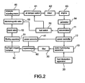
- Figure 2 is a schematic view showing a hydrogen-oxygen fuel supplying system in accordance with a second embodiment.
- the present invention provides a hydrogen-oxygen fuel supplying system, which includes a hydrolyzing apparatus 10, a heat dissipation apparatus 20, a filter 30, a supercharger 40, a hydrogen-oxygen container 50, and a pressure adjusting means 60.
- the hydrolyzing apparatus 10 includes a water electrolysis bath and two electrode plates disposed in the electrolysis bath.
- the two electrode plates hydrolyze the water into a mixture gas of hydrogen, oxygen and water vapor.
- the two electrode plates are honeycomb shaped, that is a number of gas holes are distributed in the two electrode plates just like a honeycomb.
- the honeycomb shaped electrodes can maximize surface area of the two electrode plates thereby improving output of hydrogen and oxygen when water is hydrolyzed.
- a water pressure balancer (not shown) can be mounted in the hydrolyzing apparatus 10.
- the water pressure balancer is configured for balancing pressure of hydrogen and oxygen when hydrogen and oxygen are stored separately.
- the heat dissipation apparatus 20 is mounted on a surface of the hydrolyzing apparatus 10.
- the heat dissipation apparatus 20 is used to dissipate heat generated in the hydrolyzing apparatus. Specifically, the heat dissipation apparatus 20 starts to dissipate heat when the temperature in the hydrolyzing apparatus 10 is higher than a predetermined value, and the heat dissipation apparatus 20 is shut down when the temperature in the hydrolyzing apparatus 10 is lower that the predetermined value.
- the heat dissipation apparatus 20 includes water-cooling pipes, fan, and temperature controlling member.
- the filter 30, which is connected to the hydrolyzing apparatus 10, is configured for filtering water vapor in the hydrolyzed mixture gas thereby purifying hydrogen and oxygen.
- the supercharger 40 which is used to compress the hydrogen and oxygen come from the filter 30, is connected to the filter.
- the hydrogen-oxygen container 50 is connected to the supercharger 40.
- the hydrogen-oxygen container 50 is used to store compressed hydrogen and oxygen.
- the hydrogen-oxygen container 50 may include a hydrogen storing chamber and an oxygen storing chamber defined therein. The hydrogen storing chamber and the oxygen storing chamber can be used to storing hydrogen and oxygen respectively.
- the pressure adjusting means 60 is connected to the hydrogen-oxygen container 50, and is configured for adjusting output pressure of the hydrogen and oxygen.
- the hydrogen-oxygen fuel supplying system can be connected to an engine 63 (please referring to Figure 2 ).
- the hydrogen-oxygen fuel supplying system supplies hydrogen and oxygen fuel to the engine 63 thereby driving the engine 63 to work and provide power; therefore, the present invention utilize environment friendly water as fuel source, cost of fuel and air pollution caused by organic fuel can be reduced.
- the present embodiment can further include an accumulator 11, a power controller 12, a power converter 41, a filtering apparatus 51, a check valve 52, an electromagnetic valve 53, an air damper switch 61 and a mixer 62.
- the accumulator 11 is electrically connected to the hydrolyzing apparatus 10.
- the accumulator 11 is configured for providing a portion of electrical power to the hydrolyzing apparatus 10.
- the power controller 12 is electrically connected to the accumulator 11 and the hydrolyzing apparatus 10.
- the power controller 12 is used to improve and stabilize the output of electrical power.
- the power controller 12 is consisting of a capacitor and an electrical voltage regulator.
- the power converter 41 is connected to the supercharger 40 for converting a high output voltage of the accumulator 11 to a relative low voltage.
- the output voltage of the accumulator 11 equals to 36 volts
- the power converter 41 converts the output voltage of 36 volts to 12 volts.
- the power converter 41 is a voltage regulator.
- the filtering apparatus 51 is connected to the hydrogen-oxygen container 50.
- the filtering apparatus 51 further filters water vapor in the mixture gas and purifies output of the hydrogen and oxygen.
- the check valve 52 is connected to the filtering apparatus 51 for preventing reflux and explosion of the mixture gas.
- the electromagnetic valve 53 which includes a value, is connected to the check valve 52.
- the air damper switch 61 is connected to the pressure adjusting means 60.
- the air damper switch 61 includes an air damper.
- the mixer 62 is connected to the air damper switch 61.
- the mixer 62 is used to fully mix the mixture gas and air introduced from outside of the mixer 62.
- the mixer 62 is consisting of an air nozzle and a vortex mixing member.
- the hydrogen-oxygen fuel supplying system of the present invention can be connected to an engine 63 (please referring to Figure 2 ).
- the hydrogen-oxygen fuel supplying system supplies gas fuel produced by mixing the mixture gas and air to the engine 63 thereby driving the engine 63 to work.
- the engine 63 drives a generator 64 to generating electrical power.
- the electrical power is returned to the accumulator 11 such that the accumulator is capable of providing electrical power uninterruptedly.
- the engine 63 can be an automobile engine, a marine engine, an aeronautic engine and etc. Therefore, the present invention utilize environment friendly water as fuel source, cost of fuel and air pollution caused by organic fuel can be reduced. Furthermore, a certain amount of electrical power is retained in the accumulator 11; the hydrogen-oxygen fuel supplying system can provide gas fuel uninterruptedly.
- the present invention can't be merely restricted in applications of engine, it is understood that the present invention can also be used in gas stove or electric water heater as fuel source.
- the present invention can be combined with the engine 63 and the generator 64 thereby constituting a water fuel engine generator, which can be employed as electric power source in home applications, commercial applications, community applications and city applications, and so much as a new generation of electric power source that can used to replace conventional power house.
- the hydrogen-oxygen fuel supplying system further includes a fuel switch 70, which is electrically connected to the accumulator 11.
- the fuel switch 70 is used to switch fuel fed into the hydrogen-oxygen fuel supplying system.
- the fuel can be one of water, gasoline, and alcohol.
- the electromagnetic valve 53, the valve and air damper of the air damper switch 61 are opened, and then the hydrogen-oxygen fuel supplying system is ready for providing hydrogen-oxygen fuel;
- the fuel switch 70 is set to a gasoline fuel mode or alcohol mode, the electromagnetic valve 53, the valve and air damper of the air damper switch 61 are closed, and then gasoline fuel or alcohol can be fed into the engine 63. Therefore, the hydrogen-oxygen fuel supplying system can also provide other fuel (gasoline for example) to the engine except providing hydrogen-oxygen fuel to the engine 63.
Landscapes
- Engineering & Computer Science (AREA)
- Chemical & Material Sciences (AREA)
- Combustion & Propulsion (AREA)
- Mechanical Engineering (AREA)
- General Engineering & Computer Science (AREA)
- Chemical Kinetics & Catalysis (AREA)
- Oil, Petroleum & Natural Gas (AREA)
- General Chemical & Material Sciences (AREA)
- Organic Chemistry (AREA)
- Inorganic Chemistry (AREA)
- Electrochemistry (AREA)
- Materials Engineering (AREA)
- Metallurgy (AREA)
- Electrolytic Production Of Non-Metals, Compounds, Apparatuses Therefor (AREA)
- Hydrogen, Water And Hydrids (AREA)
- Fuel Cell (AREA)
Claims (1)
- Système d'alimentation de carburant hydrogène-oxygène, comprenant :- un appareil d'hydrolyse d'eau (10) configuré pour hydrolyser de l'eau et produire ainsi un mélange gazeux d'hydrogène, d'oxygène et de vapeur d'eau ;- un appareil de dissipation thermique (20) relié à l'appareil d'hydrolyse d'eau (10), l'appareil de dissipation thermique (20) étant configuré pour dissiper la chaleur générée dans l'appareil d'hydrolyse d'eau (10) ;- un filtre (30) relié à l'appareil d'hydrolyse d'eau (10), le filtre (30) étant configuré pour filtrer la vapeur d'eau dans le mélange gazeux ;- un compresseur (40) relié au filtre, le compresseur (40) étant configuré pour comprimer l'hydrogène et l'oxygène ;- un conteneur hydrogène-oxygène (50) relié au compresseur (14), le conteneur hydrogène-oxygène (50) étant configuré pour stocker l'hydrogène et l'oxygène ;- un moyen d'ajustement de pression (60) relié au conteneur hydrogène-oxygène (50), le moyen d'ajustement de pression (60) étant configuré pour réguler une sortie d'hydrogène et d'oxygène ;- un accumulateur (11) connecté électriquement à l'appareil d'hydrolyse d'eau (10),- un contrôleur de puissance (12) connecté à l'appareil d'hydrolyse d'eau (10), ledit contrôleur de puissance (12) étant configuré pour améliorer et stabiliser la sortie de puissance électrique ;- un convertisseur de puissance (12) connecté au compresseur (14), ledit convertisseur de puissance (41) étant configuré pour convertir un voltage de sortie de l'accumulateur vers un voltage relativement bas,- un appareil de filtration (51) relié au conteneur hydrogène-oxygène (50), tel que l'appareil de filtration (51) est configuré pour filtrer la vapeur d'eau dans le mélange gazeux stocké dans le conteneur hydrogène-oxygène (50) et purifier une sortie du conteneur hydrogène-oxygène (50) ;- un clapet anti-retour (52) relié à l'appareil de filtration (51), ledit clapet anti-retour (51) étant configuré pour empêcher un reflux du mélange gazeux ;- une valve électromagnétique (53) connectée au clapet anti-retour (52) ;- un commutateur de volet d'air (61) connecté au moyen d'ajustement de pression (60), et- un mélangeur (62) connecté au commutateur de volet d'air (61), tel que le mélangeur (62) est configuré pour mélanger le mélange gazeux et de l'air.
Applications Claiming Priority (1)
| Application Number | Priority Date | Filing Date | Title |
|---|---|---|---|
| TW097106783A TW200936512A (en) | 2008-02-27 | 2008-02-27 | Water energy fuel supply system |
Publications (2)
| Publication Number | Publication Date |
|---|---|
| EP2096283A1 EP2096283A1 (fr) | 2009-09-02 |
| EP2096283B1 true EP2096283B1 (fr) | 2010-06-16 |
Family
ID=40445151
Family Applications (1)
| Application Number | Title | Priority Date | Filing Date |
|---|---|---|---|
| EP09002692A Active EP2096283B1 (fr) | 2008-02-27 | 2009-02-25 | Dispositif d'alimentation en Oxygène et Hydrogène |
Country Status (12)
| Country | Link |
|---|---|
| EP (1) | EP2096283B1 (fr) |
| JP (1) | JP2009203555A (fr) |
| KR (1) | KR101150230B1 (fr) |
| AT (1) | ATE471445T1 (fr) |
| AU (1) | AU2009200785B2 (fr) |
| BR (1) | BRPI0900317A2 (fr) |
| CA (1) | CA2655558C (fr) |
| DE (1) | DE602009000041D1 (fr) |
| MY (1) | MY147552A (fr) |
| NZ (1) | NZ575174A (fr) |
| SG (1) | SG155154A1 (fr) |
| TW (1) | TW200936512A (fr) |
Families Citing this family (2)
| Publication number | Priority date | Publication date | Assignee | Title |
|---|---|---|---|---|
| CN107435601A (zh) * | 2017-06-29 | 2017-12-05 | 广西启明氢能源有限公司 | 醇‑氢混合燃料动力系统 |
| KR102903664B1 (ko) | 2023-09-11 | 2025-12-22 | 한국수력원자력 주식회사 | 수전해 생산 수소의 고순도 저장을 위한 수소 저장탱크 및 이를 구비한 수전해 시스템 |
Family Cites Families (15)
| Publication number | Priority date | Publication date | Assignee | Title |
|---|---|---|---|---|
| IT1219506B (it) * | 1988-03-18 | 1990-05-18 | Renato Mandarini | Procedimento e apparecchiatura per diminuire sensibilmente il consumo di combustibile e i prodotti inquinanti l'ambiente nei motori a combustione interna e nelle combustioni |
| JPH07233493A (ja) * | 1994-02-22 | 1995-09-05 | Mitsubishi Heavy Ind Ltd | 水電解システム用電力変換装置 |
| US5900330A (en) * | 1997-09-25 | 1999-05-04 | Kagatani; Takeo | Power device |
| JP3719178B2 (ja) * | 2001-09-13 | 2005-11-24 | ソニー株式会社 | 水素ガス製造充填装置及び電気化学装置 |
| JP2004124148A (ja) * | 2002-10-01 | 2004-04-22 | Mitsubishi Heavy Ind Ltd | 発生水素の圧力制御方法及び水素発生装置 |
| KR200317613Y1 (ko) | 2003-03-21 | 2003-06-25 | 주식회사 디이텍 | 대용량 브라운가스 발생 및 연소장치 |
| US7150927B2 (en) * | 2003-09-10 | 2006-12-19 | Bloom Energy Corporation | SORFC system with non-noble metal electrode compositions |
| JP3836833B2 (ja) * | 2003-11-11 | 2006-10-25 | 山口 嘉春 | 水素と酸素の混合ガス発生装置およびその電解槽 |
| US7401578B2 (en) | 2004-05-21 | 2008-07-22 | Gemini Energy Technologies, Inc. | System and method for the co-generation of fuel having a closed-loop energy cycle |
| US7273044B2 (en) | 2004-09-27 | 2007-09-25 | Flessner Stephen M | Hydrogen fuel system for an internal combustion engine |
| US7100542B2 (en) * | 2004-11-04 | 2006-09-05 | Ehresoft Technologies, Inc. | Hydrogen oxygen generation system for an internal combustion engine |
| US7727647B2 (en) * | 2006-06-12 | 2010-06-01 | Honeywell International Inc. | Portable hydrogen fuel container charger |
| JP2007100204A (ja) * | 2005-10-07 | 2007-04-19 | Mitsubishi Corp | 高圧水素の製造方法および製造装置 |
| CA2576682A1 (fr) | 2006-03-08 | 2007-09-08 | Martinrea International Inc. | Systeme d'application d'electrolyte |
| KR100794759B1 (ko) * | 2006-04-24 | 2008-01-21 | 구동회 | 복합 에너지 발생시스템 |
-
2008
- 2008-02-27 TW TW097106783A patent/TW200936512A/zh unknown
-
2009
- 2009-02-25 DE DE602009000041T patent/DE602009000041D1/de active Active
- 2009-02-25 EP EP09002692A patent/EP2096283B1/fr active Active
- 2009-02-25 CA CA2655558A patent/CA2655558C/fr not_active Expired - Fee Related
- 2009-02-25 AT AT09002692T patent/ATE471445T1/de not_active IP Right Cessation
- 2009-02-26 AU AU2009200785A patent/AU2009200785B2/en not_active Expired - Fee Related
- 2009-02-26 NZ NZ575174A patent/NZ575174A/en not_active IP Right Cessation
- 2009-02-26 MY MYPI20090785A patent/MY147552A/en unknown
- 2009-02-26 SG SG200901474-7A patent/SG155154A1/en unknown
- 2009-02-27 JP JP2009046610A patent/JP2009203555A/ja active Pending
- 2009-02-27 BR BRPI0900317-7A patent/BRPI0900317A2/pt not_active IP Right Cessation
- 2009-02-27 KR KR1020090016940A patent/KR101150230B1/ko not_active Expired - Fee Related
Also Published As
| Publication number | Publication date |
|---|---|
| CA2655558C (fr) | 2012-01-03 |
| EP2096283A1 (fr) | 2009-09-02 |
| CA2655558A1 (fr) | 2009-08-27 |
| AU2009200785B2 (en) | 2010-11-18 |
| AU2009200785A1 (en) | 2009-09-10 |
| KR20090092734A (ko) | 2009-09-01 |
| NZ575174A (en) | 2010-09-30 |
| JP2009203555A (ja) | 2009-09-10 |
| ATE471445T1 (de) | 2010-07-15 |
| SG155154A1 (en) | 2009-09-30 |
| BRPI0900317A2 (pt) | 2010-10-26 |
| DE602009000041D1 (de) | 2010-07-29 |
| MY147552A (en) | 2012-12-31 |
| KR101150230B1 (ko) | 2012-05-24 |
| TW200936512A (en) | 2009-09-01 |
Similar Documents
| Publication | Publication Date | Title |
|---|---|---|
| CN211364899U (zh) | 一种船用制氢供氢一体化氢能动力系统 | |
| US20100206646A1 (en) | Oxyhydrogen vehicle | |
| CN109606600A (zh) | 一种船舶用可再生能源混合动力系统 | |
| US20070012264A1 (en) | Water fuel convertor | |
| CN102094733B (zh) | 汽车节油减排装置 | |
| US7921831B2 (en) | Hydrogen-oxygen fuel supplying system | |
| CA2655558C (fr) | Systeme d'alimentation en combustible oxygene/hydrogene | |
| KR100880413B1 (ko) | 홈형쏠라쎌모듈 및 금속화합물촉매를 이용한 수소생산엔진연료화 시스템. | |
| WO2025241498A1 (fr) | Procédé de fonctionnement pour système couplé de stockage d'énergie par air comprimé et d'énergie hydrogène | |
| CN118597392B (zh) | 一种零排放氢能动力船舶系统及其应用的船舶 | |
| CN111942137A (zh) | 汽车用混合动力系统及其使用方法和使用该系统的汽车 | |
| TW201008802A (en) | Environment friendly oxyhydrogen vehicle with multi-electric power sources | |
| KR101122567B1 (ko) | 연료전지와 가스 내연기관을 혼용한 선박 발전장비 | |
| CN201934216U (zh) | 汽车节油减排装置 | |
| CN101525753B (zh) | 水能源燃料供给系统 | |
| CN215220773U (zh) | 一种醇氢燃料动力系统及发电装置 | |
| CN201287626Y (zh) | 具多方电力源的环保氢氧车 | |
| CN201314264Y (zh) | 一种汽车制氢燃油节能设备 | |
| CN114644101A (zh) | 一种带电解槽的船舶气电混合动力系统 | |
| US8753781B2 (en) | Fuel provision system | |
| CN219268502U (zh) | 一种风光电制氢储能热电氧三联供的系统 | |
| CN201678737U (zh) | 汽车太阳能电解水氢氧节油装置 | |
| TWM296307U (en) | Energy supply system for internal combustion engine | |
| CN117294026B (zh) | 基于氩气动力循环氢气机的高效清洁储能发电系统及方法 | |
| EP2728664A1 (fr) | Système de fourniture de carburant |
Legal Events
| Date | Code | Title | Description |
|---|---|---|---|
| PUAI | Public reference made under article 153(3) epc to a published international application that has entered the european phase |
Free format text: ORIGINAL CODE: 0009012 |
|
| 17P | Request for examination filed |
Effective date: 20090612 |
|
| AK | Designated contracting states |
Kind code of ref document: A1 Designated state(s): AT BE BG CH CY CZ DE DK EE ES FI FR GB GR HR HU IE IS IT LI LT LU LV MC MK MT NL NO PL PT RO SE SI SK TR |
|
| AX | Request for extension of the european patent |
Extension state: AL BA RS |
|
| GRAP | Despatch of communication of intention to grant a patent |
Free format text: ORIGINAL CODE: EPIDOSNIGR1 |
|
| AKX | Designation fees paid |
Designated state(s): AT BE BG CH CY CZ DE DK EE ES FI FR GB GR HR HU IE IS IT LI LT LU LV MC MK MT NL NO PL PT RO SE SI SK TR |
|
| GRAS | Grant fee paid |
Free format text: ORIGINAL CODE: EPIDOSNIGR3 |
|
| GRAA | (expected) grant |
Free format text: ORIGINAL CODE: 0009210 |
|
| AK | Designated contracting states |
Kind code of ref document: B1 Designated state(s): AT BE BG CH CY CZ DE DK EE ES FI FR GB GR HR HU IE IS IT LI LT LU LV MC MK MT NL NO PL PT RO SE SI SK TR |
|
| REG | Reference to a national code |
Ref country code: CH Ref legal event code: EP |
|
| REG | Reference to a national code |
Ref country code: IE Ref legal event code: FG4D |
|
| REF | Corresponds to: |
Ref document number: 602009000041 Country of ref document: DE Date of ref document: 20100729 Kind code of ref document: P |
|
| REG | Reference to a national code |
Ref country code: SE Ref legal event code: TRGR |
|
| REG | Reference to a national code |
Ref country code: NL Ref legal event code: VDEP Effective date: 20100616 |
|
| PG25 | Lapsed in a contracting state [announced via postgrant information from national office to epo] |
Ref country code: LT Free format text: LAPSE BECAUSE OF FAILURE TO SUBMIT A TRANSLATION OF THE DESCRIPTION OR TO PAY THE FEE WITHIN THE PRESCRIBED TIME-LIMIT Effective date: 20100616 Ref country code: NO Free format text: LAPSE BECAUSE OF FAILURE TO SUBMIT A TRANSLATION OF THE DESCRIPTION OR TO PAY THE FEE WITHIN THE PRESCRIBED TIME-LIMIT Effective date: 20100916 |
|
| LTIE | Lt: invalidation of european patent or patent extension |
Effective date: 20100616 |
|
| PG25 | Lapsed in a contracting state [announced via postgrant information from national office to epo] |
Ref country code: SI Free format text: LAPSE BECAUSE OF FAILURE TO SUBMIT A TRANSLATION OF THE DESCRIPTION OR TO PAY THE FEE WITHIN THE PRESCRIBED TIME-LIMIT Effective date: 20100616 Ref country code: LV Free format text: LAPSE BECAUSE OF FAILURE TO SUBMIT A TRANSLATION OF THE DESCRIPTION OR TO PAY THE FEE WITHIN THE PRESCRIBED TIME-LIMIT Effective date: 20100616 Ref country code: HR Free format text: LAPSE BECAUSE OF FAILURE TO SUBMIT A TRANSLATION OF THE DESCRIPTION OR TO PAY THE FEE WITHIN THE PRESCRIBED TIME-LIMIT Effective date: 20100616 Ref country code: FI Free format text: LAPSE BECAUSE OF FAILURE TO SUBMIT A TRANSLATION OF THE DESCRIPTION OR TO PAY THE FEE WITHIN THE PRESCRIBED TIME-LIMIT Effective date: 20100616 Ref country code: AT Free format text: LAPSE BECAUSE OF FAILURE TO SUBMIT A TRANSLATION OF THE DESCRIPTION OR TO PAY THE FEE WITHIN THE PRESCRIBED TIME-LIMIT Effective date: 20100616 |
|
| PG25 | Lapsed in a contracting state [announced via postgrant information from national office to epo] |
Ref country code: PL Free format text: LAPSE BECAUSE OF FAILURE TO SUBMIT A TRANSLATION OF THE DESCRIPTION OR TO PAY THE FEE WITHIN THE PRESCRIBED TIME-LIMIT Effective date: 20100616 Ref country code: CY Free format text: LAPSE BECAUSE OF FAILURE TO SUBMIT A TRANSLATION OF THE DESCRIPTION OR TO PAY THE FEE WITHIN THE PRESCRIBED TIME-LIMIT Effective date: 20100616 |
|
| PG25 | Lapsed in a contracting state [announced via postgrant information from national office to epo] |
Ref country code: EE Free format text: LAPSE BECAUSE OF FAILURE TO SUBMIT A TRANSLATION OF THE DESCRIPTION OR TO PAY THE FEE WITHIN THE PRESCRIBED TIME-LIMIT Effective date: 20100616 Ref country code: NL Free format text: LAPSE BECAUSE OF FAILURE TO SUBMIT A TRANSLATION OF THE DESCRIPTION OR TO PAY THE FEE WITHIN THE PRESCRIBED TIME-LIMIT Effective date: 20100616 |
|
| PG25 | Lapsed in a contracting state [announced via postgrant information from national office to epo] |
Ref country code: IS Free format text: LAPSE BECAUSE OF FAILURE TO SUBMIT A TRANSLATION OF THE DESCRIPTION OR TO PAY THE FEE WITHIN THE PRESCRIBED TIME-LIMIT Effective date: 20101016 Ref country code: BE Free format text: LAPSE BECAUSE OF FAILURE TO SUBMIT A TRANSLATION OF THE DESCRIPTION OR TO PAY THE FEE WITHIN THE PRESCRIBED TIME-LIMIT Effective date: 20100616 Ref country code: SK Free format text: LAPSE BECAUSE OF FAILURE TO SUBMIT A TRANSLATION OF THE DESCRIPTION OR TO PAY THE FEE WITHIN THE PRESCRIBED TIME-LIMIT Effective date: 20100616 Ref country code: RO Free format text: LAPSE BECAUSE OF FAILURE TO SUBMIT A TRANSLATION OF THE DESCRIPTION OR TO PAY THE FEE WITHIN THE PRESCRIBED TIME-LIMIT Effective date: 20100616 Ref country code: CZ Free format text: LAPSE BECAUSE OF FAILURE TO SUBMIT A TRANSLATION OF THE DESCRIPTION OR TO PAY THE FEE WITHIN THE PRESCRIBED TIME-LIMIT Effective date: 20100616 |
|
| PLBE | No opposition filed within time limit |
Free format text: ORIGINAL CODE: 0009261 |
|
| STAA | Information on the status of an ep patent application or granted ep patent |
Free format text: STATUS: NO OPPOSITION FILED WITHIN TIME LIMIT |
|
| PG25 | Lapsed in a contracting state [announced via postgrant information from national office to epo] |
Ref country code: DK Free format text: LAPSE BECAUSE OF FAILURE TO SUBMIT A TRANSLATION OF THE DESCRIPTION OR TO PAY THE FEE WITHIN THE PRESCRIBED TIME-LIMIT Effective date: 20100616 |
|
| 26N | No opposition filed |
Effective date: 20110317 |
|
| PG25 | Lapsed in a contracting state [announced via postgrant information from national office to epo] |
Ref country code: GR Free format text: LAPSE BECAUSE OF FAILURE TO SUBMIT A TRANSLATION OF THE DESCRIPTION OR TO PAY THE FEE WITHIN THE PRESCRIBED TIME-LIMIT Effective date: 20100917 |
|
| REG | Reference to a national code |
Ref country code: DE Ref legal event code: R097 Ref document number: 602009000041 Country of ref document: DE Effective date: 20110316 |
|
| PG25 | Lapsed in a contracting state [announced via postgrant information from national office to epo] |
Ref country code: MC Free format text: LAPSE BECAUSE OF NON-PAYMENT OF DUE FEES Effective date: 20110228 |
|
| REG | Reference to a national code |
Ref country code: IE Ref legal event code: MM4A |
|
| PG25 | Lapsed in a contracting state [announced via postgrant information from national office to epo] |
Ref country code: MT Free format text: LAPSE BECAUSE OF FAILURE TO SUBMIT A TRANSLATION OF THE DESCRIPTION OR TO PAY THE FEE WITHIN THE PRESCRIBED TIME-LIMIT Effective date: 20100616 |
|
| PG25 | Lapsed in a contracting state [announced via postgrant information from national office to epo] |
Ref country code: IE Free format text: LAPSE BECAUSE OF NON-PAYMENT OF DUE FEES Effective date: 20110225 |
|
| PGFP | Annual fee paid to national office [announced via postgrant information from national office to epo] |
Ref country code: IT Payment date: 20120228 Year of fee payment: 4 |
|
| PGFP | Annual fee paid to national office [announced via postgrant information from national office to epo] |
Ref country code: SE Payment date: 20130226 Year of fee payment: 5 Ref country code: DE Payment date: 20130228 Year of fee payment: 5 Ref country code: FR Payment date: 20130318 Year of fee payment: 5 Ref country code: GB Payment date: 20130225 Year of fee payment: 5 |
|
| PG25 | Lapsed in a contracting state [announced via postgrant information from national office to epo] |
Ref country code: LU Free format text: LAPSE BECAUSE OF NON-PAYMENT OF DUE FEES Effective date: 20110225 |
|
| PG25 | Lapsed in a contracting state [announced via postgrant information from national office to epo] |
Ref country code: PT Free format text: LAPSE BECAUSE OF NON-PAYMENT OF DUE FEES Effective date: 20100616 |
|
| PG25 | Lapsed in a contracting state [announced via postgrant information from national office to epo] |
Ref country code: TR Free format text: LAPSE BECAUSE OF FAILURE TO SUBMIT A TRANSLATION OF THE DESCRIPTION OR TO PAY THE FEE WITHIN THE PRESCRIBED TIME-LIMIT Effective date: 20100616 Ref country code: BG Free format text: LAPSE BECAUSE OF FAILURE TO SUBMIT A TRANSLATION OF THE DESCRIPTION OR TO PAY THE FEE WITHIN THE PRESCRIBED TIME-LIMIT Effective date: 20100916 |
|
| REG | Reference to a national code |
Ref country code: CH Ref legal event code: PL |
|
| PG25 | Lapsed in a contracting state [announced via postgrant information from national office to epo] |
Ref country code: HU Free format text: LAPSE BECAUSE OF FAILURE TO SUBMIT A TRANSLATION OF THE DESCRIPTION OR TO PAY THE FEE WITHIN THE PRESCRIBED TIME-LIMIT Effective date: 20100616 Ref country code: LI Free format text: LAPSE BECAUSE OF NON-PAYMENT OF DUE FEES Effective date: 20130228 Ref country code: CH Free format text: LAPSE BECAUSE OF NON-PAYMENT OF DUE FEES Effective date: 20130228 Ref country code: ES Free format text: LAPSE BECAUSE OF FAILURE TO SUBMIT A TRANSLATION OF THE DESCRIPTION OR TO PAY THE FEE WITHIN THE PRESCRIBED TIME-LIMIT Effective date: 20100927 |
|
| REG | Reference to a national code |
Ref country code: DE Ref legal event code: R119 Ref document number: 602009000041 Country of ref document: DE |
|
| REG | Reference to a national code |
Ref country code: SE Ref legal event code: EUG |
|
| GBPC | Gb: european patent ceased through non-payment of renewal fee |
Effective date: 20140225 |
|
| REG | Reference to a national code |
Ref country code: FR Ref legal event code: ST Effective date: 20141031 |
|
| PG25 | Lapsed in a contracting state [announced via postgrant information from national office to epo] |
Ref country code: SE Free format text: LAPSE BECAUSE OF NON-PAYMENT OF DUE FEES Effective date: 20140226 |
|
| REG | Reference to a national code |
Ref country code: DE Ref legal event code: R119 Ref document number: 602009000041 Country of ref document: DE Effective date: 20140902 |
|
| PG25 | Lapsed in a contracting state [announced via postgrant information from national office to epo] |
Ref country code: GB Free format text: LAPSE BECAUSE OF NON-PAYMENT OF DUE FEES Effective date: 20140225 Ref country code: DE Free format text: LAPSE BECAUSE OF NON-PAYMENT OF DUE FEES Effective date: 20140902 Ref country code: FR Free format text: LAPSE BECAUSE OF NON-PAYMENT OF DUE FEES Effective date: 20140228 |
|
| PG25 | Lapsed in a contracting state [announced via postgrant information from national office to epo] |
Ref country code: IT Free format text: LAPSE BECAUSE OF NON-PAYMENT OF DUE FEES Effective date: 20140225 |