EP2096306A1 - Procédé destiné à l'utilisation de l'énergie géothermique, en particulier pour la production de courant - Google Patents
Procédé destiné à l'utilisation de l'énergie géothermique, en particulier pour la production de courant Download PDFInfo
- Publication number
- EP2096306A1 EP2096306A1 EP08003446A EP08003446A EP2096306A1 EP 2096306 A1 EP2096306 A1 EP 2096306A1 EP 08003446 A EP08003446 A EP 08003446A EP 08003446 A EP08003446 A EP 08003446A EP 2096306 A1 EP2096306 A1 EP 2096306A1
- Authority
- EP
- European Patent Office
- Prior art keywords
- thermal barrier
- heat
- soil
- transfer medium
- geothermal
- Prior art date
- Legal status (The legal status is an assumption and is not a legal conclusion. Google has not performed a legal analysis and makes no representation as to the accuracy of the status listed.)
- Withdrawn
Links
Images
Classifications
-
- F—MECHANICAL ENGINEERING; LIGHTING; HEATING; WEAPONS; BLASTING
- F03—MACHINES OR ENGINES FOR LIQUIDS; WIND, SPRING, OR WEIGHT MOTORS; PRODUCING MECHANICAL POWER OR A REACTIVE PROPULSIVE THRUST, NOT OTHERWISE PROVIDED FOR
- F03G—SPRING, WEIGHT, INERTIA OR LIKE MOTORS; MECHANICAL-POWER PRODUCING DEVICES OR MECHANISMS, NOT OTHERWISE PROVIDED FOR OR USING ENERGY SOURCES NOT OTHERWISE PROVIDED FOR
- F03G4/00—Devices for producing mechanical power from geothermal energy
- F03G4/074—Safety arrangements
-
- Y—GENERAL TAGGING OF NEW TECHNOLOGICAL DEVELOPMENTS; GENERAL TAGGING OF CROSS-SECTIONAL TECHNOLOGIES SPANNING OVER SEVERAL SECTIONS OF THE IPC; TECHNICAL SUBJECTS COVERED BY FORMER USPC CROSS-REFERENCE ART COLLECTIONS [XRACs] AND DIGESTS
- Y02—TECHNOLOGIES OR APPLICATIONS FOR MITIGATION OR ADAPTATION AGAINST CLIMATE CHANGE
- Y02E—REDUCTION OF GREENHOUSE GAS [GHG] EMISSIONS, RELATED TO ENERGY GENERATION, TRANSMISSION OR DISTRIBUTION
- Y02E10/00—Energy generation through renewable energy sources
- Y02E10/10—Geothermal energy
Definitions
- the invention relates to a method for the use of geothermal energy, in particular for power generation.
- the invention is therefore based on the technical problem of specifying a method with which heat energy can be transported away from geothermal sources and with which the geothermal sources can be used as long as possible.
- the invention teaches a method for using geothermal heat, in particular for power generation, geothermal heat is conveyed away via at least one delivery line from an underground area, above the underground area at least partially a planar heat barrier is arranged with the proviso that a Heat radiation or heat dissipation from the below the thermal barrier arranged underground area or soil in the direction of the earth's surface is reduced or minimized.
- the thermal barrier is provided underground or below the earth's surface.
- Soil means in the context of the invention, especially rock and especially crystalline rock, such as granite or gneiss. With soil but also highly permeable rock layers, so-called aquifers are meant.
- soil further includes within the scope of the invention also so-called fault zones. These are fracture zones or fracture surfaces that can occur in sedimentary rocks such as crystalline rock.
- a particularly preferred embodiment of the method according to the invention is characterized in that a heat transfer medium is introduced through at least one supply line in the underground area or in the soil and exiting from at least one outlet opening of the supply line into the soil, wherein the heat transfer medium from the outlet opening over a flow distance s the soil penetrating to at least one discharge opening at least one delivery line is guided and is conveyed away from the conveyor line from the underground area, above the subterranean area or above the flow area between the outlet opening and discharge opening at least partially the areal heat barrier is arranged.
- the flow distance s is preferably the horizontal distance between the outlet opening and the discharge opening or between the outlet opening and the delivery line.
- Flow region in the context of the invention means the region of the soil in which the heat transfer medium flows from the outlet opening to the discharge opening.
- Flow direction means in the frame the invention, the direction of the outlet opening to the discharge opening. It has been proven to artificially break up the soil in the flow area in order to reduce the flow resistance of the heat transfer medium.
- the outlet opening and the discharge opening for the heat transfer medium are expediently arranged at a depth of 1,500 m to 7,000 m, preferably from 2,000 m to 7,000 m, and preferably from 3,000 m to 7,000 m. According to a very preferred embodiment of the invention, the outlet opening and / or the discharge opening is provided at a depth of 3,500 m to 6,000 m.
- the flow distance s is at least 200 m, preferably at least 300 m and preferably at least 400 m. Conveniently, the flow distance is up to 800 m and recommended up to 600 m.
- the thermal barrier is introduced into the soil.
- the thermal barrier is preferably introduced at a depth into the soil in which the temperature of the soil 80 ° C to 250 ° C, preferably 120 ° C to 240 ° C, very preferably 150 ° C to 230 ° C and particularly preferably 160 ° C. up to 220 ° C.
- the thermal barrier is introduced with the proviso in the soil that sets a temperature of 130 ° C to 280 ° C by heat accumulation in the area below the thermal barrier, preferably a temperature of 140 ° C to 260 ° C, preferably from 150 ° C to 230 ° C, and more preferably from 170 ° C to 210 ° C.
- Area below the thermal barrier means the range of 0 to 500 m, preferably from 1 to 200 m and preferably from 1 to 100 m below the thermal barrier.
- the inventive method is recommended carried out with the proviso that the conveyed to the earth's surface heat transfer medium has a temperature of 140 ° C to 200 ° C, suitably from 150 ° C to 190 ° C and preferably from 160 ° C to 180 ° C.
- the thermal barrier at a depth of 400 m to 6,000 m, preferably 1,500 m to 5,500 m, preferably 3,000 to 5,000 m, and preferably 4,000 to 5,000 m introduced into the soil.
- the thickness d of the thermal barrier is preferably 1 to 20 m, preferably 1 to 15 m, very preferably 1 to 8 m. Thickness d of the thermal barrier means in the context of the invention, the expansion of the thermal barrier in the vertical direction or in the direction transverse to the earth's surface.
- the soil is preferably exposed to vibrations, whereby cavities or cracks are formed in the soil.
- the material of the thermal barrier is filled or pressed.
- at least one vertical or substantially vertical fragmentation bore is preferably driven into the ground. It has been proven that at least one horizontal or substantially horizontal detonation bore adjoins the fragmentation bore.
- the cavitation or the fragmenting of the soil is recommended carried out by the ignition of explosive charges in the fragmentation and / or blast hole and / or by the injection of liquid under high pressure (hydraulic-factoring method) through the fragmentation and / or blast hole.
- An embodiment of the method is characterized in that lances in the soil of the Surface are introduced, through which lances the material of the thermal barrier is pressed into the soil.
- a thermal barrier according to the invention of a introduced into the ground shaft in particular of a vertically introduced into the ground shaft, by means of holes and / or lances in the ground is arranged.
- the introduction of the thermal barrier or the material of the thermal barrier expediently takes place from the shaft bottom.
- the shaft floor may be located, for example, at a depth of 600 m to 1,000 m.
- the shaft is an already existing shaft, in particular a mine or mining shaft.
- the length I of the thermal barrier in the flow direction is at least 1/10 of the flow distance s, preferably at least 1/5 and preferably at least 1/2 of the flow distance s. It has been proven that the thermal barrier is preferably arranged vertically above the flow region. In a further embodiment of the invention, the length I of the thermal barrier is at least 1 s, preferably at least 1.5 s. If the length I of the thermal barrier is more than s, then the flow region is preferably completely or substantially completely vertically below the thermal barrier.
- the width b of the thermal barrier (transverse to the flow direction) is at least 1/20 of the flow distance s, preferably at least 1/15 and preferably at least 1/10 of the flow distance s.
- An embodiment of the invention is characterized in that the width b of the thermal barrier is at least 1/4 s and preferably at least 1/2 s.
- the width b, the length I and the thickness d define the extent and volume of the thermal barrier.
- An embodiment of the invention is characterized in that the material of the thermal barrier is pressed into cavities or cracks of the fragmented soil at at least two press-fit points.
- a plurality of subunits are formed, preferably at least three, preferably at least five subunits. Due to statistical voiding or cracking, the subunits typically have a statistical three-dimensional geometry. It is within the scope of the invention that the subunits are each configured cloud-shaped. Preferably, the subunits are arranged in one plane or substantially in one plane. Basically, the thickness of the subunits is as large or about as large as the thickness d of the thermal barrier.
- the thermal barrier has a coverage of at least 20%, preferably of at least 30% and preferably has a coverage of at least 40%.
- the area covered by the subunits is first determined. This covered area corresponds to the area covered by the subunits as they are projected onto a horizontal plane in this plane as a whole.
- the square of the flow distance s is used as the reference surface for determining the areal coverage.
- the area coverage ratio results from the quotient of the coverage area of the subunits and the reference area s 2 .
- a plurality of subunits are arranged substantially at least in part in a first plane at a distance from each other, and a plurality of subunits is also arranged at least partially spaced apart in a second plane and the subunits of the second Level are at least partially arranged offset to the subunits of the first level, so that the distances or gaps in the first plane are at least partially covered or covered by the subunits of the second level. It is within the scope of the invention to arrange a plurality of such levels with subunits one above the other, wherein preferably the subunits of the respective adjacent planes are at least partially offset from each other, so that the distances or gaps of the adjacent plane are at least partially covered or covered.
- the thermal barrier consists at least for the most part of a heat-insulating or heat-insulating material.
- the material of the thermal barrier at least partially at least one plastic, preferably a high temperature resistant plastic. Empfohleneschreib the thermal barrier or its subunits to at least 90 wt .-%, preferably at least 95 wt .-% of plastic.
- the thermal barrier or its subunits completely or substantially consists of plastic.
- the material of the thermal barrier is suitably selected with the proviso that the coefficient of thermal conductivity of the material is smaller than that of the soil surrounding the thermal barrier. It is recommended that at least one plastic is used, which is stable to temperatures of 80 ° C to 130 ° C or long-term stability. Preferably, at least one stabilizer is added to the plastic, which increases the heat stability of the plastic.
- a foamable plastic is used as the plastic for the thermal barrier.
- at least one plastic selected from the group "polyamide, polyethersulfone, polyethylene terephthalate, polyimide, polystyrene" for the material of the thermal barrier.
- any material for the thermal barrier can be used within the scope of the invention with which heat radiation or heat dissipation from the soil arranged below the thermal barrier can be reduced or minimized in the direction of the earth's surface.
- concrete can be used as a material for the thermal barrier or as a material for the subunits of the thermal barrier.
- At least one discharge opening of a delivery line is arranged at a lower level than the associated outlet opening of a supply line.
- the depth difference .DELTA.t between the outlet opening and discharge opening is preferably at least 1/20 of the flow distance s, preferably at least 1/15 and particularly preferably at least 1/10 of the flow distance s.
- At least two outlet openings are arranged in at least one first linear row and that at least two outlet openings are arranged in at least one parallel or substantially parallel to the first linear row arranged second linear row.
- all outlet openings of the first linear row can be connected to a single supply line.
- the distance a of the outlet openings and / or discharge openings within a linear row is 100 m to 400 m, preferably 200 m to 300 m and preferably 250 m or approximately 250 m.
- the heat transfer medium preferably enters the soil from at least one exit opening of the first linear row. It has been proven that the heat transfer medium enters the soil through at least two and preferably through a plurality of outlet openings.
- the heat transfer medium is recommended promoted by at least one discharge opening to the delivery line.
- the Heat transfer medium by at least two and preferably conveyed by a plurality of discharge openings to the delivery line.
- a preferred embodiment of the method is characterized in that a first linear row is arranged with outlet openings between two second linear rows with discharge openings.
- the three mentioned linear rows are expediently arranged parallel or substantially parallel to one another.
- the second linear rows of the first linear row have the same flow distance s.
- a particularly preferred embodiment of the invention is characterized in that it operates with at least two geothermal heat units, each having at least one supply line with at least one outlet opening and at least one delivery line with at least one discharge opening, that at least a portion of the geothermal units each assigned a thermal barrier according to the invention and that the geothermal heat units are operated alternately.
- all alternately operated geothermal units are each equipped with a thermal barrier according to the invention.
- the alternating operation of the geothermal units in combination with the thermal barriers according to the invention is of very particular importance in the context of the invention. This embodiment is characterized by a high efficiency.
- the invention is based on the finding that, with the method according to the invention, the geothermal heat can be effectively utilized in a certain ground section over a relatively long period of time.
- the thermal barrier according to the invention is of particular importance. This thermal barrier prevents the heat developed in the earth's core from being conducted unhindered to the surface where it is emitted to the atmosphere.
- the invention is based on the knowledge that with a thermal barrier according to the invention, the transmission and dissipation of the heat developed by the earth's core can be inhibited in a surprisingly simple manner. Since unwanted heat losses are reduced by the radiation of heat at the surface, the regenerability of the heat source is surprisingly effectively improved.
- the very preferred alternating promotion of the heat transfer medium allows a very effective, uniform and large-scale heat dissipation.
- thermal barrier according to the invention over known geothermal methods, a significantly higher efficiency of heat removal can be achieved.
- the heat dissipated from a certain depth or conveyed to the earth's surface has a significantly higher temperature level compared to the known methods.
- the energy conversion, in particular the generation of electrical energy, in a power plant can take place on the basis of the method according to the invention with surprisingly high efficiency.
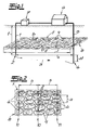
- FIG. 1 An unspecified heat transfer medium is in Fig. 1 introduced through a supply line 1 into the soil and enters through an outlet opening 2 into the soil.
- the outlet opening is at a depth t of approximately 4,000 m.
- the heat transfer medium is preferably water.
- the heat transfer medium penetrates in the exemplary embodiment Fig. 1 the soil in the flow direction 3 to a discharge opening 4, wherein the flow distance s is about 500 m.
- the recommended under high pressure heat transfer medium is heated by contact with the soil and thereby preferably evaporated.
- the heated heat transfer medium enters the delivery line 5, through which the heat transfer medium is expediently conveyed in the gaseous state to the surface. It is recommended that in an energy recovery unit 6 electrical energy is generated, wherein the heat transfer medium is preferably cooled and preferably condensed.
- the cooled heat transfer medium is expediently conducted to a pump unit 7, from where it is pressed back into the ground via the supply line 1. It has been proven that the discharge opening 4 is arranged lower than the outlet opening 2 by a difference .DELTA.t.
- the difference At is at a flow distance s of approximately 500 m, preferably at least 25 m.
- a thermal barrier 8 is shown, which is arranged in the embodiment at a depth of about 2,500 m.
- the thickness d of the thermal barrier 8 is preferably 3 to 10 m.
- the thermal barrier 8 of a plurality of cloud-shaped subunits 9 is formed, which are arranged according to an embodiment and in the embodiment in each case at a distance from each other.
- the length I of the thermal barrier 8 in the flow direction is preferably and in the embodiment greater than the flow distance s and in the exemplary embodiment is 600 m.
- the flow region through which the heat transfer medium flows between the outlet opening 2 and the discharge opening 4 is arranged completely vertically below the thermal barrier 8.
- the supply line 1 and the delivery line 5 penetrate in the exemplary embodiment Fig. 1 the thermal barrier 8, so that the outlet opening 2 and the discharge opening 4 are arranged vertically below the thermal barrier 8.
- Fig. 1 For the sake of clarity, only the projection of the cloud-shaped subunits 9 on a horizontal surface F through the thermal barrier 8 is shown.
- the areal coverage of the thermal barrier 8 is preferably and in the exemplary embodiment at least 50%, more preferably more than 50%.
- the area coverage of the thermal barrier 8 is in the embodiment in Fig. 1 about 60%.
- Fig. 2 It can be seen that, preferably and in the exemplary embodiment, a first linear row 10 of outlet openings 2 is provided and that two second linear rows 11 of discharge openings 4 are arranged symmetrically or approximately symmetrically to the right and left of this first linear row 10. Conveniently, the arranged in a row outlet openings 2 and discharge openings 4 are each at a single in Fig.
- all three linear rows 10, 11 are arranged parallel or substantially parallel to each other.
- Symmetrically means in the context of the embodiment Fig. 2 in that the flow distance s between the first row 10 and the right and left second row 11 is equal or approximately the same.
- the flow distance s is about 500 m.
- the second rows 11 are in the embodiment located about 1,000 meters apart.
- the outlet openings 2 and the discharge openings 4 in the linear rows 10, 11 are uniformly distributed and have the same or substantially equal distances from each other.
- the distance a of two outlet openings 2 or discharge openings 4 arranged side by side within a row 10, 11 amounts to approximately 250 m in the exemplary embodiment.
- a thermal barrier 8 arranged above the flow area. It has been proven that all outlet openings or discharge openings of the first and the second rows are arranged vertically below the thermal barrier 8.
- the thermal barrier is 8 in Fig. 2 about 1,200 m long and about 600 m wide.
- the thermal barrier 8 is about 10 m thick.
- the thermal barrier 8 is also formed here by a plurality of subunits 9. The pictured outline of the subunits 9 in Fig. 2 represents the projection of the subunits 9 on the horizontal plane F of the thermal barrier 8.
- the area coverage (covered area / s 2 ) is about 70%.
- the heat transfer medium is, for example, with the help of at least one in Fig. 2 Pump not shown by also in Fig. 2 conveying line 5 not shown conveyed to the earth's surface or to an energy recovery unit 6.
- this energy recovery unit 6 the heat carried by the heat transfer medium (geothermal) is converted into mechanical energy.
- the heat is preferably transferred in a heat exchanger expediently to an organic liquid which has a lower boiling point than water.
- the organic liquid is evaporated and the steam is preferably passed through at least one turbine at high temperature and high pressure.
- the turbine expediently drives a generator with which the mechanical energy is converted into electrical energy.
- the organic medium is cooled in this process, relaxed and then expediently returned to the heat exchanger, in which it is heated by means of the heat transfer medium.
- the cooled after the heat exchanger heat transfer medium is then preferably again pressed under high pressure through the supply line 1 and the outlet openings 2 into the ground.
Landscapes
- Engineering & Computer Science (AREA)
- Chemical & Material Sciences (AREA)
- Combustion & Propulsion (AREA)
- Life Sciences & Earth Sciences (AREA)
- Sustainable Energy (AREA)
- Mechanical Engineering (AREA)
- General Engineering & Computer Science (AREA)
- Engine Equipment That Uses Special Cycles (AREA)
Priority Applications (1)
| Application Number | Priority Date | Filing Date | Title |
|---|---|---|---|
| EP08003446A EP2096306A1 (fr) | 2008-02-26 | 2008-02-26 | Procédé destiné à l'utilisation de l'énergie géothermique, en particulier pour la production de courant |
Applications Claiming Priority (1)
| Application Number | Priority Date | Filing Date | Title |
|---|---|---|---|
| EP08003446A EP2096306A1 (fr) | 2008-02-26 | 2008-02-26 | Procédé destiné à l'utilisation de l'énergie géothermique, en particulier pour la production de courant |
Publications (1)
| Publication Number | Publication Date |
|---|---|
| EP2096306A1 true EP2096306A1 (fr) | 2009-09-02 |
Family
ID=39563272
Family Applications (1)
| Application Number | Title | Priority Date | Filing Date |
|---|---|---|---|
| EP08003446A Withdrawn EP2096306A1 (fr) | 2008-02-26 | 2008-02-26 | Procédé destiné à l'utilisation de l'énergie géothermique, en particulier pour la production de courant |
Country Status (1)
| Country | Link |
|---|---|
| EP (1) | EP2096306A1 (fr) |
Citations (5)
| Publication number | Priority date | Publication date | Assignee | Title |
|---|---|---|---|---|
| US3875749A (en) * | 1972-11-17 | 1975-04-08 | Petru Baciu | Geothermal power plant with high efficiency |
| US4077220A (en) * | 1976-11-09 | 1978-03-07 | Sperry Rand Corporation | Gravity head geothermal energy conversion system |
| US4201060A (en) * | 1978-08-24 | 1980-05-06 | Union Oil Company Of California | Geothermal power plant |
| US5311741A (en) * | 1992-10-09 | 1994-05-17 | Blaize Louis J | Hybrid electric power generation |
| EP1609988A1 (fr) * | 2004-06-07 | 2005-12-28 | Klaus Dr. Rennebeck | Installation geothermique naturelle |
-
2008
- 2008-02-26 EP EP08003446A patent/EP2096306A1/fr not_active Withdrawn
Patent Citations (5)
| Publication number | Priority date | Publication date | Assignee | Title |
|---|---|---|---|---|
| US3875749A (en) * | 1972-11-17 | 1975-04-08 | Petru Baciu | Geothermal power plant with high efficiency |
| US4077220A (en) * | 1976-11-09 | 1978-03-07 | Sperry Rand Corporation | Gravity head geothermal energy conversion system |
| US4201060A (en) * | 1978-08-24 | 1980-05-06 | Union Oil Company Of California | Geothermal power plant |
| US5311741A (en) * | 1992-10-09 | 1994-05-17 | Blaize Louis J | Hybrid electric power generation |
| EP1609988A1 (fr) * | 2004-06-07 | 2005-12-28 | Klaus Dr. Rennebeck | Installation geothermique naturelle |
Similar Documents
| Publication | Publication Date | Title |
|---|---|---|
| DE4238247C2 (de) | Gewinnung von Kohlenwasserstoffen aus Teersand- oder Schweröllagerstätten | |
| EP2255067A1 (fr) | Système de circulation géothermique | |
| DE3404455C2 (de) | Verfahren zur Untertagevergasung von Kohlenflözen | |
| DE102007040607B3 (de) | Verfahren und Vorrichtung zur "in situ"-Förderung von Bitumen oder Schwerstöl | |
| DE3047625C2 (de) | Anordnung von Abbaustrecken und Bohrlöchern zur Gewinnung von Erdöl unter Tage durch Einpressen eines Wärmeträgermediums in die erdölführende Schicht | |
| DE202017105632U1 (de) | Geothermische Anlage unter Verwendung einer Risszone in Heißtrockengestein | |
| DE102008057943A1 (de) | Verfahren und/oder Anlage zur Nutzung regenerativer geothermischer Energie | |
| DE2915483A1 (de) | Abbauverfahren fuer in maechtigen floezen vorkommende materialien | |
| DE1301287B (de) | Verfahren zur Erdoelgewinnung aus unterirdischen, Erdoel fuehrenden Schichten | |
| EP2362935A2 (fr) | Procede et dispositif de recuperation d'energie thermique, notamment pour la production de courant electrique | |
| DE102019129308A1 (de) | Erdsondensystem | |
| DE102012000092B4 (de) | Vorrichtung und Verfahren zur Gewinnung von kohlenstoffhaltigen Substanzen aus Ölsanden | |
| EP1586830B1 (fr) | Méthode d'utilisation de l'énergie géothermique | |
| DE2458457A1 (de) | Verfahren und anlage zur ausbeutung geothermischer energie | |
| EP1586829B1 (fr) | Méthode d'utilisation de l'énergie géothermique | |
| DE102005044352B4 (de) | Verfahren zum Erzeugen eines Hot-Dry-Rock(HDR)-Wärmetauschers | |
| CH706301B1 (de) | Verfahren zur Herstellung einer Anlage zur Extraktion von Wärme aus einer Gesteinsformation. | |
| EP1586831A1 (fr) | Procédé pour l'utilisation de la géothermie | |
| DE3048179A1 (de) | Verfahren und vorrichtung zur gewinnung von hochviskosem oel aus untergrund-erdformationen | |
| DE3000836A1 (de) | Verfahren zum herstellen eines bruchstellen-komplexes in einer formation | |
| EP1637734A1 (fr) | Procédé pour l'utilisation de la chaleur géothermique | |
| CH589263A5 (en) | Power station using geothermal energy - is supplied by steam evaporated from water fed into deep bore reaching rocks fissured by explosive charge | |
| DE102009019287B4 (de) | Verfahren zum Aufheizen von Erdböden, zugehörige Anlage und deren Verwendung | |
| WO2009068292A2 (fr) | Installation de production d'énergie géothermique et son procédé de fonctionnement | |
| DE102007040709A1 (de) | Geothermisches Sonden-System |
Legal Events
| Date | Code | Title | Description |
|---|---|---|---|
| PUAI | Public reference made under article 153(3) epc to a published international application that has entered the european phase |
Free format text: ORIGINAL CODE: 0009012 |
|
| AK | Designated contracting states |
Kind code of ref document: A1 Designated state(s): AT BE BG CH CY CZ DE DK EE ES FI FR GB GR HR HU IE IS IT LI LT LU LV MC MT NL NO PL PT RO SE SI SK TR |
|
| AX | Request for extension of the european patent |
Extension state: AL BA MK RS |
|
| AKX | Designation fees paid | ||
| STAA | Information on the status of an ep patent application or granted ep patent |
Free format text: STATUS: THE APPLICATION IS DEEMED TO BE WITHDRAWN |
|
| 18D | Application deemed to be withdrawn |
Effective date: 20100303 |
|
| REG | Reference to a national code |
Ref country code: DE Ref legal event code: 8566 |