EP2096337B1 - Piston - Google Patents
Piston Download PDFInfo
- Publication number
- EP2096337B1 EP2096337B1 EP09162350A EP09162350A EP2096337B1 EP 2096337 B1 EP2096337 B1 EP 2096337B1 EP 09162350 A EP09162350 A EP 09162350A EP 09162350 A EP09162350 A EP 09162350A EP 2096337 B1 EP2096337 B1 EP 2096337B1
- Authority
- EP
- European Patent Office
- Prior art keywords
- piston
- skirt
- thrust
- profile line
- engine
- Prior art date
- Legal status (The legal status is an assumption and is not a legal conclusion. Google has not performed a legal analysis and makes no representation as to the accuracy of the status listed.)
- Active
Links
Images


Classifications
-
- F—MECHANICAL ENGINEERING; LIGHTING; HEATING; WEAPONS; BLASTING
- F16—ENGINEERING ELEMENTS AND UNITS; GENERAL MEASURES FOR PRODUCING AND MAINTAINING EFFECTIVE FUNCTIONING OF MACHINES OR INSTALLATIONS; THERMAL INSULATION IN GENERAL
- F16J—PISTONS; CYLINDERS; SEALINGS
- F16J1/00—Pistons; Trunk pistons; Plungers
- F16J1/04—Resilient guiding parts, e.g. skirts, particularly for trunk pistons
-
- F—MECHANICAL ENGINEERING; LIGHTING; HEATING; WEAPONS; BLASTING
- F02—COMBUSTION ENGINES; HOT-GAS OR COMBUSTION-PRODUCT ENGINE PLANTS
- F02F—CYLINDERS, PISTONS OR CASINGS, FOR COMBUSTION ENGINES; ARRANGEMENTS OF SEALINGS IN COMBUSTION ENGINES
- F02F3/00—Pistons
- F02F3/02—Pistons having means for accommodating or controlling heat expansion
- F02F3/022—Pistons having means for accommodating or controlling heat expansion the pistons having an oval circumference or non-cylindrical shaped skirts, e.g. oval
Definitions
- the piston 100 may react to a force from the rod 102 at the pin connection.
- the rod 102 may force the piston 100 to compress the combustion chamber in anticipation of a subsequent combustion event.
- a reaction component of the force from the rod 102 may be in the form of a thrust force that urges a minor thrust surface 140 of the piston 100 against that minor thrust side 240.
- the piston skirt 120 may guide the piston 100 to restrict the rocking motion of the piston 100.
- Such interaction between the piston skirt 120 and the cylinder wall 210 may cause the skirt 120 flex inward in a direction of the thrust axis 117 and correspondingly flex outward in a direction of pin axis 105.
- the thrust force 254 FIG. 1
- the major thrust surface 130 of the piston skirt may flex inward. This inward flexure causes the piston skirt 120 to flex outward in the direction of the pin axis 105.
- the radii along the non-thrust surfaces 132 and 142 of the piston skirt 120 may be smaller than the radii along the major and minor thrust surfaces 130 and 140 and may be smaller than the radius of the cylinder bore 205 at operating temperatures.
- the polar profile line 170 shows that the outer circumferential surface of the piston skirt 120 in the cross-sectional radial plane has a modified elliptical shape which is asymmetrical about the pin axis 105 (and substantially symmetrical about the thrust axis 117).
- the minimum radius 175 has a length of about 75.8317mm (2.9855 inches) and occurs at a point 176 on the major thrust side of the pin axis 105 at angle of about 25-degrees from the pin axis 105
- the counterpart radius has a length of about 75.8571mm (2.9865 inches) and occurs at a point 178 on the minor thrust side of the pin axis 105 at an angle of about 25-degrees from the pin axis 105.
- a piston may include the axial profile shown in FIG. 1 , and may also include a polar profile having a modified elliptical shape that is asymmetrical about the pin axis 105.
- a piston may include the axial profile shown in FIG. 1 , and may also include a polar profile having an elliptical shape that is symmetrical about the pin axis 105.
- the minimum radius may occur along the pin axis 105 and the maximum radius may occur along the thrust axis 117 at the major and minor thrust sides.
- a piston 300 may be configured so that the centroid of the thrust reaction forces imposed on the major thrust side of the piston 300 is located proximal to the center line 317 of the wrist pin. Such a configuration is capable of reducing the thrust force moment that would ordinarily cause a rocking motion of the piston 300. It should be understood that, in these embodiments, the thrust load is not necessarily distributed in a perfectly uniform manner along the entire major thrust side 330 of the piston skirt 320.
- the piston 300 can be configured such that the primary centroid of the reaction forces (represented as force centroid R1) is located at or slightly below the centerline height of the wrist pin.
- force centroid R1 the primary centroid of the reaction forces
- Such a configuration may effectively focus the thrust load to the more flexible portion of the piston skirt (the lower skirt portion in this embodiment) and away from the more rigid portions of the piston (the upper skirt portion and the piston head in this embodiment). This may reduce the likelihood of the more rigid portions of the piston causing scuffs along the cylinder wall, thereby permitting a substantially smaller clearance gap between the top land 316 that the cylinder wall.
- the thrust load may be concentrated below the ring grooves 313 and 314 where, in some embodiments, there is a more generous supply of engine oil or other lubricant to cushion the thrust load.
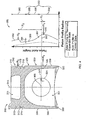
- FIG. 4 shows a cross-sectional view of the piston 300 in the thrust plane.
- the piston 300 may have some similar features to the previously described embodiments, but the piston 300 has a different axial profile 350.
- the piston may include a head portion 310, a skirt portion 320, a pin axis 305 and a piston axis 315.
- the head portion 310 may have a combustion bowl 311, a top surface 312, and ring grooves 313 and 314 that operate similar to the previously described embodiments.
- the skirt portion 320 may have a circumferential wall 326 that at least partially surrounds a hollow portion 321 proximal to the bottom 322 of the piston 300.
- the skirt portion 320 may include a major thrust side 330 and a minor thrust side 340 that may slidably engage the cylinder wall of an engine, similar to the previously described embodiments.
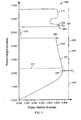
- the axial profile line 350 of the piston 300 may be represented on a plot showing the radius in the thrust plane relative to the axial height from the piston bottom 322.
- the plot in FIG. 4 illustrates the axial profile of the piston 300 at or about operating temperature (refer to the solid line) and at or about ambient room temperature (refer to the dashed line).
- the axial profile 350 of the piston 300 may be different depending on whether the piston 300 is at or about operating temperature or at or about ambient room temperature.
- the intermediate skirt profile 356 may be generally convex or linear when the piston is in a cooled state, but due to thermal expansion of the circumferential wall, the intermediate skirt profile 356 may adjust to include the concave curvature.
- the intermediate skirt profile 356 may include a concave curvature both when the piston 300 is in a thermally expanded state and when the piston 300 is in a cooled state.
- the piston skirt profile may include a lower skirt profile line 354, the intermediate skirt profile line 356, and an upper skirt profile line 358.
- at least a portion of the lower skirt profile line 354 may have a convex curvature including a maximum radius point 355.
- the lower skirt profile line 354 may include other curvatures or slopes.
- the lowest portion of the lower skirt profile line 354 may include substantially linear profile that represents a linear reduction in the piston radius from the maximum radius point 355 to the piston bottom 322.
- the lowest portion of the lower skirt profile line 154 may include no reduction in the piston radius from a location at or about the maximum radius point 355 to a location at or about the piston bottom 322.
- Such a configuration may cause a radial offset 364 between the upper skirt and the piston head, which may be used to focus the centroid of the thrust reaction forces on the piston skirt 320 (represented as force centroid R1) to an axial position at or slightly below the centerline 317 of the wrist pin (described in more detail below) in accordance with the invention.
- the axial profile line 350 of the piston 300 in a thermally expanded state may be configured so that the radial offset 364 reduces the thrust reaction forces upon the upper skirt portion 356 (e.g., some portion of the upper skirt may not even contact the cylinder wall) and focuses the thrust reaction forces so that a centroid (represented as force centroid R1) is located at or slightly below the centerline 317 of the wrist pin (e.g., located at an axial height at or below the pivot axis 305).
- a centroid represented as force centroid R1
- Such a configuration is capable of reducing the thrust force moment that would ordinarily cause a rocking motion of the piston 300.
- the radial offset 364 may substantially reduce or eliminate the contact between the cylinder wall and the upper skirt portion 358.
- the thrust load may be substantially distributed along two parts of the major thrust side 330-along the piston skirt 320 and along the piston head 310. These two parts may bear a different set of thrust reaction forces, which are represented as force centroid R1 and force centroid R2. Due to the axial profile shape of the skirt 320 and due to the radial offset 364 of the upper skirt portion, the force centroid R1 may occur at or slightly below the centerline 317 of the wrist pin (proximal to the maximum radius point 355).
- the thrust reaction forces can be expressed as a function of the thrust force which is transmitted through the pin centerline 317 (represented as force T in FIG. 4 ).
- X1 is the axial position of the centroid of the thrust reaction forces on the piston skirt 320 (represented as force controid R1) relative to the height of the wrist pin centerline 317
- X2 is the axial position of the centroid of the thrust reaction forces on the piston head 310 (represented as force centroid R2) relative to the height of the wrist pin centerline 317 (refer, for example, to FIG. 4 ).
- the centroid (R1) of the thrust reaction forces on the piston skirt 320 may occur at or slightly below the height of the wrist pin centerline 317 so that X1 is relatively small (e.g., X1 ⁇ X2).
- X1 is relatively small
- the centroid (R2) of the thrust reaction forces on the piston head 310 becomes relatively small (e.g., R2 ⁇ R1).
- crevice volume Combustion mixture received in the crevice volume is typically not fully combusted and is thus exhausted as unburned hydrocarbons.
- the reduced crevice volume reduces the amount of unburned combustion mixture exhausted as undesirable emissions, because the volume of unburned combustion mixture is smaller.
- the tighter clearance gap between the top land 316 and the cylinder wall and the lower magnitude of the thrust reaction forces on the piston head 310 may substantially reduce wear on the top land 316, the piston ring(s), and the cylinder wall.
- the axial profile of the piston skirt 320 may be configured so that the reaction force centroid (R1) is aligned at or slightly below the height of the wrist pin centerline 317.
- the radial offset 364 may be increased to further reduce the amount of upper skirt portion 358 that bears upon the cylinder wall, which may cause the reaction force centroid (R1) to be located at a lower axial position on the skirt 320.
- the lower skirt portion 354 may include the maximum radius 355 proximal to the height of the wrist pin center line 317 so that as the thrust load increases and deflect the piston skirt 320, the loaded area of the skirt 320 may increase but the centroid (R1) of the thrust reaction forces on the piston skirt 320 may remain at or slightly below the pin centerline 317. In such circumstances, the magnitude of centroid (R1) for the thrust reaction forces on the piston skirt 320 would not exceed the magnitude of the thrust force (T). (If the reaction force centroid (R1) migrated towards the upper portion of the piston skirt 320, the axial position (X1) would have a negative value, thus causing the magnitude of reaction force centroid (R1) to be greater than the magnitude of the thrust force (T).)
- the minor thrust side axial profile can, in some instances, be different than the major thrust side axial profile.
- the radius one side may be different from the radius of the other. Accordingly, other embodiments are within the scope of the following claims, which define the scope of the invention.
Landscapes
- Engineering & Computer Science (AREA)
- General Engineering & Computer Science (AREA)
- Chemical & Material Sciences (AREA)
- Combustion & Propulsion (AREA)
- Mechanical Engineering (AREA)
- Pistons, Piston Rings, And Cylinders (AREA)
Claims (13)
- Moteur à combustion interne comprenant :au moins une paroi (210) définissant un alésage (205) ; etun piston (300) disposé dans l'alésage (205) et couplé à une tige de piston (102) pour pivoter autour d'un axe de pivot (305), le piston comprenant une surface extérieure substantiellement circonférentielle comportant une partie tête (310) et une ligne de profil de jupe (320) sous la partie tête (310), dans lequel la partie tête (310) comprend des gorges de segment (314, 315), et dans lequel la ligne de profil de jupe (320) commence à et s'étend sous une paroi inférieure d'une gorge de segment la plus basse (314) du piston, au moins une partie de la surface extérieure portant contre la paroi (210) dans un plan de poussée quand le piston (300) est sensiblement à la température de fonctionnement et soumis à une force de poussée (T), caractérisé en ce que la partie de la force de poussée (T) supportée par la ligne de profil de jupe (320) dans le plan de poussée est représentée par un centroïde de forces de jupe (R1), le centroïde de forces de jupe (R1) étant positionné à une hauteur axiale située à ou sous l'axe de pivot (305),dans lequel la partie tête (310) de la surface extérieure a des rayons qui sont plus grands qu'au moins une partie des rayons de la ligne de profil de jupe (320) de la surface extérieure quand le piston est sensiblement à la température de fonctionnement.
- Moteur selon la revendication 1, dans lequel la partie de la force de poussée (T) supportée par la partie tête (310) est représentée par un centroïde de forces de tête (R2), le centroïde de forces de tête (R2) ayant une amplitude substantiellement plus petite que celle du centroïde de forces de jupe (R1).
- Moteur selon la revendication 2, dans lequel le centroïde de forces de tête (R2) est positionné à une hauteur axiale située au dessus de l'axe de pivot (305), le centroïde de forces de tête étant positionné à une distance substantiellement plus grande de l'axe de pivot (305) que le centroïde de forces de jupe (R1).
- Moteur selon la revendication 1, dans lequel la surface extérieure a un profil (350) dans le plan de poussée qui comprend une ligne de profil de jupe inférieure (354), une ligne de profil de jupe intermédiaire (356) et une ligne de profil de jupe supérieure (358), la ligne de profil de jupe intermédiaire (356) comportant une courbure concave dans le plan de poussée quand le piston (300) est sensiblement à la température de fonctionnement.
- Moteur selon la revendication 4, dans lequel le profil (350) dans le plan de poussée de la surface circonférentielle extérieure réalise la transition d'une courbure sensiblement convexe de la ligne de profil de jupe inférieure (354) dans le plan de poussée à la courbure sensiblement concave de la ligne de profil de jupe intermédiaire (356).
- Moteur selon la revendication 1, dans lequel la surface extérieure a un profil (350) dans le plan de poussée qui comprend une ligne de profil de jupe inférieure (354), une ligne de profil de jupe intermédiaire (356) et une ligne de profil de jupe supérieure (358), la surface extérieure ayant un décalage radial (364) dans le plan de poussée au dessus de l'axe de pivot (305) quand le piston (300) est sensiblement à la température de fonctionnement.
- Moteur selon la revendication 6, dans lequel la ligne de profil de jupe supérieure (358) comprend des rayons dans le plan de poussée qui sont plus petits qu'au moins une partie des rayons de la partie tête (310) quand le piston (300) est sensiblement à la température de fonctionnement.
- Moteur selon la revendication 1, dans lequel la surface extérieure a un profil (350) dans le plan de poussée qui comprend une ligne de profil de jupe inférieure (354), une ligne de profil de jupe intermédiaire (356) et une ligne de profil de jupe supérieure (358), la ligne de profil de jupe inférieure (354) ayant un rayon maximum qui est en ajustement avec serrage avec la paroi (210) quand le piston (300) est sensiblement à la température de fonctionnement.
- Moteur selon la revendication 8, dans lequel une partie de jupe inférieure définie par la ligne de profil de jupe inférieure (354) fléchit quand elle est en ajustement avec serrage pour éviter le grippage du piston (300) dans l'alésage (205).
- Moteur selon la revendication 8, dans lequel une partie de jupe inférieure définie par la ligne de profil de jupe inférieure (354) est élastique contre les grand et petit côtés de poussée (230 et 240) de la paroi (210) dans l'ajustement avec serrage avec la paroi (210).
- Moteur selon la revendication 10, dans lequel la surface extérieure est apte à guider le piston (300) dans l'alésage (205) quand la ligne de profil de jupe inférieure (354) est élastique contre les grand et petit côtés de poussée (230 et 240) de la paroi (210).
- Moteur selon la revendication 10, dans lequel, quand la ligne de profil de jupe inférieure (354) est élastique contre les grand et petit côtés de poussée (230 et 240) de la paroi (210), la ligne de profil de jupe supérieure (358) est décalée radialement du grand côté de poussée (230) de la paroi (210) dans le plan de poussée.
- Moteur selon la revendication 1, dans lequel le piston (300) comprend en outre un profil polaire (170) dans un plan radial et le profil polaire est asymétrique autour de l'axe de pivot (305).
Applications Claiming Priority (3)
| Application Number | Priority Date | Filing Date | Title |
|---|---|---|---|
| US11/265,948 US7293497B2 (en) | 2005-11-03 | 2005-11-03 | Piston |
| US11/265,870 US7302884B2 (en) | 2005-11-03 | 2005-11-03 | Piston |
| EP06844250.8A EP1943444B2 (fr) | 2005-11-03 | 2006-11-02 | Piston |
Related Parent Applications (3)
| Application Number | Title | Priority Date | Filing Date |
|---|---|---|---|
| EP06844250.8A Division-Into EP1943444B2 (fr) | 2005-11-03 | 2006-11-02 | Piston |
| EP06844250.8A Division EP1943444B2 (fr) | 2005-11-03 | 2006-11-02 | Piston |
| EP06844250.8 Division | 2006-11-02 |
Publications (2)
| Publication Number | Publication Date |
|---|---|
| EP2096337A1 EP2096337A1 (fr) | 2009-09-02 |
| EP2096337B1 true EP2096337B1 (fr) | 2011-08-10 |
Family
ID=37814063
Family Applications (2)
| Application Number | Title | Priority Date | Filing Date |
|---|---|---|---|
| EP09162350A Active EP2096337B1 (fr) | 2005-11-03 | 2006-11-02 | Piston |
| EP06844250.8A Active EP1943444B2 (fr) | 2005-11-03 | 2006-11-02 | Piston |
Family Applications After (1)
| Application Number | Title | Priority Date | Filing Date |
|---|---|---|---|
| EP06844250.8A Active EP1943444B2 (fr) | 2005-11-03 | 2006-11-02 | Piston |
Country Status (7)
| Country | Link |
|---|---|
| EP (2) | EP2096337B1 (fr) |
| AT (2) | ATE475826T1 (fr) |
| BR (1) | BRPI0618097B1 (fr) |
| CA (2) | CA2624119C (fr) |
| DE (1) | DE602006015834D1 (fr) |
| RU (1) | RU2419736C2 (fr) |
| WO (1) | WO2007056044A1 (fr) |
Cited By (1)
| Publication number | Priority date | Publication date | Assignee | Title |
|---|---|---|---|---|
| US9932930B2 (en) | 2014-01-14 | 2018-04-03 | General Electric Company | Piston with reduced top land height and tight top land piston profile |
Families Citing this family (3)
| Publication number | Priority date | Publication date | Assignee | Title |
|---|---|---|---|---|
| DE102009012161B8 (de) | 2009-03-06 | 2012-12-13 | Fraunhofer-Gesellschaft zur Förderung der angewandten Forschung e.V. | Verfahren zur Herstellung von Polysaccharidderivaten |
| DE102014010156A1 (de) | 2014-07-09 | 2015-07-09 | Daimler Ag | Anordnung eines Kolbens in einem Zylinder einer Hubkolben-Verbrennungskraftmaschine sowie Kolben für eine Hubkolben-Verbrennungskraftmaschine |
| US9359971B2 (en) | 2014-08-21 | 2016-06-07 | General Electric Company | System for controlling deposits on cylinder liner and piston of reciprocating engine |
Family Cites Families (10)
| Publication number | Priority date | Publication date | Assignee | Title |
|---|---|---|---|---|
| SU1249183A1 (ru) * | 1984-09-11 | 1986-08-07 | Производственное Объединение "Владимирский Тракторный Завод Им.А.А.Жданова" | Поршень дл двигател внутреннего сгорани |
| DE3437111A1 (de) † | 1984-10-10 | 1986-04-10 | Kolbenschmidt AG, 7107 Neckarsulm | Leichtmetallkolben |
| GB8432015D0 (en) † | 1984-12-19 | 1985-01-30 | Ae Plc | Pistons |
| DE3820473C2 (de) * | 1986-12-18 | 1998-03-26 | Mahle Gmbh | Leichter Tauchkolben für Verbrennungsmotoren |
| DE3740820C1 (en) | 1987-12-02 | 1989-01-19 | Mahle Gmbh | Trunk piston for internal combustion engines with an upper inelastic and a lower elastic shaft region |
| WO1990007642A1 (fr) * | 1988-12-24 | 1990-07-12 | Mahle Gmbh | Pisotn plongeur leger pour moteurs a combustion interne |
| JPH03110159U (fr) † | 1990-02-27 | 1991-11-12 | ||
| JP2697321B2 (ja) * | 1991-01-25 | 1998-01-14 | 日産自動車株式会社 | 内燃機関のピストン |
| JPH09170490A (ja) | 1995-12-19 | 1997-06-30 | Komatsu Ltd | 内燃機関用鋳鉄ピストン |
| US6502539B2 (en) † | 2001-06-01 | 2003-01-07 | Federal-Mogul World Wide, Inc. | Articulated piston having a profiled skirt |
-
2006
- 2006-11-02 EP EP09162350A patent/EP2096337B1/fr active Active
- 2006-11-02 AT AT06844250T patent/ATE475826T1/de active
- 2006-11-02 CA CA2624119A patent/CA2624119C/fr active Active
- 2006-11-02 AT AT09162350T patent/ATE519976T1/de active
- 2006-11-02 CA CA2840589A patent/CA2840589C/fr active Active
- 2006-11-02 WO PCT/US2006/042774 patent/WO2007056044A1/fr not_active Ceased
- 2006-11-02 EP EP06844250.8A patent/EP1943444B2/fr active Active
- 2006-11-02 DE DE602006015834T patent/DE602006015834D1/de active Active
- 2006-11-02 BR BRPI0618097-3A patent/BRPI0618097B1/pt active IP Right Grant
- 2006-11-02 RU RU2008122043/06A patent/RU2419736C2/ru active
Cited By (1)
| Publication number | Priority date | Publication date | Assignee | Title |
|---|---|---|---|---|
| US9932930B2 (en) | 2014-01-14 | 2018-04-03 | General Electric Company | Piston with reduced top land height and tight top land piston profile |
Also Published As
| Publication number | Publication date |
|---|---|
| RU2419736C2 (ru) | 2011-05-27 |
| RU2008122043A (ru) | 2009-12-10 |
| DE602006015834D1 (de) | 2010-09-09 |
| EP1943444B2 (fr) | 2019-07-17 |
| ATE519976T1 (de) | 2011-08-15 |
| CA2624119C (fr) | 2015-02-17 |
| BRPI0618097A2 (pt) | 2011-08-16 |
| CA2624119A1 (fr) | 2007-05-18 |
| WO2007056044A1 (fr) | 2007-05-18 |
| CA2840589A1 (fr) | 2007-05-18 |
| EP2096337A1 (fr) | 2009-09-02 |
| CA2840589C (fr) | 2016-02-02 |
| BRPI0618097B1 (pt) | 2021-01-26 |
| ATE475826T1 (de) | 2010-08-15 |
| EP1943444A1 (fr) | 2008-07-16 |
| EP1943444B1 (fr) | 2010-07-28 |
Similar Documents
| Publication | Publication Date | Title |
|---|---|---|
| US7506575B2 (en) | Piston | |
| US7493850B2 (en) | Piston | |
| US6357341B1 (en) | Piston of internal combustion engine | |
| EP2045488B1 (fr) | Segment de piston de moteur réciproque | |
| US11536222B2 (en) | Block ribs for reducing liner distortion | |
| US8286607B2 (en) | Wrist pin, connecting rod, piston and piston assembly therewith and methods of constructing and assembling the same | |
| US5695199A (en) | Piston sealing assembly | |
| EP2096337B1 (fr) | Piston | |
| US7938058B2 (en) | Engine piston with rolling element skirt | |
| EP1448918B1 (fr) | Piston pour moteur a combustion interne | |
| JP4889975B2 (ja) | ピストン装置 | |
| EP4379204A1 (fr) | Piston pour assemblage avec un cylindre | |
| Donahue | Piston | |
| JP2005188303A (ja) | エンジンのピストン構造 | |
| JP6166950B2 (ja) | 内燃機関の軸受構造 | |
| JPH0447148A (ja) | 往復動機械 |
Legal Events
| Date | Code | Title | Description |
|---|---|---|---|
| PUAI | Public reference made under article 153(3) epc to a published international application that has entered the european phase |
Free format text: ORIGINAL CODE: 0009012 |
|
| AC | Divisional application: reference to earlier application |
Ref document number: 1943444 Country of ref document: EP Kind code of ref document: P |
|
| AK | Designated contracting states |
Kind code of ref document: A1 Designated state(s): AT BE BG CH CY CZ DE DK EE ES FI FR GB GR HU IE IS IT LI LT LU LV MC NL PL PT RO SE SI SK TR |
|
| 17P | Request for examination filed |
Effective date: 20091023 |
|
| 17Q | First examination report despatched |
Effective date: 20100628 |
|
| GRAP | Despatch of communication of intention to grant a patent |
Free format text: ORIGINAL CODE: EPIDOSNIGR1 |
|
| GRAS | Grant fee paid |
Free format text: ORIGINAL CODE: EPIDOSNIGR3 |
|
| GRAA | (expected) grant |
Free format text: ORIGINAL CODE: 0009210 |
|
| AC | Divisional application: reference to earlier application |
Ref document number: 1943444 Country of ref document: EP Kind code of ref document: P |
|
| AK | Designated contracting states |
Kind code of ref document: B1 Designated state(s): AT BE BG CH CY CZ DE DK EE ES FI FR GB GR HU IE IS IT LI LT LU LV MC NL PL PT RO SE SI SK TR |
|
| REG | Reference to a national code |
Ref country code: GB Ref legal event code: FG4D |
|
| REG | Reference to a national code |
Ref country code: CH Ref legal event code: EP |
|
| REG | Reference to a national code |
Ref country code: IE Ref legal event code: FG4D |
|
| REG | Reference to a national code |
Ref country code: DE Ref legal event code: R096 Ref document number: 602006023776 Country of ref document: DE Effective date: 20111020 |
|
| REG | Reference to a national code |
Ref country code: ES Ref legal event code: FG2A Ref document number: 2367951 Country of ref document: ES Kind code of ref document: T3 Effective date: 20111111 |
|
| REG | Reference to a national code |
Ref country code: NL Ref legal event code: T3 |
|
| LTIE | Lt: invalidation of european patent or patent extension |
Effective date: 20110810 |
|
| PG25 | Lapsed in a contracting state [announced via postgrant information from national office to epo] |
Ref country code: SE Free format text: LAPSE BECAUSE OF FAILURE TO SUBMIT A TRANSLATION OF THE DESCRIPTION OR TO PAY THE FEE WITHIN THE PRESCRIBED TIME-LIMIT Effective date: 20110810 Ref country code: PT Free format text: LAPSE BECAUSE OF FAILURE TO SUBMIT A TRANSLATION OF THE DESCRIPTION OR TO PAY THE FEE WITHIN THE PRESCRIBED TIME-LIMIT Effective date: 20111212 Ref country code: IS Free format text: LAPSE BECAUSE OF FAILURE TO SUBMIT A TRANSLATION OF THE DESCRIPTION OR TO PAY THE FEE WITHIN THE PRESCRIBED TIME-LIMIT Effective date: 20111210 Ref country code: LT Free format text: LAPSE BECAUSE OF FAILURE TO SUBMIT A TRANSLATION OF THE DESCRIPTION OR TO PAY THE FEE WITHIN THE PRESCRIBED TIME-LIMIT Effective date: 20110810 |
|
| PG25 | Lapsed in a contracting state [announced via postgrant information from national office to epo] |
Ref country code: LV Free format text: LAPSE BECAUSE OF FAILURE TO SUBMIT A TRANSLATION OF THE DESCRIPTION OR TO PAY THE FEE WITHIN THE PRESCRIBED TIME-LIMIT Effective date: 20110810 Ref country code: SI Free format text: LAPSE BECAUSE OF FAILURE TO SUBMIT A TRANSLATION OF THE DESCRIPTION OR TO PAY THE FEE WITHIN THE PRESCRIBED TIME-LIMIT Effective date: 20110810 Ref country code: CY Free format text: LAPSE BECAUSE OF FAILURE TO SUBMIT A TRANSLATION OF THE DESCRIPTION OR TO PAY THE FEE WITHIN THE PRESCRIBED TIME-LIMIT Effective date: 20110810 Ref country code: PL Free format text: LAPSE BECAUSE OF FAILURE TO SUBMIT A TRANSLATION OF THE DESCRIPTION OR TO PAY THE FEE WITHIN THE PRESCRIBED TIME-LIMIT Effective date: 20110810 Ref country code: GR Free format text: LAPSE BECAUSE OF FAILURE TO SUBMIT A TRANSLATION OF THE DESCRIPTION OR TO PAY THE FEE WITHIN THE PRESCRIBED TIME-LIMIT Effective date: 20111111 |
|
| PG25 | Lapsed in a contracting state [announced via postgrant information from national office to epo] |
Ref country code: BE Free format text: LAPSE BECAUSE OF FAILURE TO SUBMIT A TRANSLATION OF THE DESCRIPTION OR TO PAY THE FEE WITHIN THE PRESCRIBED TIME-LIMIT Effective date: 20110810 |
|
| PG25 | Lapsed in a contracting state [announced via postgrant information from national office to epo] |
Ref country code: SK Free format text: LAPSE BECAUSE OF FAILURE TO SUBMIT A TRANSLATION OF THE DESCRIPTION OR TO PAY THE FEE WITHIN THE PRESCRIBED TIME-LIMIT Effective date: 20110810 Ref country code: CZ Free format text: LAPSE BECAUSE OF FAILURE TO SUBMIT A TRANSLATION OF THE DESCRIPTION OR TO PAY THE FEE WITHIN THE PRESCRIBED TIME-LIMIT Effective date: 20110810 |
|
| PG25 | Lapsed in a contracting state [announced via postgrant information from national office to epo] |
Ref country code: EE Free format text: LAPSE BECAUSE OF FAILURE TO SUBMIT A TRANSLATION OF THE DESCRIPTION OR TO PAY THE FEE WITHIN THE PRESCRIBED TIME-LIMIT Effective date: 20110810 Ref country code: RO Free format text: LAPSE BECAUSE OF FAILURE TO SUBMIT A TRANSLATION OF THE DESCRIPTION OR TO PAY THE FEE WITHIN THE PRESCRIBED TIME-LIMIT Effective date: 20110810 |
|
| PLBE | No opposition filed within time limit |
Free format text: ORIGINAL CODE: 0009261 |
|
| STAA | Information on the status of an ep patent application or granted ep patent |
Free format text: STATUS: NO OPPOSITION FILED WITHIN TIME LIMIT |
|
| PG25 | Lapsed in a contracting state [announced via postgrant information from national office to epo] |
Ref country code: MC Free format text: LAPSE BECAUSE OF NON-PAYMENT OF DUE FEES Effective date: 20111130 Ref country code: DK Free format text: LAPSE BECAUSE OF FAILURE TO SUBMIT A TRANSLATION OF THE DESCRIPTION OR TO PAY THE FEE WITHIN THE PRESCRIBED TIME-LIMIT Effective date: 20110810 |
|
| REG | Reference to a national code |
Ref country code: CH Ref legal event code: PL |
|
| 26N | No opposition filed |
Effective date: 20120511 |
|
| GBPC | Gb: european patent ceased through non-payment of renewal fee |
Effective date: 20111110 |
|
| PG25 | Lapsed in a contracting state [announced via postgrant information from national office to epo] |
Ref country code: CH Free format text: LAPSE BECAUSE OF NON-PAYMENT OF DUE FEES Effective date: 20111130 Ref country code: LI Free format text: LAPSE BECAUSE OF NON-PAYMENT OF DUE FEES Effective date: 20111130 |
|
| REG | Reference to a national code |
Ref country code: FR Ref legal event code: ST Effective date: 20120731 |
|
| REG | Reference to a national code |
Ref country code: IE Ref legal event code: MM4A |
|
| REG | Reference to a national code |
Ref country code: DE Ref legal event code: R097 Ref document number: 602006023776 Country of ref document: DE Effective date: 20120511 |
|
| PG25 | Lapsed in a contracting state [announced via postgrant information from national office to epo] |
Ref country code: GB Free format text: LAPSE BECAUSE OF NON-PAYMENT OF DUE FEES Effective date: 20111110 Ref country code: IE Free format text: LAPSE BECAUSE OF NON-PAYMENT OF DUE FEES Effective date: 20111102 |
|
| PG25 | Lapsed in a contracting state [announced via postgrant information from national office to epo] |
Ref country code: FR Free format text: LAPSE BECAUSE OF NON-PAYMENT OF DUE FEES Effective date: 20111130 |
|
| PG25 | Lapsed in a contracting state [announced via postgrant information from national office to epo] |
Ref country code: LU Free format text: LAPSE BECAUSE OF NON-PAYMENT OF DUE FEES Effective date: 20111102 |
|
| PG25 | Lapsed in a contracting state [announced via postgrant information from national office to epo] |
Ref country code: BG Free format text: LAPSE BECAUSE OF FAILURE TO SUBMIT A TRANSLATION OF THE DESCRIPTION OR TO PAY THE FEE WITHIN THE PRESCRIBED TIME-LIMIT Effective date: 20111110 |
|
| PG25 | Lapsed in a contracting state [announced via postgrant information from national office to epo] |
Ref country code: TR Free format text: LAPSE BECAUSE OF FAILURE TO SUBMIT A TRANSLATION OF THE DESCRIPTION OR TO PAY THE FEE WITHIN THE PRESCRIBED TIME-LIMIT Effective date: 20110810 |
|
| PG25 | Lapsed in a contracting state [announced via postgrant information from national office to epo] |
Ref country code: HU Free format text: LAPSE BECAUSE OF FAILURE TO SUBMIT A TRANSLATION OF THE DESCRIPTION OR TO PAY THE FEE WITHIN THE PRESCRIBED TIME-LIMIT Effective date: 20110810 |
|
| PGFP | Annual fee paid to national office [announced via postgrant information from national office to epo] |
Ref country code: AT Payment date: 20151021 Year of fee payment: 10 |
|
| REG | Reference to a national code |
Ref country code: AT Ref legal event code: MM01 Ref document number: 519976 Country of ref document: AT Kind code of ref document: T Effective date: 20161102 |
|
| PG25 | Lapsed in a contracting state [announced via postgrant information from national office to epo] |
Ref country code: AT Free format text: LAPSE BECAUSE OF NON-PAYMENT OF DUE FEES Effective date: 20161102 |
|
| REG | Reference to a national code |
Ref country code: ES Ref legal event code: PC2A Owner name: GE DISTRIBUTED POWER, INC Effective date: 20181106 |
|
| REG | Reference to a national code |
Ref country code: DE Ref legal event code: R082 Ref document number: 602006023776 Country of ref document: DE Representative=s name: RUEGER ABEL PATENTANWAELTE PARTGMBB, DE Ref country code: DE Ref legal event code: R082 Ref document number: 602006023776 Country of ref document: DE Representative=s name: RUEGER ABEL PATENT- UND RECHTSANWAELTE, DE |
|
| REG | Reference to a national code |
Ref country code: DE Ref legal event code: R082 Ref document number: 602006023776 Country of ref document: DE Representative=s name: RUEGER ABEL PATENTANWAELTE PARTGMBB, DE Ref country code: DE Ref legal event code: R082 Ref document number: 602006023776 Country of ref document: DE Representative=s name: RUEGER ABEL PATENT- UND RECHTSANWAELTE, DE Ref country code: DE Ref legal event code: R081 Ref document number: 602006023776 Country of ref document: DE Owner name: GE DISTRIBUTED POWER, INC., WAUKESHA, US Free format text: FORMER OWNER: DRESSER, INC., ADDISON, TEX., US |
|
| REG | Reference to a national code |
Ref country code: NL Ref legal event code: PD Owner name: GE DISTRIBUTED POWER, INC.; US Free format text: DETAILS ASSIGNMENT: CHANGE OF OWNER(S), CHANGE OF LEGAL ENTITY; FORMER OWNER NAME: DRESSER, LLC Effective date: 20181101 |
|
| PGFP | Annual fee paid to national office [announced via postgrant information from national office to epo] |
Ref country code: NL Payment date: 20251022 Year of fee payment: 20 |
|
| PGFP | Annual fee paid to national office [announced via postgrant information from national office to epo] |
Ref country code: DE Payment date: 20251022 Year of fee payment: 20 |
|
| PGFP | Annual fee paid to national office [announced via postgrant information from national office to epo] |
Ref country code: FI Payment date: 20251022 Year of fee payment: 20 Ref country code: IT Payment date: 20251022 Year of fee payment: 20 |
|
| PGFP | Annual fee paid to national office [announced via postgrant information from national office to epo] |
Ref country code: ES Payment date: 20251201 Year of fee payment: 20 |