EP2096338A1 - Bouchon, panneau à structure double couche, et contenant de réfrigération - Google Patents
Bouchon, panneau à structure double couche, et contenant de réfrigération Download PDFInfo
- Publication number
- EP2096338A1 EP2096338A1 EP07830938A EP07830938A EP2096338A1 EP 2096338 A1 EP2096338 A1 EP 2096338A1 EP 07830938 A EP07830938 A EP 07830938A EP 07830938 A EP07830938 A EP 07830938A EP 2096338 A1 EP2096338 A1 EP 2096338A1
- Authority
- EP
- European Patent Office
- Prior art keywords
- panel
- internally
- cap
- threaded member
- subportion
- Prior art date
- Legal status (The legal status is an assumption and is not a legal conclusion. Google has not performed a legal analysis and makes no representation as to the accuracy of the status listed.)
- Withdrawn
Links
- 239000000463 material Substances 0.000 claims abstract description 22
- 239000011229 interlayer Substances 0.000 claims abstract description 21
- 239000012530 fluid Substances 0.000 claims abstract description 20
- 238000007789 sealing Methods 0.000 claims abstract description 9
- 230000002093 peripheral effect Effects 0.000 claims abstract description 4
- 239000013013 elastic material Substances 0.000 claims description 8
- 238000000034 method Methods 0.000 claims description 5
- 238000005187 foaming Methods 0.000 claims description 2
- 230000001939 inductive effect Effects 0.000 claims description 2
- 239000011810 insulating material Substances 0.000 description 15
- 230000005489 elastic deformation Effects 0.000 description 5
- 239000006261 foam material Substances 0.000 description 4
- 238000004519 manufacturing process Methods 0.000 description 3
- 238000004806 packaging method and process Methods 0.000 description 3
- 230000007423 decrease Effects 0.000 description 2
- 230000001965 increasing effect Effects 0.000 description 2
- 239000011347 resin Substances 0.000 description 2
- 229920005989 resin Polymers 0.000 description 2
- JOYRKODLDBILNP-UHFFFAOYSA-N Ethyl urethane Chemical compound CCOC(N)=O JOYRKODLDBILNP-UHFFFAOYSA-N 0.000 description 1
- XAGFODPZIPBFFR-UHFFFAOYSA-N aluminium Chemical compound [Al] XAGFODPZIPBFFR-UHFFFAOYSA-N 0.000 description 1
- 229910052782 aluminium Inorganic materials 0.000 description 1
- PNEYBMLMFCGWSK-UHFFFAOYSA-N aluminium oxide Inorganic materials [O-2].[O-2].[O-2].[Al+3].[Al+3] PNEYBMLMFCGWSK-UHFFFAOYSA-N 0.000 description 1
- 238000001816 cooling Methods 0.000 description 1
- 238000002788 crimping Methods 0.000 description 1
- 239000006260 foam Substances 0.000 description 1
- 239000007788 liquid Substances 0.000 description 1
- 238000012986 modification Methods 0.000 description 1
- 230000004048 modification Effects 0.000 description 1
- 238000003825 pressing Methods 0.000 description 1
- 239000003507 refrigerant Substances 0.000 description 1
- 230000000717 retained effect Effects 0.000 description 1
Images


Classifications
-
- F—MECHANICAL ENGINEERING; LIGHTING; HEATING; WEAPONS; BLASTING
- F25—REFRIGERATION OR COOLING; COMBINED HEATING AND REFRIGERATION SYSTEMS; HEAT PUMP SYSTEMS; MANUFACTURE OR STORAGE OF ICE; LIQUEFACTION SOLIDIFICATION OF GASES
- F25D—REFRIGERATORS; COLD ROOMS; ICE-BOXES; COOLING OR FREEZING APPARATUS NOT OTHERWISE PROVIDED FOR
- F25D23/00—General constructional features
- F25D23/06—Walls
- F25D23/065—Details
- F25D23/067—Supporting elements
-
- B—PERFORMING OPERATIONS; TRANSPORTING
- B29—WORKING OF PLASTICS; WORKING OF SUBSTANCES IN A PLASTIC STATE IN GENERAL
- B29C—SHAPING OR JOINING OF PLASTICS; SHAPING OF MATERIAL IN A PLASTIC STATE, NOT OTHERWISE PROVIDED FOR; AFTER-TREATMENT OF THE SHAPED PRODUCTS, e.g. REPAIRING
- B29C44/00—Shaping by internal pressure generated in the material, e.g. swelling or foaming ; Producing porous or cellular expanded plastics articles
- B29C44/02—Shaping by internal pressure generated in the material, e.g. swelling or foaming ; Producing porous or cellular expanded plastics articles for articles of definite length, i.e. discrete articles
- B29C44/12—Incorporating or moulding on preformed parts, e.g. inserts or reinforcements
- B29C44/1261—Avoiding impregnation of a preformed part
-
- F—MECHANICAL ENGINEERING; LIGHTING; HEATING; WEAPONS; BLASTING
- F16—ENGINEERING ELEMENTS AND UNITS; GENERAL MEASURES FOR PRODUCING AND MAINTAINING EFFECTIVE FUNCTIONING OF MACHINES OR INSTALLATIONS; THERMAL INSULATION IN GENERAL
- F16B—DEVICES FOR FASTENING OR SECURING CONSTRUCTIONAL ELEMENTS OR MACHINE PARTS TOGETHER, e.g. NAILS, BOLTS, CIRCLIPS, CLAMPS, CLIPS OR WEDGES; JOINTS OR JOINTING
- F16B37/00—Nuts or like thread-engaging members
- F16B37/12—Nuts or like thread-engaging members with thread-engaging surfaces formed by inserted coil-springs, discs, or the like; Independent pieces of wound wire used as nuts; Threaded inserts for holes
- F16B37/122—Threaded inserts, e.g. "rampa bolts"
-
- B—PERFORMING OPERATIONS; TRANSPORTING
- B29—WORKING OF PLASTICS; WORKING OF SUBSTANCES IN A PLASTIC STATE IN GENERAL
- B29C—SHAPING OR JOINING OF PLASTICS; SHAPING OF MATERIAL IN A PLASTIC STATE, NOT OTHERWISE PROVIDED FOR; AFTER-TREATMENT OF THE SHAPED PRODUCTS, e.g. REPAIRING
- B29C44/00—Shaping by internal pressure generated in the material, e.g. swelling or foaming ; Producing porous or cellular expanded plastics articles
- B29C44/02—Shaping by internal pressure generated in the material, e.g. swelling or foaming ; Producing porous or cellular expanded plastics articles for articles of definite length, i.e. discrete articles
- B29C44/12—Incorporating or moulding on preformed parts, e.g. inserts or reinforcements
- B29C44/14—Incorporating or moulding on preformed parts, e.g. inserts or reinforcements the preformed part being a lining
-
- F—MECHANICAL ENGINEERING; LIGHTING; HEATING; WEAPONS; BLASTING
- F25—REFRIGERATION OR COOLING; COMBINED HEATING AND REFRIGERATION SYSTEMS; HEAT PUMP SYSTEMS; MANUFACTURE OR STORAGE OF ICE; LIQUEFACTION SOLIDIFICATION OF GASES
- F25D—REFRIGERATORS; COLD ROOMS; ICE-BOXES; COOLING OR FREEZING APPARATUS NOT OTHERWISE PROVIDED FOR
- F25D2201/00—Insulation
- F25D2201/10—Insulation with respect to heat
- F25D2201/12—Insulation with respect to heat using an insulating packing material
- F25D2201/126—Insulation with respect to heat using an insulating packing material of cellular type
-
- Y—GENERAL TAGGING OF NEW TECHNOLOGICAL DEVELOPMENTS; GENERAL TAGGING OF CROSS-SECTIONAL TECHNOLOGIES SPANNING OVER SEVERAL SECTIONS OF THE IPC; TECHNICAL SUBJECTS COVERED BY FORMER USPC CROSS-REFERENCE ART COLLECTIONS [XRACs] AND DIGESTS
- Y10—TECHNICAL SUBJECTS COVERED BY FORMER USPC
- Y10T—TECHNICAL SUBJECTS COVERED BY FORMER US CLASSIFICATION
- Y10T29/00—Metal working
- Y10T29/49—Method of mechanical manufacture
- Y10T29/49826—Assembling or joining
-
- Y—GENERAL TAGGING OF NEW TECHNOLOGICAL DEVELOPMENTS; GENERAL TAGGING OF CROSS-SECTIONAL TECHNOLOGIES SPANNING OVER SEVERAL SECTIONS OF THE IPC; TECHNICAL SUBJECTS COVERED BY FORMER USPC CROSS-REFERENCE ART COLLECTIONS [XRACs] AND DIGESTS
- Y10—TECHNICAL SUBJECTS COVERED BY FORMER USPC
- Y10T—TECHNICAL SUBJECTS COVERED BY FORMER US CLASSIFICATION
- Y10T428/00—Stock material or miscellaneous articles
- Y10T428/24—Structurally defined web or sheet [e.g., overall dimension, etc.]
- Y10T428/24273—Structurally defined web or sheet [e.g., overall dimension, etc.] including aperture
- Y10T428/24322—Composite web or sheet
Definitions
- the present invention relates to a cap, a multi-layered panel, and a refrigerated container.
- a casing panel of the refrigerated container comprises an outer panel made of aluminum, an inner panel made of resin, and foam material as a thermal insulating material filled between the two panels.
- a nut is fixed to the outer panel to allow a fan, a frame or the like to be fastened and fixed thereto.
- this nut is a crimp nut.
- a through-hole is formed in the outer panel in advance, and the nut is fitted into and crimpedly fixed to the through-hole.
- the gap-sealing operation using a packaging tape requires a lot of time and effort, due to a need for attaching the packaging tape so as not to leave any gap. Particularly, in cases where it is necessary to perform the gap-sealing operation in dozens of positions per panel, it takes much more time and effort. Moreover, a gap is likely to be left even after the gap-sealing operation.
- a cap for attachment onto an internally-threaded member fixed to a through-hole of a panel which sandwiches an interlayer material in a fluid state or in a solidified state transformed therefrom, in cooperation with a counterpart of the panel.
- the cap comprises a bottomed tubular-shaped body portion adapted, upon the attachment onto the internally-threaded member, to be brought into close contact with an outer peripheral surface of the internally-threaded member while sealing a threaded hole of the internally-threaded member, and a panel-contact contributing portion supported by the body portion, and adapted, upon the attachment onto the internally-threaded member, to be at least partly brought into close contact with the panel.
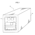
- FIG. 1 shows one embodiment of a refrigerated container according to the present invention.
- a refrigerated container 10 according to this embodiment comprises a rectangular parallelepiped-shaped casing 12, wherein a panel arranged at one longitudinal end of the casing 12 is a multi-layered panel as one embodiment of the present invention.
- the multi-layered panel 14 comprises an outer panel 16 constituting an outer wall of the casing 12, an inner panel 17 constituting an inner wall of the casing 12, and a thermal insulating material 18 as an interlayer material provided between these panels 16, 17.
- the outer panel 16 is made of alumina
- the inner panel 17 is made of resin.
- the thermal insulating material 18 is formed, for example, of a urethane foam material, and has been foamed during production of the panel. Thus, in a situation where the refrigerated container 10 is actually used, the insulating material 10 is already in a solidified state.
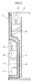
- the refrigerated container 10 is equipped with a refrigerating unit for cooling an internal space thereof.
- the refrigerating unit includes, as primary component devices, a compressor 21, a condenser 22, an evaporator 23, a condenser fan 24, and an evaporator fan 25.
- the compressor 21, the condenser 22, and the condenser fan 24 are arranged outside the casing 12, and the evaporator 23 and the evaporator fan 25 are arranged inside the casing 12.
- An internally-threaded member 30 (see FIG. 4 ) is fixed to the outer panel 16 of the multi-layered panel 14, and an externally-threaded member (not shown) is screwed with the internally-threaded member 30.
- the externally-threaded member is used for fixing a component device of the refrigerating unit or other component.
- an appropriate component as this component device includes the compressor 21, the condenser 22, the condenser fan 24, and a pipe (not shown) constituting a refrigerant circuit.
- the internally-threaded member 30 is fixed to the outer panel 16 while being inserted into each of a large number of through-holes 16a of the outer panel 16.
- the internally-threaded member 30 is a member having an internal thread 31 integrally formed thereon, and composed, for example, of a crimp nut.
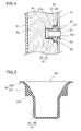
- the internally-threaded members 30 in the respective through-holes do not necessarily have the same size, but the size of each of the internally-threaded members 30 may be appropriately selected depending on a target object to be retained. All the internally-threaded members 30 have the same structure. Thus, one of the internally-threaded members 30 will be representatively described in detail with reference to FIG. 4 which shows a sectional view taken along the line IV-IV in FIG. 3 .
- the internally-threaded member 30 illustrated in FIG. 4 is one used for fixing the condenser 22.
- the internally-threaded member 30 has a tubular portion 32 formed in a tubular shape to have an internal thread 31 on an inner surface thereof, and a flange portion 33 provided at an end of the tubular portion 32.
- the inner surface of the tubular portion 32 is formed as a threaded hole.
- the internally-threaded member 30 is inserted into the through-hole 16a of the outer panel 16 in such a manner that the flange portion 33 is located on an outward side, i.e., on an opposite side of the thermal insulating material 18 with respect to the outer panel 16.
- the internally-threaded member 30 has a clamping portion 35 in an intermediate region of the tubular portion 32.
- the clamping portion 35 is provided as a means for clamping the outer panel 16 in cooperation with the flange portion 33 so as to fix the internally-threaded member 30 to the outer panel 16.
- the clamping portion 35 is formed through plastic deformation caused by axially compressing the tubular portion 32. In this manner, the internally-threaded member 30 is crimpedly fixed to the outer panel 16.
- a bolt (not shown) can be screwed with the internal thread 31 of the internally-threaded member 30 to retain the condenser 22 or the like.
- a cap 40 is attached onto the internally-threaded member 30.
- the cap 40 is used for preventing the thermal insulating material 18 in a fluid state from flowing into an inner side of the internal thread 31. Further, the cap 40 prevents the thermal insulating material 18 from leaking through a gap between the internally-threaded member 30 and a peripheral edge of the through-hole 16a of the outer panel 16.
- the cap 40 is disposed in a space between the outer panel 16 and the inner panel 17 to divide the space into a sub-space filled with the thermal insulating material 18 and a sub-space free of the existence of the thermal insulating material 18.
- the cap 40 is a single-piece product made of rubber. That is, the cap 40 is made of an elastic material. As also shown in FIG. 5 , the cap 40 comprises a bottomed tubular-shaped body portion 41, and a panel-contact contributing portion 42 supported by the body portion 41.
- the body portion 41 includes a bottom subportion 43, and a trunk subportion 44 continuous with an outer periphery of the bottom subportion 43.
- the trunk subportion 44 has an inner diameter slightly less than an outer diameter of the tubular portion 32 of the internally-threaded member 30. This allows the cap 40 to be brought into close contact with the trunk subportion 32 when it is attached onto the internally-threaded member 30. Further, based on a frictional resistance generated between the trunk subportion 44 and the tubular portion 32, the cap 40 becomes free from detachment from the internally-threaded member 30.
- the panel-contact contributing portion 42 is a region extending from the trunk subportion 44 of the body portion 44, while gradually increasing an inner diameter thereof.
- the panel-contact contributing portion 42 has a thick-walled subportion 47 and a distal end subportion 48.
- the panel-contact contributing portion 42 is adapted, upon the attachment onto the internally-threaded member 30, to be free from contact with the clamping portion 35. This allows the distal end subportion 48 to reliably become free from hindrance of close contact with the outer panel 16 upon the attachment.
- the panel-contact contributing portion 42 may be brought into contact with the clamping portion 35 to an extent that the close contact between the distal end subportion 48 and the outer panel 16 is not hindered.
- the thick-walled subportion 47 is a region formed in continuous relation to the trunk subportion 44 to protrude radially outwardly from the trunk subportion 44 so as to have a wall thickness greater than those of the trunk subportion 44 and the distal end subportion 48.
- the thick-walled subportion 47 is formed in a circular ring shape which has a generally triangular shape in vertical section, and has a receiving surface 47a extending in a direction approximately perpendicular to the trunk subportion 44.
- the receiving surface 47a is formed to receive a pushing force applied thereto from the side of the trunk subportion 44 by a jig (not shown), and comprised of an end surface of the thick-walled portion 47 on the side of the trunk subportion 44.
- the thick-walled portion 47 may be configured such that the direction thereof is slightly changed in response to an elastic deformation of the distal end subportion 48, or may be configured such that the direction thereof is not changed at all even if the distal end subportion 48 is elastically deformed. That is, the configuration may satisfy a condition that the receiving surface 47a intersects with the trunk subportion 44 approximately at a right angle so as to intersect with a direction of the attachment approximately at a right angle at least upon the attachment onto the internally-threaded member 30.
- the receiving surface 47a of the thick-walled subportion 47 can be utilized. Specifically, the receiving surface 47a can be pushed by the tubular-shaped jig to pull the trunk subportion 44 under a condition that the thick-walled subportion 47 having rigidity maintains its shape. This makes it possible to fit the cap 40 all the way while suppressing large deformation of the panel-contact contributing portion 42 itself.
- the distal end subportion 48 is a region continuous with a distal edge of the thick-walled subportion 47.
- the distal end subportion 48 is formed in a circular ring shape having a thickness which gradually decreases in a direction from the thick-walled subportion 47 to a distal edge thereof. Further, the distal end subportion 48 is formed in a flared shape having a diameter which gradually increases toward the distal edge thereof.
- the distal end subportion 48 is adapted, upon the attachment onto the cap 40, to be brought into contact with the outer panel 16 and elastically deformed in such a manner that the distal edge thereof is increased in diameter. This makes it possible to allow the distal end subportion 48 to be brought into surface contact with the outer panel 16 through an inner surface thereof, so as to effectively bring out sealability.
- the distal end subportion 48 located on the side of an distal edge of the cap relative to the thick-walled subportion 47 mainly undergoes elastic deformation, whereas the panel-contact contributing portion 42 itself has small elastic deformation, if any.
- a type having a length greater than a protruding distance of the internally-threaded member 30 from the outer panel 16 is selected as the cap 40.
- the length is set such that, when the cap 40 is attached onto the internally-threaded member 30, a gap is defined between the bottom subportion 43 of the cap 40 and an inner edge of the internally-threaded member 30 without contact therebetween.
- the cap 40 can be attached onto the internally-threaded member 30 in such a manner as to leave a gap between the internally-threaded member 30 and the bottom subportion 43 of the cap 40, without being affected by a variation in the protruding distance during a crimping operation, and a thickness of the outer panel 16. This makes it possible to ensure close contact between the outer panel 16 and the distal end subportion 48 of the cap 40.
- a large number of through-holes 16a are formed in the outer panel 16 at given positions, and the internally-threaded member 30 is inserted into each of the through-holes 16a.
- each of the internally-threaded members 30 is inserted from the side of an outer surface of the outer panel 16.
- the flange portion 33 is positioned on the side of the outer surface of the outer panel 16.
- each of the internally-threaded members 30 is crimped to the outer panel 16 using a given jig. Subsequently, the cap 40 is attached to each of the internally-threaded members 30.
- the cap 40 is attached onto a portion of the internally-threaded member 30 protruding on the side of an inner surface of the outer panel 14, i.e., attached from the side of the inner surface of the outer panel 16 (from the side of a surface of the outer panel 16 opposed to the inner panel 17).
- the receiving surface 47a of the thick-walled subportion 47 is pushed using a given jig to cap the body portion 41 onto the tubular portion 32 of the internally-threaded member 30.
- the trunk subportion 44 of the cap 40 can be fitted onto the tubular portion 32 while being expanded radially outwardly by the internally-threaded member 30, to ensure close contact between the trunk subportion 44 of the cap 40 and the tubular portion 32 of the internally-threaded member 30.
- the receiving surface 47a extending in a direction approximately perpendicular to a direction of the attachment onto the internally-threaded member 30 can be pushed.
- the inner panel 17 is assembled to the outer panel 16.
- the two panels 16, 17 are assembled together to allow the cap 40 to be located between the two panels 16, 17.
- a pre-foam thermal insulating material 18 in liquid form is poured into a space between the two panels 16, 17.
- the thermal insulating material 18 is foamed and solidified.
- the cap 40 has the bottomed tubular-shaped body portion 41, so that the cap 40 can be attached onto the internally-threaded member 30 only by fitting the bottomed tubular-shaped body portion 41 onto the internally-threaded member 30. This makes it possible to reduce the time and effort required for the attachment of the cap 40.
- the cap 40 has the panel-contact contributing portion 42 adapted to be partly brought into close contact with the outer panel 16, so that it is able to prevent the thermal insulating material 18 in a fluid state from flowing into the threaded hole, and a gap between the internally-threaded member 30 and the outer panel 16. This makes it possible to reliably prevent leakage of the thermal insulating material 18 even if it is in the fluid state.
- the cap 40 is made of an elastic material, so that the close contact with the internally-threaded member 30 can be easily ensured.
- the distal end subportion 48 of the cap 40 is brought into close contact with the outer panel 16 while being elastically deformed, so that the close contact between the cap 40 and the outer panel 16 can be ensured primarily by means of an elastic force of the distal end subportion 48.
- the distal end subportion 48 located on the side of the distal edge of the cap relative to the thick-walled subportion 47 mainly undergoes elastic deformation, whereas the thick-walled subportion 47 itself having rigidity is less likely to be elastically deformed, so that it is able to prevent the panel-contact contributing portion 42 from undergoing unintended deformation in its entirety.
- the thick-walled subportion 47 has the receiving surface 47a extending in a direction approximately perpendicular to the trunk subportion 44, so that, during the operation of attaching the cap 40, the receiving surface 47a can be pushed by applying a force thereto in a direction along the trunk subportion 44, so as to attach the cap 40 onto the internally-threaded member 30.
- At least one of the large number of internally-threaded members 30 attached to the multi-layered panel 14 is composed of a crimp nut. Even if there is a gap between the crimp nut and the outer panel 16, it is able to prevent the thermal insulating material in the fluid state from leaking through the gap. In addition, even if a variation in length of the internally-threaded member 30 occurs during the operation of crimpingly fixing the crimp nut to the outer panel 16, the variation is absorbed by the bottomed tubular-shaped body portion 41. This makes it possible to avoid its influence on a level of close contact between the distal end subportion 48 and the outer panel 16.
- the present invention is not limited to the above embodiment, but various changes and modifications may be made therein without departing from the sprit and scope of the present invention.
- a crimp nut adapted to be crimpedly fixed to the outer panel 16 is shown as the internally-threaded member 30, the present invention is not limited thereto.
- the internally-threaded member 30 may be a rivet-type member adapted to be fixed to the outer panel 16 in such a manner as to be bitingly engaged therewith by pressing. The point is that the internally-threaded member 30 has an internal thread, wherein it is capable of being fixed to the outer panel 16 while being inserted into the through-hole 16a of the outer panel 16.
- the cap 40 itself is made of an elastic material
- the present invention is not limited thereto.
- the cap may be configured such that only the distal end subportion 48 is made of an elastic material, wherein this distal end subportion 48 is fixedly attached to the thick-walled subportion 47 made of a material other than an elastic material, or may be configured such that the panel-contact contributing portion 42 is made of an elastic material, wherein this panel-contact contributing portion 42 is fixedly attached to the body portion 41.
- the panel-contact contributing portion 42 may be generally formed in a flared shape.
- This panel-contact contributing portion 42 has a diameter which gradually increases in a direction away from the body portion 41, and a thickness which gradually decreases toward a distal edge thereof.
- This type of cap 40 may be used, for example, in cases where the panel-contact contributing portion 42 has a thickness free from the occurrence of unintended deformation, in its entirety.
- the panel-contact contributing portion 42 when the cap 40 is brought into contact with the outer panel 16 upon attachment onto the internally-threaded member 30, the panel-contact contributing portion 42 is deformed in its entirety, and an inner surface of a distal end thereof is brought into close contact with the outer panel 16. This makes it possible to ensure close contact between the cap 40 and the outer panel 16.
- the panel-contact contributing portion 42 is expanded in a flared pattern, so that, even in cases where the cap is attached onto the internally-threaded member 30 having the protruding clamping portion 35, such as a crimp nut, an interference with the clamping portion 35 can be avoided.
- the above embodiment makes it possible to prevent leakage of an interlayer material provided between panels and reduce the time and effort required for sealing gaps.
Landscapes
- Engineering & Computer Science (AREA)
- General Engineering & Computer Science (AREA)
- Mechanical Engineering (AREA)
- Chemical & Material Sciences (AREA)
- Combustion & Propulsion (AREA)
- Physics & Mathematics (AREA)
- Thermal Sciences (AREA)
- Closures For Containers (AREA)
- Refrigerator Housings (AREA)
- Gasket Seals (AREA)
Applications Claiming Priority (2)
| Application Number | Priority Date | Filing Date | Title |
|---|---|---|---|
| JP2006323267A JP4304533B2 (ja) | 2006-11-30 | 2006-11-30 | キャップ、複層構造パネル、冷凍コンテナ及び複層構造パネルの製造方法 |
| PCT/JP2007/071204 WO2008065846A1 (fr) | 2006-11-30 | 2007-10-31 | Bouchon, panneau à structure double couche, et contenant de réfrigération |
Publications (1)
| Publication Number | Publication Date |
|---|---|
| EP2096338A1 true EP2096338A1 (fr) | 2009-09-02 |
Family
ID=39467642
Family Applications (1)
| Application Number | Title | Priority Date | Filing Date |
|---|---|---|---|
| EP07830938A Withdrawn EP2096338A1 (fr) | 2006-11-30 | 2007-10-31 | Bouchon, panneau à structure double couche, et contenant de réfrigération |
Country Status (5)
| Country | Link |
|---|---|
| US (1) | US20100072210A1 (fr) |
| EP (1) | EP2096338A1 (fr) |
| JP (1) | JP4304533B2 (fr) |
| CN (1) | CN101553674B (fr) |
| WO (1) | WO2008065846A1 (fr) |
Cited By (1)
| Publication number | Priority date | Publication date | Assignee | Title |
|---|---|---|---|---|
| ES2395215A1 (es) * | 2009-12-14 | 2013-02-11 | Bsh Electrodomésticos España, S.A. | Frigorifico |
Families Citing this family (7)
| Publication number | Priority date | Publication date | Assignee | Title |
|---|---|---|---|---|
| FR2995372A1 (fr) * | 2012-09-13 | 2014-03-14 | Lisi Aerospace | Dispositif de fixation |
| CN103307068B (zh) * | 2013-05-31 | 2015-07-01 | 湖南省金为型材有限公司 | 用于管材穿插连接的单边孔密封组件 |
| CN104329891B (zh) * | 2014-11-06 | 2016-11-30 | 合肥华凌股份有限公司 | 固定套、固定组件结构和冰箱 |
| CN105987566B (zh) * | 2015-02-09 | 2018-09-07 | 青岛海尔股份有限公司 | 用于冷柜分隔空间的连接条结构及冷柜 |
| CN105318709B (zh) * | 2015-11-05 | 2017-08-11 | 上海东富龙科技股份有限公司 | 一种真空冷冻干燥机用隔板 |
| CN108332405B (zh) * | 2018-02-20 | 2019-03-08 | 浙江国祥股份有限公司 | 一种多联式空调机组的面板及其加工工艺 |
| CN112490719A (zh) * | 2019-09-11 | 2021-03-12 | 株洲中车时代电气股份有限公司 | 一种铜柱 |
Family Cites Families (52)
| Publication number | Priority date | Publication date | Assignee | Title |
|---|---|---|---|---|
| US295593A (en) * | 1884-03-25 | Jambs f | ||
| US1106964A (en) * | 1913-07-07 | 1914-08-11 | Martin A Pahler | Signal-cord bushing. |
| US1297142A (en) * | 1918-07-19 | 1919-03-11 | William J Gibbons | Bushing-blank and process of making bushings. |
| US1889807A (en) * | 1930-04-22 | 1932-12-06 | William B Wharton | Fastening device |
| US2092358A (en) * | 1935-02-18 | 1937-09-07 | Robertson John Hogg | Tubular joint |
| US2146461A (en) * | 1937-01-06 | 1939-02-07 | Aviat Developments Ltd | Method of riveting |
| US2087113A (en) * | 1937-01-16 | 1937-07-13 | Henry H Rollins | Holder |
| US2344102A (en) * | 1939-12-19 | 1944-03-14 | Meisterhans Josef | Nut to be fixed by an adhesive |
| US2826388A (en) * | 1953-04-17 | 1958-03-11 | Gen Electric | Shelf support |
| US2929426A (en) * | 1956-07-11 | 1960-03-22 | Illinois Tool Works | Preassembled fastener unit adapted for use with soft material |
| US3014563A (en) * | 1957-06-12 | 1961-12-26 | Gen Motors Corp | Anchor assembly |
| US3129630A (en) * | 1960-12-14 | 1964-04-21 | Hi Shear Corp | Blind fastener utilizing a distortable collar and having auxiliary locking means |
| US3141488A (en) * | 1961-02-08 | 1964-07-21 | United Carr Inc | Locking nut assembly |
| US3179367A (en) * | 1963-04-11 | 1965-04-20 | Illinois Tool Works | Plastic quarter turn shelf support |
| US3345730A (en) * | 1963-10-16 | 1967-10-10 | Murray Mfg Corp | Apparatus for affixing a flange to a tube |
| US3262353A (en) * | 1963-12-20 | 1966-07-26 | Standard Pressed Steel Co | Blind fastener |
| US3264699A (en) * | 1964-03-02 | 1966-08-09 | United Carr Inc | Sealed fastening device |
| US3413886A (en) * | 1967-01-03 | 1968-12-03 | Proctor Ronald | Blind nuts with resilient split tapered cage |
| DE1625306B1 (de) * | 1967-10-24 | 1971-02-25 | Daimler Benz Ag | Steckmutter für eine schraubverbindung |
| ES401780A2 (es) * | 1971-05-05 | 1975-04-01 | Materiel Et D Equipements Tecn | Perfeccionamientos introducidos en los sistemas constitui- dos por las tuercas prisioneras y sus cajas. |
| US3917206A (en) * | 1974-04-05 | 1975-11-04 | White Westinghouse Corp | Refrigerator shelf support assembly |
| JPS6117338Y2 (fr) | 1977-03-15 | 1986-05-27 | ||
| US4293263A (en) * | 1979-11-26 | 1981-10-06 | Zankl Robert H | Screw lock rivet |
| US4595324A (en) * | 1982-09-28 | 1986-06-17 | Monogram Industries, Inc. | Impulse resistant blind fastener |
| JPS59185588U (ja) | 1983-05-27 | 1984-12-10 | 昭和アルミニウム株式会社 | プレハブ冷蔵庫等における断熱パネルの連結装置 |
| JPS60167991U (ja) | 1984-04-16 | 1985-11-07 | 日幸工業株式会社 | 断熱箱体のねじ止め具 |
| JPS618589U (ja) * | 1984-06-19 | 1986-01-18 | 東陶機器株式会社 | 組立水槽におけるパネル接続金具用カバ−の取付構造 |
| FR2594502B1 (fr) * | 1986-02-17 | 1991-07-05 | Itw De France | Dispositif de fixation, notamment pour panneaux |
| US4755904A (en) * | 1986-06-06 | 1988-07-05 | The Boeing Company | Lightning protection system for conductive composite material structure |
| US4759237A (en) * | 1986-12-18 | 1988-07-26 | Fauchet Christian R | Self-locking nut and tightening tool |
| US4832548A (en) * | 1987-03-02 | 1989-05-23 | Sps Technologies, Inc. | Blind fastener for composite material |
| US4817264A (en) * | 1987-08-10 | 1989-04-04 | Shur-Lok Corporation | Fastener and assembly process |
| US5096350A (en) * | 1988-09-02 | 1992-03-17 | Buell Industries, Inc. | Cage nut |
| US5025128A (en) * | 1988-12-02 | 1991-06-18 | Metcal, Inc. | Rivet with integral heater |
| US5607194A (en) * | 1995-04-20 | 1997-03-04 | Universal Enterprises, Inc. | Member and tube assembly |
| US6183180B1 (en) * | 1996-01-19 | 2001-02-06 | Fatigue Technology, Inc. | Wall nut and bolt assemblies |
| DE29616623U1 (de) * | 1996-09-24 | 1996-11-28 | Bosch-Siemens Hausgeräte GmbH, 81669 München | Kältegerät |
| DE69729166T2 (de) * | 1996-12-20 | 2005-05-04 | Suzuki K.K., Hamamatsu | Kraftstofftankeinrichtung für Motorrad |
| US6729705B2 (en) * | 1998-06-12 | 2004-05-04 | Maytag Corporation | Shelf mounting support arrangement |
| US6460956B1 (en) * | 1998-06-12 | 2002-10-08 | Maytag Corporation | Shelf mounting support arrangement |
| US5980175A (en) * | 1998-07-24 | 1999-11-09 | Zimmerman; Dean C. | Adapter for mounting a coaxial coupler within an opening formed in a planar-surfaced structure |
| US6427473B1 (en) * | 1998-12-21 | 2002-08-06 | Daikin Industries, Ltd. | Cold insulated cabinet |
| DE10014688A1 (de) * | 2000-03-24 | 2001-09-27 | Emhart Inc | Halteelement zur Befestigung von Bauteilen an einem mit einem Durchbruch versehenen Träger |
| JP3831619B2 (ja) * | 2000-10-03 | 2006-10-11 | 三洋電機株式会社 | 冷蔵庫 |
| US6769850B2 (en) * | 2001-09-25 | 2004-08-03 | Illinois Tool Works Inc. | Snap-in threaded fastener and stemmed washer assembly |
| KR100819084B1 (ko) * | 2002-06-24 | 2008-04-03 | 삼성전자주식회사 | 냉장고 |
| KR101010793B1 (ko) * | 2004-02-11 | 2011-01-25 | 엘지전자 주식회사 | 냉장고 본체 및 그 제조방법 |
| JP4559165B2 (ja) * | 2004-09-06 | 2010-10-06 | 本田技研工業株式会社 | 鞍乗型車両の燃料タンク取付構造 |
| DE102004062309A1 (de) * | 2004-12-23 | 2006-07-20 | BSH Bosch und Siemens Hausgeräte GmbH | Tiefgezogener Behälter und Verfahren zu dessen Herstellung |
| US7533904B2 (en) * | 2005-07-05 | 2009-05-19 | Yamaha Hatsudoki Kabushiki Kaisha | Saddle-riding type vehicle with fuel pump |
| JP4017002B2 (ja) * | 2005-09-30 | 2007-12-05 | ダイキン工業株式会社 | 冷凍装置のケーシング構造及びそのケーシングの製造方法 |
| KR100776271B1 (ko) * | 2007-01-26 | 2007-11-15 | 삼성광주전자 주식회사 | 냉장고 |
-
2006
- 2006-11-30 JP JP2006323267A patent/JP4304533B2/ja not_active Expired - Fee Related
-
2007
- 2007-10-31 US US12/312,923 patent/US20100072210A1/en not_active Abandoned
- 2007-10-31 EP EP07830938A patent/EP2096338A1/fr not_active Withdrawn
- 2007-10-31 CN CN2007800443192A patent/CN101553674B/zh not_active Expired - Fee Related
- 2007-10-31 WO PCT/JP2007/071204 patent/WO2008065846A1/fr not_active Ceased
Non-Patent Citations (1)
| Title |
|---|
| See references of WO2008065846A1 * |
Cited By (2)
| Publication number | Priority date | Publication date | Assignee | Title |
|---|---|---|---|---|
| ES2395215A1 (es) * | 2009-12-14 | 2013-02-11 | Bsh Electrodomésticos España, S.A. | Frigorifico |
| EP2333465A3 (fr) * | 2009-12-14 | 2016-01-06 | BSH Hausgeräte GmbH | Réfrigérateur |
Also Published As
| Publication number | Publication date |
|---|---|
| JP2008137666A (ja) | 2008-06-19 |
| CN101553674B (zh) | 2011-09-07 |
| WO2008065846A1 (fr) | 2008-06-05 |
| JP4304533B2 (ja) | 2009-07-29 |
| US20100072210A1 (en) | 2010-03-25 |
| CN101553674A (zh) | 2009-10-07 |
Similar Documents
| Publication | Publication Date | Title |
|---|---|---|
| EP2096338A1 (fr) | Bouchon, panneau à structure double couche, et contenant de réfrigération | |
| US9897128B2 (en) | Part fitted with fastening member, and method of attaching the same | |
| JP5931458B2 (ja) | 耐雷ファスナ、耐雷ファスナの装着方法 | |
| US8790821B2 (en) | Battery | |
| JP5447492B2 (ja) | 密閉型電池 | |
| US20080310131A1 (en) | Electronic control unit with expanded blocks | |
| JP2013100866A (ja) | 防振ユニット | |
| JP2012232692A5 (fr) | ||
| JP2010014133A (ja) | アッパーサポート | |
| EP2719897B1 (fr) | Compresseur électrique | |
| FR2980444A1 (fr) | Dispositif pour la fixation etanche d'un element d'equipement a un element de caisse d'un vehicule | |
| EP1555519A1 (fr) | Capteur de cliquetis | |
| KR980008865A (ko) | 가스 백 모듈 | |
| CN103363767B (zh) | 冰箱的把手结构 | |
| JP2005337458A (ja) | 絶縁連結具 | |
| JP2012241761A (ja) | 車体部品の締結構造 | |
| KR101244427B1 (ko) | 파이프 조립체 | |
| CN223881483U (zh) | 一种紧固件、紧固组件、铆接组件和密封件安装工装 | |
| JP5457261B2 (ja) | 液体封入式防振装置 | |
| JP2006306460A (ja) | 密封容器の首部の緩衝構造 | |
| EP3992477B1 (fr) | Fixation en aveugle | |
| JP6183007B2 (ja) | コンデンサモジュールおよびその製造方法 | |
| JP2003322197A (ja) | 防振装置 | |
| JP2009030722A (ja) | ボルト付金具及びその製造方法 | |
| JP2009030723A (ja) | 皿ボルト付金具及びその製造方法 |
Legal Events
| Date | Code | Title | Description |
|---|---|---|---|
| PUAI | Public reference made under article 153(3) epc to a published international application that has entered the european phase |
Free format text: ORIGINAL CODE: 0009012 |
|
| 17P | Request for examination filed |
Effective date: 20090615 |
|
| AK | Designated contracting states |
Kind code of ref document: A1 Designated state(s): AT BE BG CH CY CZ DE DK EE ES FI FR GB GR HU IE IS IT LI LT LU LV MC MT NL PL PT RO SE SI SK TR |
|
| DAX | Request for extension of the european patent (deleted) | ||
| STAA | Information on the status of an ep patent application or granted ep patent |
Free format text: STATUS: THE APPLICATION HAS BEEN WITHDRAWN |
|
| 18W | Application withdrawn |
Effective date: 20140909 |