EP2096347B1 - Verfahren zur Verbindung von Stahlrohren zur Druckförderung von Fluiden - Google Patents
Verfahren zur Verbindung von Stahlrohren zur Druckförderung von Fluiden Download PDFInfo
- Publication number
- EP2096347B1 EP2096347B1 EP08151790A EP08151790A EP2096347B1 EP 2096347 B1 EP2096347 B1 EP 2096347B1 EP 08151790 A EP08151790 A EP 08151790A EP 08151790 A EP08151790 A EP 08151790A EP 2096347 B1 EP2096347 B1 EP 2096347B1
- Authority
- EP
- European Patent Office
- Prior art keywords
- pipe
- pipe section
- section
- sections
- connection piece
- Prior art date
- Legal status (The legal status is an assumption and is not a legal conclusion. Google has not performed a legal analysis and makes no representation as to the accuracy of the status listed.)
- Not-in-force
Links
- 238000000034 method Methods 0.000 title claims abstract description 24
- 239000012530 fluid Substances 0.000 title claims abstract description 21
- 238000005304 joining Methods 0.000 title claims abstract description 9
- 229910000831 Steel Inorganic materials 0.000 title claims abstract description 8
- 239000010959 steel Substances 0.000 title claims abstract description 8
- 238000007789 sealing Methods 0.000 claims abstract description 21
- 238000011144 upstream manufacturing Methods 0.000 claims abstract description 10
- 230000001681 protective effect Effects 0.000 claims abstract 4
- 238000003780 insertion Methods 0.000 claims description 4
- 230000037431 insertion Effects 0.000 claims description 4
- 238000003466 welding Methods 0.000 description 6
- XLYOFNOQVPJJNP-UHFFFAOYSA-N water Substances O XLYOFNOQVPJJNP-UHFFFAOYSA-N 0.000 description 5
- 239000007788 liquid Substances 0.000 description 4
- 238000004804 winding Methods 0.000 description 4
- 238000012423 maintenance Methods 0.000 description 3
- 239000000463 material Substances 0.000 description 3
- 230000004323 axial length Effects 0.000 description 2
- 239000003638 chemical reducing agent Substances 0.000 description 2
- 238000005520 cutting process Methods 0.000 description 2
- 230000003466 anti-cipated effect Effects 0.000 description 1
- 239000002131 composite material Substances 0.000 description 1
- 230000000994 depressogenic effect Effects 0.000 description 1
- 230000000694 effects Effects 0.000 description 1
- 238000004519 manufacturing process Methods 0.000 description 1
Images


Classifications
-
- F—MECHANICAL ENGINEERING; LIGHTING; HEATING; WEAPONS; BLASTING
- F16—ENGINEERING ELEMENTS AND UNITS; GENERAL MEASURES FOR PRODUCING AND MAINTAINING EFFECTIVE FUNCTIONING OF MACHINES OR INSTALLATIONS; THERMAL INSULATION IN GENERAL
- F16L—PIPES; JOINTS OR FITTINGS FOR PIPES; SUPPORTS FOR PIPES, CABLES OR PROTECTIVE TUBING; MEANS FOR THERMAL INSULATION IN GENERAL
- F16L55/00—Devices or appurtenances for use in, or in connection with, pipes or pipe systems
- F16L55/16—Devices for covering leaks in pipes or hoses, e.g. hose-menders
- F16L55/1608—Devices for covering leaks in pipes or hoses, e.g. hose-menders by replacement of the damaged part of the pipe
Definitions
- the present invention relates to a method for joining together operative steel pipes for conveying fluids such as gas, water or the like.
- a repair kit consists of two heated coil reducing fittings and an intermediate piece. Two seals are let in on the inner side of the intermediate piece, and the reducing fittings are machined so that the large inside diameter conforms to the intermediate piece and the small inside diameter conforms to the existing pipe. During manufacture attention is paid to the material and pressure stages' uniformity.
- a repair system for weldable plastic pipes connects two ends together. It includes connectors for the ends, with heater windings to make welded joints.
- the connection is made by a tubular intermediate section and a pair of reducing collars.
- the intermediate section is placed over the tube ends. There are ring seals between the ends of the tubes and this section.
- the reducers have parts connecting to the pipe ends, and further parts connecting to the intermediate section.
- the reducing collar has a heater winding arranged in the first part to make the connection with the outer surface of the tube end. A second winding completes the joints with the intermediate section.
- the ID of the reducing collar allows it to be pushed axially onto the pipe.
- the larger ID of the collar matches the OD of the intermediate section, allowing it to be pushed on and to grip it.
- the ring seals are located internally, near the ends of the intermediate section, which is pushed on the pipes, such that the pipe gap is roughly central, and the seals are made, on either side.
- the open ends of the tube may be plugged, the plugs being removed, before pushing-on the intermediate section.
- the reducer collars grip the intermediate section and tube ends as described, the heater windings being used to effect pressure tight and/or fluid tight connections.
- the object of the present invention is therefore to provide a method for joining together pipes for conveying fluids such as gas, water or the like, by means of which it is possible to repair in a simple, efficient and low-cost, but in particular reliable manner a damaged pipe section and restore normal operation thereof effectively or replace a pipe section with another connection piece such as a branch-off piece, a valve or the like. Moreover, by means of the method according to the present invention it is also possible the positioning of a new connection piece having a certain difference in diameter with respect to the existing pipe.
- Fig. 1 denotes an operative steel pipe 1 for conveying fluids such as gas, water or the like.
- This pipe 1 contains a damaged section 101 in which, for example, a crack or breach 2 has formed.
- This section 101 could also not be damaged and the operation on the pipe 1, which is to be performed according to the present method, could be envisaged in order to replace this section 101 with a branch-off piece, a union or other tubular part for conveying fluids.
- Fig. 2 shows the pipe 1 in which two tubular fastening elements 3 and 3' for the stopper plug insertion system have been welded upstream and downstream of the breach 2 along the section 101, said elements being positioned transversely with respect to said pipe 1.
- the fastening system shown here is of the flanged type and has the same diameter as the pipe.
- the system shown has been provided purely by way of example and has the function of illustrating application of the sleeve.
- Two stopper plugs 4 and 4' are inserted inside this pipe 1, by means of these tubular elements 3 and 3' and are also positioned upstream and downstream of said breach 2 so as to interrupt the fluid flow inside the pipe 1 and isolate the section 101 which is damaged or which in any case must be replaced.
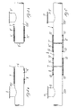
- Fig. 3a shows a first section 201 of the pipe 1, in particular the section situated on the left when viewing Figs. 1 and 2 , with the plug 4 inside it.
- the safety stopper 4" has been inserted at the end of the pipe section 201 and in the case shown is, for example, a mechanical expansion plug.
- Fig. 3b shows similarly a second section 201' of the pipe 1, in particular the section situated on the right when viewing Figs. 1 and 2 .
- the safety stopper 4'" has been inserted at the end of the pipe section 201' and in the case shown is, for example, a ball stopper.
- These pipe sections 201 and 201' are obtained by removing the damaged pipe section 101, for example along the dot-dash lines 5 and 5' shown in Figs. 1 and 2 .
- These sections 201 and 201' are normally aligned with their two free ends directed towards each other, even though in some cases the stresses from the ground which are transmitted to the pipe at the time of cutting of the pipe may cause a slight misalignment of the free ends.
- an annular chamfer 6 and 6' is formed externally on each part, i.e. on the end of the section 201 and the end of the section 201', respectively.
- Fig. 4a shows the step where, after the safety plugs have been removed, a first sliding sleeve 7 provided with at least two sealing rings 8 and 15 has been mounted on the pipe section 201 via the end with the annular chamfer 6. Similarly (see Fig. 4b ) a second sliding sleeve 7' provided with the two associated sealing rings 8' and 15' is mounted on the pipe section 201'.
- Fig. 5 shows the pipe 1 at the end of the maintenance operation according to the present method, which will be described in detail below.
- a new pipe section 9 is positioned between the free ends with annular chamfers 6 and 6' of the two pipe sections 201 and 201', said section also having its ends previously chamfered so as not to damage the seals during the sliding movement.
- the length of the new pipe section may be smaller than that of the pipe section removed since the difference in length is taken up by the distance between the sealing points of the seals 8 and 15 and 8' and 15' on the sleeve itself.
- the diameter of the new section may also be subject to a certain tolerance with respect to the existing pipe since the double seat of the seal with varying depths indicated in Fig.
- Fig. 6 shows, on a larger scale, the new pipe section 9 partially inserted inside the two sliding sleeves 7 and 7'.
- Each of these sleeves 7 and 7' (see for example the sleeve 7) comprises internally two pairs 12 and 13 of sealing rings: the first pair 12 of sealing rings is positioned around the pipe section 201, while the second pair is positioned around the pipe section 9.
- the pair 12' of sealing rings of the sleeve 7' is positioned around the pipe section 201', while the pair 13' of sealing rings is positioned around the pipe section 9.
- Annular chamfers 107 and 107' are formed internally at both the ends of each of these sleeves 7 and 7' in order to facilitate sliding thereof on the new pipe section 9 and on the two sections 201 and 201'.
- This new pipe section 9 also has externally at each end annular chamfers 109 and 109' which face, respectively, the annular chamfer 6 of the pipe section 201 and the annular chamfer 6' of the pipe section 201'.
- the purpose of these chamfers 109 and 109' is to safeguard the pairs 13 and 13' of sealing rings of the two sleeves 7 and 7' during sliding thereof on the new pipe section 9.
- welds 10 by means of which the ends of the sleeve 7' are fixed to the pipe section 201', and similar welds, which are not shown in Fig. 6 for the sake of clarity of illustration, are envisaged for the sliding sleeve 7 of the section 201. It is possible to envisage a certain spacing gap 14 and 14' between the ends of the annular chamfers 6 and 6' of the two sections 201 and 201' and the ends of the new pipe section 9.
- the new pipe section 9 is positioned between the ends with annular chamfers 6 and 6' of the two sections 201 and 201', ', so that it is aligned horizontally and vertically with them.
- the ends of this new pipe section 9 are already provided with annular chamfers 109 and 109' and are already lubricated.
Landscapes
- Engineering & Computer Science (AREA)
- General Engineering & Computer Science (AREA)
- Mechanical Engineering (AREA)
- Quick-Acting Or Multi-Walled Pipe Joints (AREA)
Claims (10)
- Verfahren zum Verbinden von Stahlrohren zum Fördern von Fluiden unter Druck mit den folgenden Schritten:a) Identifizieren eines zu ersetzenden Rohrabschnitts (101) und Unterbrechen des Fluidflusses innerhalb des Rohres (1) stromaufwärts und stromabwärts dieses Rohrabschnitts (101) mit Hilfe einer Bildung von geeigneten Punkten zum Befestigen von Stopfensystemen (4, 4'),b) nachdem der Fluidfluss unterbrochen wurde, Entfernen des zu ersetzenden Rohrabschnitts (101), so dass stromaufwärts und stromabwärts davon zwei Rohrabschnitte (201, 201') erhalten werden,c) Einfügen an dem Ende jedes Rohrabschnitts (201, 201') Schutzstopfenmittel (4", 4"'), die die Kanten der Abschnitte bestoßen und dann Befestigen einer entsprechenden gleitenden Hülse (7, 7') an jedem Rohrabschnitt (201, 201'), die im Inneren zwei Paare (12, 13, 12', 13') von Dichtringen aufweist,d) Entfernen der Schutzstopfen (4", 4"') von den Rohrabschnitten (201, 201') und Anordnen eines neuen Verbindungsstücks (9), wie z. B. einem Rohrabschnitt, einem Abzweigstück, einem Ventil oder ähnlichen, zwischen diesen,e) Verschieben der gleitenden Hülsen (7, 7') auf diesen Rohrabschnitten (201, 201'), so dass das erste Paar (12, 12') von Dichtringen um den zugeordneten Rohrabschnitt (201, 201') angeordnet ist, während das zweite Paar (13, 13') um das neue Verbindungsstück (9) angeordnet ist,f) Befestigen dieser verschiebbaren Hülsen (7, 7') an diesen Rohrabschnitten (201, 201') und an diesem Verbindungsstück (9).
- Verfahren nach Anspruch 1, dadurch gekennzeichnet, dass die Dichtringe in einem doppelten Sitz mit verschiedenen Tiefen angeordnet sind.
- Verfahren nach Anspruch 1, darüber hinaus dadurch gekennzeichnet, dass während dem Schritt a) rohrförmige Verbindungselemente (3, 3') an der Hülse des Rohrs (1) stromaufwärts und stromabwärts von dem zu ersetzenden Rohrabschnitt (101) befestigt werden, so dass das Einfügen mindestens eines Stopfens (4, 4'), der stromaufwärts und stromabwärts von dem zu ersetzenden Rohrabschnitt (101) angeordnet ist, innerhalb davon ermöglicht wird, um den Fluss in dem Rohr (1) zu unterbrechen.
- Verfahren nach Anspruch 1, dadurch gekennzeichnet, dass ringförmige Fasen (107, 107') im Inneren an beiden Enden jeder der Hülsen (7, 7') gebildet werden.
- Verfahren nach Anspruch 1, dadurch gekennzeichnet, dass während Schritt c) die gleitenden Hülsen (7, 7') vollständig auf dem zugeordneten Rohrabschnitt (201, 201'), befestigt werden.
- Verfahren nach Anspruch 1, dadurch gekennzeichnet, dass vor dem Schritt a) jedwede übermäßige Ovalisierung des Rohrs (1) überprüft wird und wenn notwendig korrigiert wird.
- Verfahren nach Anspruch 1, dadurch gekennzeichnet, dass ringförmige Fasen (6, 6') außerhalb an den freien Enden der Rohrabschnitte (201, 201'), die gemäß Schritt b) erhalten werden, gebildet werden.
- Verfahren nach Anspruch 1, dadurch gekennzeichnet, dass die Enden des neuen Verbindungsstücks (9) abgeschmiert werden und ringförmige Fasen (109, 109') auf dem Äußeren davon gebildet werden.
- Verfahren nach Anspruch 1, dadurch gekennzeichnet, dass während dem Positionierschritt d) das neue Verbindungsteil (9) horizontal und vertikal mit den Rohrabschnitten (201, 201') ausgerichtet wird.
- Verfahren nach Anspruch 1, dadurch gekennzeichnet, dass die auf den Rohrabschnitten (201, 201') und auf dem neuen Verbindungsstück (9) angeordneten gleitenden Hülsen (7, 7') an den äußeren Oberflächen davon mit Hilfe von Schweißnähten (10) befestigt werden.
Priority Applications (2)
| Application Number | Priority Date | Filing Date | Title |
|---|---|---|---|
| AT08151790T ATE515662T1 (de) | 2008-02-22 | 2008-02-22 | Verfahren zur verbindung von stahlrohren zur druckförderung von fluiden |
| EP08151790A EP2096347B1 (de) | 2008-02-22 | 2008-02-22 | Verfahren zur Verbindung von Stahlrohren zur Druckförderung von Fluiden |
Applications Claiming Priority (1)
| Application Number | Priority Date | Filing Date | Title |
|---|---|---|---|
| EP08151790A EP2096347B1 (de) | 2008-02-22 | 2008-02-22 | Verfahren zur Verbindung von Stahlrohren zur Druckförderung von Fluiden |
Publications (2)
| Publication Number | Publication Date |
|---|---|
| EP2096347A1 EP2096347A1 (de) | 2009-09-02 |
| EP2096347B1 true EP2096347B1 (de) | 2011-07-06 |
Family
ID=39591825
Family Applications (1)
| Application Number | Title | Priority Date | Filing Date |
|---|---|---|---|
| EP08151790A Not-in-force EP2096347B1 (de) | 2008-02-22 | 2008-02-22 | Verfahren zur Verbindung von Stahlrohren zur Druckförderung von Fluiden |
Country Status (2)
| Country | Link |
|---|---|
| EP (1) | EP2096347B1 (de) |
| AT (1) | ATE515662T1 (de) |
Families Citing this family (3)
| Publication number | Priority date | Publication date | Assignee | Title |
|---|---|---|---|---|
| BE1023398B1 (nl) * | 2015-09-04 | 2017-03-06 | Ebema Naamloze Vennootschap | Gootsysteem en gootelement en koppelstuk daarbij toegepast. |
| CN108105487B (zh) * | 2018-01-23 | 2022-03-08 | 中国科学院武汉病毒研究所 | 一种用于高级别防护实验室排放活毒废水的双层套管 |
| CN113618331A (zh) * | 2021-07-24 | 2021-11-09 | 浙江景迈环境工程有限公司 | 一种排水管道修复工艺 |
Family Cites Families (7)
| Publication number | Priority date | Publication date | Assignee | Title |
|---|---|---|---|---|
| US3600010A (en) * | 1969-04-01 | 1971-08-17 | Williamson Inc T | Pipe coupling |
| DE3423952A1 (de) * | 1984-06-29 | 1986-01-09 | MANIBS R. Mannesmann GmbH & ibs Nagel GmbH & Co KG, 5630 Remscheid | Muffe zum verbinden von rohrenden einer gasleitung |
| CA1250027A (en) * | 1986-02-25 | 1989-02-14 | Interprovincial Pipe Line Company, A Division Of Interhome Energy Inc. | Process for welding pipe ends and an insulating ring therefor |
| DE19542114C1 (de) * | 1995-11-11 | 1996-12-05 | Friatec Keramik Kunststoff | Anordnung zur Reparatur eines Rohres aus schweißbarem Kunststoff |
| DE19722275C2 (de) * | 1997-05-28 | 2000-09-21 | Wavin Bv | Verbindung von Kunststoffrohrteilen |
| US6241424B1 (en) * | 1998-03-17 | 2001-06-05 | Sonsub Inc. | Method and apparatus for replacing damaged section of a subsea pipeline without loss of product or entry of seawater |
| DE202004001554U1 (de) * | 2004-02-03 | 2004-04-29 | Weidner, Manfred | Reparaturset für Kunststoffrohrleitungen |
-
2008
- 2008-02-22 AT AT08151790T patent/ATE515662T1/de not_active IP Right Cessation
- 2008-02-22 EP EP08151790A patent/EP2096347B1/de not_active Not-in-force
Also Published As
| Publication number | Publication date |
|---|---|
| ATE515662T1 (de) | 2011-07-15 |
| EP2096347A1 (de) | 2009-09-02 |
Similar Documents
| Publication | Publication Date | Title |
|---|---|---|
| US8117724B2 (en) | Method for joining together steel pipes for conveying fluids under pressure | |
| US6719186B2 (en) | Method and apparatus for end-to-end welding of lined pipe | |
| US4127287A (en) | Pipe joints | |
| US20120175872A1 (en) | Pipe joining device | |
| US4281859A (en) | Pipe joints | |
| KR20150063141A (ko) | 관 조인트 | |
| US9909695B2 (en) | Joint lock ring system for lined pipes | |
| CA2365867A1 (en) | Joining of reinforced thermoplastic pipe (rtp) for high pressure transportation applications | |
| EP1373774B1 (de) | Verfahren zur verlegung von pipe-in-pipe bauwerken und vorrichtung dafür | |
| US20140117663A1 (en) | Pipe connection to form a liquid tight seal and method of forming the same | |
| GB2588919A (en) | Improved methods for joining lines pipes and associated apparatus | |
| BR112017012082B1 (pt) | método para produzir tubo rígido revestido mecanicamente e junta de tubo rígido de tubo revestido mecanicamente | |
| EP2096347A1 (de) | Verfahren zur Verbindung von Stahlrohren zur Druckförderung von Fluiden | |
| GB2543026A (en) | Improvements relating to polymer lined pipes | |
| WO1999064222A1 (en) | Pipe lining | |
| CN110307442A (zh) | 哈夫节辅助防脱装置 | |
| EP3153758B1 (de) | Gebündelte rohrsysteme | |
| RU151352U1 (ru) | Устройство защиты сварного шва трубопровода, соединенного из труб разной толщины стенок | |
| CA2623005A1 (en) | Method for joining together steel pipes for conveying fluids under pressure | |
| EP1787055A1 (de) | Elektroschweissmuffe | |
| RU2339866C2 (ru) | Способ ремонта трубопровода | |
| RU2708762C1 (ru) | Способ ремонта трубопроводов с внутренним антикоррозийным покрытием | |
| RU2628972C2 (ru) | Способ ремонта трубопровода, смонтированного из труб с внутренним покрытием | |
| EP0580799A4 (en) | Elbow fittings for double containment pipe assemblies | |
| WO2022007264A1 (zh) | 连接管组件、输送管组件、修复输送管连接接头的方法以及修复输送管的方法 |
Legal Events
| Date | Code | Title | Description |
|---|---|---|---|
| PUAI | Public reference made under article 153(3) epc to a published international application that has entered the european phase |
Free format text: ORIGINAL CODE: 0009012 |
|
| AK | Designated contracting states |
Kind code of ref document: A1 Designated state(s): AT BE BG CH CY CZ DE DK EE ES FI FR GB GR HR HU IE IS IT LI LT LU LV MC MT NL NO PL PT RO SE SI SK TR |
|
| AX | Request for extension of the european patent |
Extension state: AL BA MK RS |
|
| 17P | Request for examination filed |
Effective date: 20100215 |
|
| 17Q | First examination report despatched |
Effective date: 20100311 |
|
| AKX | Designation fees paid |
Designated state(s): AT BE BG CH CY CZ DE DK EE ES FI FR GB GR HR HU IE IS IT LI LT LU LV MC MT NL NO PL PT RO SE SI SK TR |
|
| GRAP | Despatch of communication of intention to grant a patent |
Free format text: ORIGINAL CODE: EPIDOSNIGR1 |
|
| RAP1 | Party data changed (applicant data changed or rights of an application transferred) |
Owner name: HERA S.P.A. |
|
| GRAS | Grant fee paid |
Free format text: ORIGINAL CODE: EPIDOSNIGR3 |
|
| GRAA | (expected) grant |
Free format text: ORIGINAL CODE: 0009210 |
|
| AK | Designated contracting states |
Kind code of ref document: B1 Designated state(s): AT BE BG CH CY CZ DE DK EE ES FI FR GB GR HR HU IE IS IT LI LT LU LV MC MT NL NO PL PT RO SE SI SK TR |
|
| REG | Reference to a national code |
Ref country code: GB Ref legal event code: FG4D |
|
| REG | Reference to a national code |
Ref country code: CH Ref legal event code: EP |
|
| REG | Reference to a national code |
Ref country code: IE Ref legal event code: FG4D |
|
| REG | Reference to a national code |
Ref country code: DE Ref legal event code: R096 Ref document number: 602008008056 Country of ref document: DE Effective date: 20110825 |
|
| REG | Reference to a national code |
Ref country code: NL Ref legal event code: VDEP Effective date: 20110706 |
|
| PG25 | Lapsed in a contracting state [announced via postgrant information from national office to epo] |
Ref country code: SI Free format text: LAPSE BECAUSE OF FAILURE TO SUBMIT A TRANSLATION OF THE DESCRIPTION OR TO PAY THE FEE WITHIN THE PRESCRIBED TIME-LIMIT Effective date: 20110706 |
|
| REG | Reference to a national code |
Ref country code: AT Ref legal event code: MK05 Ref document number: 515662 Country of ref document: AT Kind code of ref document: T Effective date: 20110706 |
|
| PG25 | Lapsed in a contracting state [announced via postgrant information from national office to epo] |
Ref country code: HR Free format text: LAPSE BECAUSE OF FAILURE TO SUBMIT A TRANSLATION OF THE DESCRIPTION OR TO PAY THE FEE WITHIN THE PRESCRIBED TIME-LIMIT Effective date: 20110706 Ref country code: BE Free format text: LAPSE BECAUSE OF FAILURE TO SUBMIT A TRANSLATION OF THE DESCRIPTION OR TO PAY THE FEE WITHIN THE PRESCRIBED TIME-LIMIT Effective date: 20110706 Ref country code: NL Free format text: LAPSE BECAUSE OF FAILURE TO SUBMIT A TRANSLATION OF THE DESCRIPTION OR TO PAY THE FEE WITHIN THE PRESCRIBED TIME-LIMIT Effective date: 20110706 Ref country code: LT Free format text: LAPSE BECAUSE OF FAILURE TO SUBMIT A TRANSLATION OF THE DESCRIPTION OR TO PAY THE FEE WITHIN THE PRESCRIBED TIME-LIMIT Effective date: 20110706 Ref country code: PT Free format text: LAPSE BECAUSE OF FAILURE TO SUBMIT A TRANSLATION OF THE DESCRIPTION OR TO PAY THE FEE WITHIN THE PRESCRIBED TIME-LIMIT Effective date: 20111107 Ref country code: FI Free format text: LAPSE BECAUSE OF FAILURE TO SUBMIT A TRANSLATION OF THE DESCRIPTION OR TO PAY THE FEE WITHIN THE PRESCRIBED TIME-LIMIT Effective date: 20110706 Ref country code: IS Free format text: LAPSE BECAUSE OF FAILURE TO SUBMIT A TRANSLATION OF THE DESCRIPTION OR TO PAY THE FEE WITHIN THE PRESCRIBED TIME-LIMIT Effective date: 20111106 Ref country code: NO Free format text: LAPSE BECAUSE OF FAILURE TO SUBMIT A TRANSLATION OF THE DESCRIPTION OR TO PAY THE FEE WITHIN THE PRESCRIBED TIME-LIMIT Effective date: 20111006 Ref country code: SE Free format text: LAPSE BECAUSE OF FAILURE TO SUBMIT A TRANSLATION OF THE DESCRIPTION OR TO PAY THE FEE WITHIN THE PRESCRIBED TIME-LIMIT Effective date: 20110706 |
|
| PG25 | Lapsed in a contracting state [announced via postgrant information from national office to epo] |
Ref country code: AT Free format text: LAPSE BECAUSE OF FAILURE TO SUBMIT A TRANSLATION OF THE DESCRIPTION OR TO PAY THE FEE WITHIN THE PRESCRIBED TIME-LIMIT Effective date: 20110706 Ref country code: CY Free format text: LAPSE BECAUSE OF FAILURE TO SUBMIT A TRANSLATION OF THE DESCRIPTION OR TO PAY THE FEE WITHIN THE PRESCRIBED TIME-LIMIT Effective date: 20110706 Ref country code: GR Free format text: LAPSE BECAUSE OF FAILURE TO SUBMIT A TRANSLATION OF THE DESCRIPTION OR TO PAY THE FEE WITHIN THE PRESCRIBED TIME-LIMIT Effective date: 20111007 Ref country code: LV Free format text: LAPSE BECAUSE OF FAILURE TO SUBMIT A TRANSLATION OF THE DESCRIPTION OR TO PAY THE FEE WITHIN THE PRESCRIBED TIME-LIMIT Effective date: 20110706 Ref country code: PL Free format text: LAPSE BECAUSE OF FAILURE TO SUBMIT A TRANSLATION OF THE DESCRIPTION OR TO PAY THE FEE WITHIN THE PRESCRIBED TIME-LIMIT Effective date: 20110706 |
|
| PG25 | Lapsed in a contracting state [announced via postgrant information from national office to epo] |
Ref country code: SK Free format text: LAPSE BECAUSE OF FAILURE TO SUBMIT A TRANSLATION OF THE DESCRIPTION OR TO PAY THE FEE WITHIN THE PRESCRIBED TIME-LIMIT Effective date: 20110706 Ref country code: CZ Free format text: LAPSE BECAUSE OF FAILURE TO SUBMIT A TRANSLATION OF THE DESCRIPTION OR TO PAY THE FEE WITHIN THE PRESCRIBED TIME-LIMIT Effective date: 20110706 |
|
| PLBE | No opposition filed within time limit |
Free format text: ORIGINAL CODE: 0009261 |
|
| STAA | Information on the status of an ep patent application or granted ep patent |
Free format text: STATUS: NO OPPOSITION FILED WITHIN TIME LIMIT |
|
| PG25 | Lapsed in a contracting state [announced via postgrant information from national office to epo] |
Ref country code: RO Free format text: LAPSE BECAUSE OF FAILURE TO SUBMIT A TRANSLATION OF THE DESCRIPTION OR TO PAY THE FEE WITHIN THE PRESCRIBED TIME-LIMIT Effective date: 20110706 Ref country code: EE Free format text: LAPSE BECAUSE OF FAILURE TO SUBMIT A TRANSLATION OF THE DESCRIPTION OR TO PAY THE FEE WITHIN THE PRESCRIBED TIME-LIMIT Effective date: 20110706 Ref country code: IT Free format text: LAPSE BECAUSE OF FAILURE TO SUBMIT A TRANSLATION OF THE DESCRIPTION OR TO PAY THE FEE WITHIN THE PRESCRIBED TIME-LIMIT Effective date: 20110706 |
|
| 26N | No opposition filed |
Effective date: 20120411 |
|
| PG25 | Lapsed in a contracting state [announced via postgrant information from national office to epo] |
Ref country code: DK Free format text: LAPSE BECAUSE OF FAILURE TO SUBMIT A TRANSLATION OF THE DESCRIPTION OR TO PAY THE FEE WITHIN THE PRESCRIBED TIME-LIMIT Effective date: 20110706 |
|
| REG | Reference to a national code |
Ref country code: DE Ref legal event code: R097 Ref document number: 602008008056 Country of ref document: DE Effective date: 20120411 |
|
| PG25 | Lapsed in a contracting state [announced via postgrant information from national office to epo] |
Ref country code: MC Free format text: LAPSE BECAUSE OF NON-PAYMENT OF DUE FEES Effective date: 20120229 |
|
| REG | Reference to a national code |
Ref country code: CH Ref legal event code: PL |
|
| PG25 | Lapsed in a contracting state [announced via postgrant information from national office to epo] |
Ref country code: CH Free format text: LAPSE BECAUSE OF NON-PAYMENT OF DUE FEES Effective date: 20120229 Ref country code: LI Free format text: LAPSE BECAUSE OF NON-PAYMENT OF DUE FEES Effective date: 20120229 |
|
| REG | Reference to a national code |
Ref country code: IE Ref legal event code: MM4A |
|
| PG25 | Lapsed in a contracting state [announced via postgrant information from national office to epo] |
Ref country code: IE Free format text: LAPSE BECAUSE OF NON-PAYMENT OF DUE FEES Effective date: 20120222 |
|
| PG25 | Lapsed in a contracting state [announced via postgrant information from national office to epo] |
Ref country code: ES Free format text: LAPSE BECAUSE OF FAILURE TO SUBMIT A TRANSLATION OF THE DESCRIPTION OR TO PAY THE FEE WITHIN THE PRESCRIBED TIME-LIMIT Effective date: 20111017 |
|
| PG25 | Lapsed in a contracting state [announced via postgrant information from national office to epo] |
Ref country code: BG Free format text: LAPSE BECAUSE OF FAILURE TO SUBMIT A TRANSLATION OF THE DESCRIPTION OR TO PAY THE FEE WITHIN THE PRESCRIBED TIME-LIMIT Effective date: 20111006 |
|
| PG25 | Lapsed in a contracting state [announced via postgrant information from national office to epo] |
Ref country code: MT Free format text: LAPSE BECAUSE OF FAILURE TO SUBMIT A TRANSLATION OF THE DESCRIPTION OR TO PAY THE FEE WITHIN THE PRESCRIBED TIME-LIMIT Effective date: 20110706 |
|
| PG25 | Lapsed in a contracting state [announced via postgrant information from national office to epo] |
Ref country code: TR Free format text: LAPSE BECAUSE OF FAILURE TO SUBMIT A TRANSLATION OF THE DESCRIPTION OR TO PAY THE FEE WITHIN THE PRESCRIBED TIME-LIMIT Effective date: 20110706 |
|
| PG25 | Lapsed in a contracting state [announced via postgrant information from national office to epo] |
Ref country code: LU Free format text: LAPSE BECAUSE OF NON-PAYMENT OF DUE FEES Effective date: 20120222 |
|
| PGFP | Annual fee paid to national office [announced via postgrant information from national office to epo] |
Ref country code: FR Payment date: 20140218 Year of fee payment: 7 |
|
| PGFP | Annual fee paid to national office [announced via postgrant information from national office to epo] |
Ref country code: GB Payment date: 20140221 Year of fee payment: 7 |
|
| PG25 | Lapsed in a contracting state [announced via postgrant information from national office to epo] |
Ref country code: HU Free format text: LAPSE BECAUSE OF FAILURE TO SUBMIT A TRANSLATION OF THE DESCRIPTION OR TO PAY THE FEE WITHIN THE PRESCRIBED TIME-LIMIT Effective date: 20080222 |
|
| PGFP | Annual fee paid to national office [announced via postgrant information from national office to epo] |
Ref country code: DE Payment date: 20140419 Year of fee payment: 7 |
|
| REG | Reference to a national code |
Ref country code: DE Ref legal event code: R119 Ref document number: 602008008056 Country of ref document: DE |
|
| GBPC | Gb: european patent ceased through non-payment of renewal fee |
Effective date: 20150222 |
|
| REG | Reference to a national code |
Ref country code: FR Ref legal event code: ST Effective date: 20151030 |
|
| PG25 | Lapsed in a contracting state [announced via postgrant information from national office to epo] |
Ref country code: GB Free format text: LAPSE BECAUSE OF NON-PAYMENT OF DUE FEES Effective date: 20150222 Ref country code: DE Free format text: LAPSE BECAUSE OF NON-PAYMENT OF DUE FEES Effective date: 20150901 |
|
| PG25 | Lapsed in a contracting state [announced via postgrant information from national office to epo] |
Ref country code: FR Free format text: LAPSE BECAUSE OF NON-PAYMENT OF DUE FEES Effective date: 20150302 |