EP2096357A1 - Accroche flamme pour canal de réchauffe d'un turboréacteur avec une semelle d'écartement, canal de réchauffe et turboréacteur comprenant un canal de réchauffe - Google Patents
Accroche flamme pour canal de réchauffe d'un turboréacteur avec une semelle d'écartement, canal de réchauffe et turboréacteur comprenant un canal de réchauffe Download PDFInfo
- Publication number
- EP2096357A1 EP2096357A1 EP09153848A EP09153848A EP2096357A1 EP 2096357 A1 EP2096357 A1 EP 2096357A1 EP 09153848 A EP09153848 A EP 09153848A EP 09153848 A EP09153848 A EP 09153848A EP 2096357 A1 EP2096357 A1 EP 2096357A1
- Authority
- EP
- European Patent Office
- Prior art keywords
- flame
- arm
- box
- sole
- injector
- Prior art date
- Legal status (The legal status is an assumption and is not a legal conclusion. Google has not performed a legal analysis and makes no representation as to the accuracy of the status listed.)
- Granted
Links
Images


Classifications
-
- F—MECHANICAL ENGINEERING; LIGHTING; HEATING; WEAPONS; BLASTING
- F23—COMBUSTION APPARATUS; COMBUSTION PROCESSES
- F23R—GENERATING COMBUSTION PRODUCTS OF HIGH PRESSURE OR HIGH VELOCITY, e.g. GAS-TURBINE COMBUSTION CHAMBERS
- F23R3/00—Continuous combustion chambers using liquid or gaseous fuel
- F23R3/02—Continuous combustion chambers using liquid or gaseous fuel characterised by the air-flow or gas-flow configuration
- F23R3/16—Continuous combustion chambers using liquid or gaseous fuel characterised by the air-flow or gas-flow configuration with devices inside the flame tube or the combustion chamber to influence the air or gas flow
- F23R3/18—Flame stabilising means, e.g. flame holders for after-burners of jet-propulsion plants
- F23R3/20—Flame stabilising means, e.g. flame holders for after-burners of jet-propulsion plants incorporating fuel injection means
Definitions
- the present invention relates to the field of turbojet engines comprising a heating channel of gases from the gas generator.
- the post-combustion jet engines comprise, from upstream to downstream, a gas generator consisting of a gas turbine engine producing combustion-heated gases, a heating channel and an exhaust nozzle for the gases in the atmosphere.
- the engine is most often double-stream with a central primary flow and a peripheral secondary flow.
- the heating channel is provided with a jacket made of material resistant to the gas combustion temperature and suitably cooled.
- fuel injection means are arranged in the gas stream, associated with means forming flame hangers.
- the flame catching means 10 are in the form of radial arms arranged in a star with respect to the motor axis and passing through the two primary and secondary flow veins, interconnected by elements in the form of annular sectors 9.
- the arms 100 cast from the channel-shaped foundry have a section U or V open downstream so as to create a depressed area to stabilize the combustion.
- fuel injectors 130 are placed inside the cavity formed between the walls, upstream and near the top with air ventilation boxes 120. The air is taken from the secondary flow and distributed by the caissons 120 towards the injectors 130.
- a thermal protection screen 110 is placed on the cover of this part of the arm 100 containing the fuel injectors 130 and the ventilation box 120.
- the air ventilation box 120 is centered in the upper part and in the lower part in the cavity of the arm 100. It is held in radial position by means of a pin 5 on the base of the tube which passes through the thermal protection screen 110 and thereby ensures a rotational stop of the box 120 in the arm 100.
- the thermal protection screen 110 which is generally made of CMC (composite ceramic material) is damaged by matting and delamination which is particularly harmful in vibration operation.
- the Applicant proposes, in order to fill at least some of these drawbacks, a heater flame hook for which it is not necessary to perform machining in the body of the arm 100 and / or the heat shield 120, which weaken mechanically and / or thermally the flame catch.
- a flame catch is simple design and easy assembly which reduces its cost.
- it offers increased thermal and mechanical resistance due to the absence of areas of weakness.
- the invention relates to a flame-holder for a turbojet's heating channel comprising a trough-shaped channel forming a cavity, a heat shield of the arm cavity and an air supply box housed in the cavity, characterized in that the arm, the protective shield and the air supply box are held together by a monoblock spacer having at least one spacer lug arranged to provide an air gap (e) between the screen thermal protection and at least one wall of the arm.
- the air gap ear advantageously provides a channel between the shield and the arm to allow the passage of carbureted air.
- the sole comprises means for holding the box.
- the soleplate advantageously allows the box to be held without weakening the arm or its thermal protection screen.
- a fuel injector is placed inside said arm cavity.
- the sole comprises means for centering the injector.
- the soleplate advantageously allows the injector to be centered without weakening the arm or its thermal protection screen. This advantageously still allows to maintain a constant distance between the injector and the air box which facilitates the air distribution of the air box towards the injectors.
- the soleplate is welded to the air supply box which makes it possible to prevent any translation of the box into the arm.
- the sole is in the form of a Y defining a central branch and two lateral branches, the central branch comprising a through hole for holding the box.
- the shape of the soleplate advantageously makes it possible to overcome the differential expansions between the arm and the sole.
- the through hole for holding the box advantageously allows to guide and block the air box.
- the central branch comprises a through hole for centering the injector.
- the invention relates to a turbojet heater heat pipe comprising at least one such flame catch.
- the invention also relates to a turbojet engine comprising such a heating channel.
- the figure 2 represents a part of a turbofan engine.
- This engine only shows the ogival shape of the exhaust casing 3 at the rear of the gas turbine engine, inside the outer cylindrical casing 4.
- the engine provides output of the engine turbine gas turbine, a hot primary gas flow, represented by the arrow P.
- Part of the air sucked by the engine is simply compressed and bypasses the combustion chamber of the engine. This air constitutes the secondary flow, represented by the arrow S.
- the two streams are mixed here downstream of a confluence section formed of an annular sheet.
- This engine section is extended, in particular military-type aircraft, by a cylindrical heating channel 1 of the gas before the ejection nozzle. We see the upstream part of the heating channel 1 but not the nozzle. In certain flight phases, it is necessary to provide additional energy to the gases producing the thrust. This is provided by the heating, also called afterburning, gases in the heating channel. Fuel is injected into the gases by injectors such as those shown at 7, radially crossing the two veins, primary and secondary. Downstream of these Injectors, means forming flame hangers 10 are shaped so as to allow the retention of gases the time of their combustion.
- These means comprise linearly radially star-shaped flame catchers 10 arranged in a plane substantially perpendicular to the motor axis, here immediately downstream of the confluence of the two primary and secondary flows. They are connected by ring sector arms 9 which, according to this type of heating device, are on the side of the secondary vein.
- the radial flame hooks 10 are formed of radial arms 100 in the form of a chute, with a V or U-shaped cross-section, the edge of which is turned upstream with respect to the direction of flow of the gases.
- the structure of the flame catch 10 is visible on the section of the figure 5 according to direction II-II of the figure 4 .
- the arm 100 defines a cavity, between the upstream edge and the free downstream edges of the two walls 101a and 101b, occupied by an air supply box 120 taken from the vein of the secondary flow, a tubular injector 130 of fuel and a 110 thermal protection screen.
- the screen 110 is shaped curved plate whose concavity is facing downstream.
- the air supply box 120, the tubular fuel injector 130 and the thermal protection screen 110 are held in the arm 100, at the top, in the heating case and, at the bottom, by a rubber sole. spacing 150 whose role is to prevent them from being in contact, particularly in vibration operation.
- the soleplate 150 makes it possible to fix the air supply box 120 and the injector 130 in the arm 100 without the need for drilling in zones thermally stressed both of the screen 110 and of the arm 100, which makes it possible to limit wear. .
- the arm 100 and the tubular fuel injector 130 are directly fixed in the heating case.
- the spacer sole 150 is substantially in the form of a Y comprising a central branch 150c, extending in its length in a direction X, which extend two lateral branches 150a, 150b substantially parallel.
- Each lateral branch 150a, 150b, extending in the direction X, is terminated at its end by a circular spacer lug 151a, 151b each comprising a fixing orifice 152a, 152b arranged in the lateral branch 150a, 150b in a direction Y, orthogonal to the direction X.
- the lateral branches 150a, 150b are of small thickness so as to be able to overcome the differential expansions between the arm 100 CMC and the sole 150 of metal. This also applies to an arm made of metallic material, differential expansions appearing because of the temperature differences between the metal parts.
- the central branch 150c of the spacer sole 150 wider than the lateral branches 150a, 150b, is pierced at two places in its thickness along a direction Z.
- a first through-hole 154 is provided at the base of the branch 150c and is intended to maintain an axial portion of the air supply box 120. This orifice will be designated thereafter holding orifice of the caisson 154.
- a second through-hole for holding 156 is formed in the central branch 150c, between the holding orifice of the caisson 154 and the lateral branches 150a, 150b. This orifice 156 is intended to center the tubular fuel injector 130 in the arm 100. This orifice will be designated hereinafter the centering orifice of the injector 156.
- the spacer sole 150 also has through-blocking orifices 155 formed in the width of the central branch 150c in the Y direction, orthogonal to the holding orifice of the caisson 154.
- the outer surface of the box 120 is visible via the blocking orifices 155 whose function will be detailed later. .
- the air supply box 120 and the tubular fuel injector 130 are centered in the upper part in the flame hook 10 and held in the lower part by the spacer sole 150.
- the air box 120 comprises, in the upper part, a swiveling head, allowing its centering in the arm.
- the air supply box 120 is introduced axially, in the Z direction, into the spacing plate 150 via its holding orifice of the box 154 and is locked axially with the soleplate 150 by welding. During the welding step, material is provided on the outer surface of the box 120 which is visible via the locking holes 155.
- the air box 120 is then fixedly held by the soleplate 150 as shown in FIG. figure 7 .
- the tubular fuel injector 130 is, for its part, introduced axially in the direction Z into the centering orifice of the injector 156 in order to keep it away from the air supply box 120.
- the distance between the casing 120 and the injector can be parameterized by adjusting the distance between the centering orifice of the injector 156 and the holding orifice of the casing 154 of the soleplate 150.
- the circular air gap lugs 151a, 151b of the spacer sole 150 are arranged between the walls of the protective shield 110 and the walls of the arm 100.
- the lug 151a is interposed between the wall 111a of the protection screen 110 and the wall 101a of the arm 100, the thickness of the lug 151a defining an air gap thickness (e) between said walls 101a, 111a.
- the gap (e) forms a channel allowing the passage of carbureted air.
- a cylindrical pin 160 passes successively through the wall 111a of the screen 110, the fixing orifice 152a of the lug and the wall 101a of the arm 100.
- the lug 160 is retained by a washer 161 welded externally to the arm 100.
- the assembly formed by the wall 101a of the arm 100, the wall 111a of the screen 110 and the lug 151a is held tight between the welded washer 161 and the head of the cylindrical pin 162.
Landscapes
- Engineering & Computer Science (AREA)
- Chemical & Material Sciences (AREA)
- Combustion & Propulsion (AREA)
- Mechanical Engineering (AREA)
- General Engineering & Computer Science (AREA)
- Fuel-Injection Apparatus (AREA)
- Structures Of Non-Positive Displacement Pumps (AREA)
- Gas Burners (AREA)
- Turbine Rotor Nozzle Sealing (AREA)
Abstract
Description
- La présente invention concerne le domaine des turboréacteurs comprenant un canal de réchauffe des gaz issus du générateur de gaz.
- Les turboréacteurs à post combustion comprennent d'amont en aval un générateur de gaz, constitué par un moteur à turbine à gaz, produisant des gaz chauffés par combustion, un canal de réchauffe et une tuyère d'échappement des gaz dans l'atmosphère. Le moteur est le plus souvent à double flux avec un flux primaire central et un flux secondaire périphérique.
- Le canal de réchauffe est pourvu d'une chemise en matériau résistant à la température de combustion des gaz et convenablement refroidie. En entrée du canal des moyens d'injection de carburant sont disposés dans la veine de gaz, associés à des moyens formant accroche flammes.
- En référence à la
figure 1 , les moyens d'accroche flammes 10 sont en forme de bras radiaux disposés en étoile par rapport à l'axe moteur et traversant les deux veines de flux primaire et secondaire, reliés entre eux par des éléments en forme de secteurs annulaires 9. En référence à lafigure 2 , les bras 100 venus de fonderie en forme de goulotte ont une section en U ou en V ouverte vers l'aval de manière à créer une zone en dépression apte à y stabiliser la combustion. Dans une partie au moins des accroche flammes 10, des injecteurs de carburant 130 sont placés à l'intérieur dans la cavité ménagée entre les parois, en amont et à proximité du sommet avec des caissons de ventilation d'air 120. L'air est prélevé dans le flux secondaire et distribué par les caissons 120 en direction des injecteurs 130. Afin de protéger ces éléments, un écran de protection thermique 110 est placé en couverture de cette partie du bras 100 contenant les injecteurs de carburant 130 et le caisson de ventilation 120. - Traditionnellement, comme représenté sur la
figure 2 , le caisson de ventilation d'air 120 est centré en partie haute et en partie basse dans la cavité du bras 100. Il est maintenu en position radiale par l'intermédiaire d'un tenon 5 sur l'embase du tube qui traverse l'écran de protection thermique 110 et assure de ce fait un arrêt en rotation du caisson 120 dans le bras 100. - Cependant, il n'est pas souhaitable de fragiliser l'écran thermique 110 en le perçant pour maintenir le caisson d'air 120. En effet, l'écran de protection thermique 110 qui est généralement en CMC (composite en Matière Céramique) est endommagé par matage et délaminage ce qui est particulièrement néfaste en fonctionnement vibratoire.
- De manière similaire, les perçages et les usinages réalisés dans les écrans de protection métalliques entraînent une concentration des contraintes ce qui diminue l'efficacité et la durée de vie desdits écrans.
- Il est également connu de percer le bras 100 à son extrémité basse pour y introduire le caisson de ventilation d'air 120 qui est fixé par l'intermédiaire d'une rondelle 16 soudée à l'extrémité basse du caisson de ventilation d'air 120, extérieurement au bras 100, comme représenté sur la
figure 3 . - Cette alternative n'est pas satisfaisante car elle nécessite de percer le bras 100 et donc induit tous les inconvénients cités précédemment.
- La demanderesse propose, afin de combler au moins certains de ces inconvénients, un accroche flamme de réchauffe pour lequel il n'est pas nécessaire de réaliser des usinages dans le corps du bras 100 et/ou de l'écran thermique 120, qui affaiblissent mécaniquement et/ou thermiquement l'accroche flamme. Un tel accroche flamme est de conception simple et de montage aisé ce qui diminue son coût de revient. En outre, il offre une résistance thermique et mécanique accrue de part l'absence de zones de faiblesse.
- L'invention concerne un accroche flamme pour canal de réchauffe d'un turboréacteur comprenant un bras en forme de goulotte ménageant une cavité, un écran de protection thermique de la cavité du bras et un caisson d'alimentation en air logé dans la cavité, caractérisé par le fait que le bras, l'écran de protection et le caisson d'alimentation en air sont maintenus ensemble par une semelle d'écartement monobloc comportant au moins une oreille d'entretoise agencée pour ménager un entrefer (e) entre l'écran de protection thermique et au moins une paroi du bras.
- Une telle semelle permet de maintenir des écarts entre les différents éléments ce qui évite de créer des usures lors d'un fonctionnement vibratoire.
- L'oreille d'entrefer permet avantageusement de ménager un canal entre l'écran de protection et le bras afin de permettre le passage de l'air carburé.
- De préférence toujours, la semelle comporte un moyen de maintien du caisson.
- La semelle permet avantageusement de maintenir le caisson sans fragiliser le bras ou son écran de protection thermique.
- Selon une forme de réalisation de l'invention, un injecteur de carburant est placé à l'intérieur de ladite cavité du bras.
- De préférence, la semelle comporte un moyen de centrage de l'injecteur.
- La semelle permet avantageusement de centrer l'injecteur sans fragiliser le bras ou son écran de protection thermique. Cela permet avantageusement encore de maintenir une distance constante entre l'injecteur et le caisson d'air ce qui facilite la distribution d'air du caisson d'air en direction des injecteurs.
- De préférence, la semelle est soudée au caisson d'alimentation en air ce qui permet d'éviter toute translation du caisson dans le bras.
- De préférence encore, la semelle se présente sous la forme d'un Y définissant une branche centrale et deux branches latérales, la branche centrale comprenant un orifice traversant de maintien du caisson.
- La forme de la semelle permet avantageusement de s'affranchir des dilatations différentielles entre le bras et la semelle.
- L'orifice traversant de maintien du caisson permet avantageusement de guider et de bloquer le caisson d'air.
- De préférence toujours, la branche centrale comprend un orifice traversant de centrage de l'injecteur.
- L'invention concerne un canal de réchauffe de turboréacteur comprenant au moins un tel accroche flamme.
- L'invention concerne également un turboréacteur comprenant un tel canal de réchauffe.
- L'invention sera mieux comprise à l'aide des dessins en annexe sur lesquels:
- la
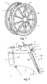
figure 1 représente une vue en perspective d'un carter de réchauffe avec des accroche flammes; - la
figure 2 représente une vue en coupe d'une partie d'un turboréacteur à double flux avec un accroche flamme selon un premier art antérieur; - la
figure 3 représente une vue en coupe de la partie basse d'un accroche flamme selon un deuxième art antérieur; - la
figure 4 représente une vue en coupe d'un accroche flamme selon l'invention; - la
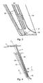
figure 5 représente une vue en coupe de l'accroche flamme de lafigure 4 selon la direction II-II; - la
figure 6 représente une vue en perspective d'une semelle d'écartement selon l'invention; - la
figure 7 représente une vue en perspective de la semelle de lafigure 6 maintenant un caisson d'alimentation en air; - la
figure 8A représente une vue en perspective partielle de la semelle et du caisson de lafigure 7 montés dans un accroche flamme; et - la
figure 8B est une vue rapprochée de lafigure 8A représentant la liaison, réalisée par la semelle, entre un bras d'accroche flamme et son écran de protection thermique. - La
figure 2 représente une partie d'un turboréacteur à double flux. On ne voit de ce moteur que la forme en ogive du carter d'échappement 3 à l'arrière du moteur à turbine à gaz, à l'intérieur de l'enveloppe cylindrique extérieure 4. Le moteur fournit en sortie de la turbine du moteur à turbine à gaz, un flux gazeux primaire chaud, représenté par la flèche P. Une partie de l'air aspiré par le moteur est simplement comprimée et contourne la chambre de combustion du moteur. Cet air constitue le flux secondaire, représenté par la flèche S. Les deux flux se mélangent ici en aval d'une section de confluence formée d'une tôle annulaire. - Cette section de moteur se prolonge, dans les aéronefs de type militaire notamment, par un canal cylindrique de réchauffe 1 des gaz avant la tuyère d'éjection. On voit la partie amont du canal de réchauffe 1 mais pas la tuyère. Dans certaines phases de vol, il est nécessaire de fournir une énergie supplémentaire aux gaz produisant la poussée. Celle-ci est apportée par la réchauffe, dite aussi postcombustion, des gaz dans le canal de réchauffe. Du carburant est injecté dans les gaz par des injecteurs comme ceux représentés en 7, traversant radialement les deux veines, primaire et secondaire. En aval de ces injecteurs, des moyens formant accroche flammes 10 sont conformés de manière à permettre la retenue des gaz le temps de leur combustion. Ces moyens comprennent des accroche flammes 10 en partie rectiligne disposés radialement en étoile dans un plan sensiblement perpendiculaire à l'axe moteur, ici immédiatement en aval de la confluence des deux flux primaire et secondaire. Ils sont reliés par des bras en secteur d'anneau 9 qui, selon ce type de dispositif de réchauffe, sont du côté de la veine secondaire.
- En référence à la
figure 4 , les accroche flammes radiaux 10 sont formés de bras radiaux 100 en forme de goulotte, à section en V ou en U, dont l'arête est tournée vers l'amont par rapport au sens d'écoulement des gaz. La structure de l'accroche flamme 10 est visible sur la coupe de lafigure 5 selon la direction II-II de lafigure 4 . Le bras 100 définit une cavité, entre l'arête amont et les bords libres aval des deux parois 101a et 101b, occupée par un caisson 120 d'alimentation en air prélevé dans la veine du flux secondaire, un injecteur 130 tubulaire de carburant et un écran 110 de protection thermique. L'écran 110 est en forme de tôle incurvée dont la concavité est tournée vers l'aval. - Le caisson 120 d'alimentation en air, l'injecteur 130 tubulaire de carburant et l'écran 110 de protection thermique sont maintenus dans le bras 100, en partie haute, dans le carter de réchauffe et, en partie basse, par une semelle d'écartement 150 dont le rôle est d'éviter que ces derniers soient en contact, en particulier en fonctionnement vibratoire. La semelle 150 permet de fixer le caisson 120 d'alimentation en air et l'injecteur 130 dans le bras 100 sans nécessité de perçages dans des zones sollicitées thermiquement aussi bien de l'écran 110 que du bras 100 ce qui permet de limiter les usures.
- Dans cet exemple, le bras 100 et l'injecteur 130 tubulaire de carburant sont directement fixés dans le carter de réchauffe.
- En référence à la
figure 6 , la semelle d'écartement 150 se présente sensiblement sous la forme d'un Y comprenant une branche centrale 150c, s'étendant dans sa longueur selon une direction X, duquel s'étendent deux branches latérales 150a, 150b sensiblement parallèles. Chaque branche latérale 150a, 150b, s'étendant selon la direction X, est terminée à son extrémité par une oreille circulaire d'entretoise 151a, 151b comprenant chacune un orifice de fixation 152a, 152b ménagé dans la branche latérale 150a, 150b selon une direction Y, orthogonale à la direction X. - Les branches latérales 150a, 150b sont d'épaisseur faible de manière à pouvoir s'affranchir des dilatations différentielles entre le bras 100 en CMC et la semelle 150 en métal. Ceci s'applique également à un bras en matière métallique, des dilatations différentielles apparaissant du fait des écarts de température entre les pièces métalliques.
- La branche centrale 150c de la semelle d'écartement 150, plus large que les branches latérales 150a, 150b, est percée à deux endroits dans son épaisseur selon une direction Z. Un premier orifice traversant de maintien 154 est ménagé à la base de la branche centrale 150c et est destiné à maintenir une portion axiale du caisson 120 d'alimentation en air. Cet orifice sera désigné par la suite orifice de maintien du caisson 154. Un deuxième orifice traversant de maintien 156 est ménagé dans la branche centrale 150c, entre l'orifice de maintien du caisson 154 et les branches latérales 150a, 150b. Cet orifice 156 est destiné à centrer l'injecteur 130 tubulaire de carburant dans le bras 100. Cet orifice sera désigné par la suite orifice de centrage de l'injecteur 156.
- Toujours en référence à la
figure 6 , la semelle d'écartement 150 comporte également des orifices traversants de blocage 155 ménagés dans la largeur de la branche centrale 150c selon la direction Y, orthogonalement à l'orifice de maintien du caisson 154. Ainsi, en référence maintenant à lafigure 7 , lorsque le caisson 120 d'alimentation en air est introduit dans la semelle d'écartement 150 via son orifice de maintien du caisson 154, la surface extérieure du caisson 120 est visible via les orifices de blocage 155 dont la fonction sera détaillée par la suite. - L'invention sera encore mieux comprise grâce à la description du montage de la semelle d'écartement 150 dans le bras 100 comme représenté sur les
figures 4 ,5 ,7, 8a et 8b . - En référence à la
figure 4 , le caisson 120 d'alimentation en air et l'injecteur 130 tubulaire de carburant sont centrés en partie haute dans l'accroche flamme 10 et maintenus en partie basse par la semelle d'écartement 150. Dans cet exemple, le caisson d'air 120 comporte, en partie haute, une tête rotulante, permettant son centrage dans le bras. Le caisson 120 d'alimentation en air est introduit axialement, selon la direction Z, dans la semelle d'écartement 150 via son orifice de maintien du caisson 154 et est bloqué axialement avec la semelle 150 par soudage. Lors de l'étape de soudage, de la matière est apportée sur la surface extérieure du caisson 120 qui est visible via les orifices de blocage 155. Le caisson d'air 120 est alors fixement maintenu par la semelle 150 comme représenté sur lafigure 7 . - L'injecteur 130 tubulaire de carburant est, quant à lui, introduit axialement selon la direction Z dans l'orifice de centrage de l'injecteur 156 afin de le maintenir à distance du caisson 120 d'alimentation en air. La distance entre le caisson 120 et l'injecteur peut être paramétrée en adaptant l'écart entre l'orifice de centrage de l'injecteur 156 et l'orifice de maintien du caisson 154 de la semelle 150.
- Lors du montage, les oreilles circulaires d'entrefer 151a, 151b de la semelle d'écartement 150 sont disposées entre les parois de l'écran de protection 110 et les parois du bras 100. En référence à la
figure 5 , l'oreille 151a est intercalée entre la paroi 111a de l'écran de protection 110 et la paroi 101a du bras 100, l'épaisseur de l'oreille 151a définissant une épaisseur d'entrefer (e) entre lesdites parois 101a, 111a. L'entrefer (e) forme un canal permettant le passage de l'air carburé. - Pour chaque oreille d'entretoise de la semelle 150, un pion 160 cylindrique traverse successivement la paroi 111a de l'écran 110, l'orifice de fixation 152a de l'oreille et la paroi 101a du bras 100. Le pion 160 est retenu par une rondelle 161 soudée extérieurement au bras 100. L'ensemble formé par la paroi 101a du bras 100, la paroi 111a de l'écran 110 et l'oreille 151a est maintenu serré entre la rondelle soudée 161 et la tête du pion cylindrique 162.
- Il va de soi que d'autres moyens de fixation pourraient également convenir tels que ceux décrits dans la demande
FR0655241 - On a décrit le montage d'un écran de protection thermique sur un accroche flamme de forme rectiligne. L'invention ne se limite pas à cette application. Ce type de montage vaut aussi pour celui d'un écran de protection thermique dans un accroche flamme en forme de secteur d'anneau tel que ceux reliant les bras radiaux.
Claims (9)
- Accroche flamme (10) pour canal de réchauffe d'un turboréacteur comprenant un bras (100) en forme de goulotte ménageant une cavité, un écran (110) de protection thermique de la cavité du bras (100) et un caisson (120) d'alimentation en air logé dans la cavité, caractérisé par le fait que le bras (100), l'écran de protection (110) et le caisson (120) d'alimentation en air sont maintenus ensemble par une semelle d'écartement monobloc (150) comportant au moins une oreille d'entretoise (151a, 151b) agencée pour ménager un entrefer (e) entre l'écran (110) de protection thermique et au moins une paroi du bras (100).
- Accroche flamme selon la revendication 1, dans lequel la semelle (150) comporte un moyen de maintien du caisson (120).
- Accroche flamme selon l'une des revendications 1 à 2, dans lequel un injecteur de carburant (130) est placé à l'intérieur de ladite cavité du bras (100).
- Accroche flamme selon la revendication 3, dans lequel la semelle (150) comporte un moyen de centrage de l'injecteur (130).
- Accroche flamme selon l'une des revendications 1 à 4, dans lequel la semelle (150) est soudée au caisson (120) d'alimentation en air.
- Accroche flamme selon l'une des revendications 1 à 5, dans lequel la semelle (150) se présente sous la forme d'un Y définissant une branche centrale (150c) et deux branches latérales (150a, 150b), la branche centrale (150c) comprenant un orifice traversant (154) de maintien du caisson (120).
- Accroche flamme selon la revendication 6 en combinaison avec la revendication 3, dans lequel la branche centrale (150c) comprend un orifice traversant (156) de centrage de l'injecteur (130).
- Canal de réchauffe de turboréacteur comprenant au moins un accroche flamme selon l'une des revendications 1 à 7.
- Turboréacteur comprenant un canal de réchauffe selon la revendication 8.
Applications Claiming Priority (1)
| Application Number | Priority Date | Filing Date | Title |
|---|---|---|---|
| FR0801138A FR2928202A1 (fr) | 2008-02-29 | 2008-02-29 | Accroche flamme pour canal de rechauffe d'un turboreacteur avec une semelle d'ecartement, canal de rechauffe et turboreacteur comprenant un canal de rechauffe. |
Publications (2)
| Publication Number | Publication Date |
|---|---|
| EP2096357A1 true EP2096357A1 (fr) | 2009-09-02 |
| EP2096357B1 EP2096357B1 (fr) | 2010-09-15 |
Family
ID=39800458
Family Applications (1)
| Application Number | Title | Priority Date | Filing Date |
|---|---|---|---|
| EP09153848A Active EP2096357B1 (fr) | 2008-02-29 | 2009-02-27 | Accroche flamme pour canal de réchauffe d'un turboréacteur avec une semelle d'écartement, canal de réchauffe et turboréacteur comprenant un canal de réchauffe |
Country Status (4)
| Country | Link |
|---|---|
| US (1) | US8307658B2 (fr) |
| EP (1) | EP2096357B1 (fr) |
| DE (1) | DE602009000173D1 (fr) |
| FR (1) | FR2928202A1 (fr) |
Cited By (1)
| Publication number | Priority date | Publication date | Assignee | Title |
|---|---|---|---|---|
| FR2950416A1 (fr) * | 2009-09-23 | 2011-03-25 | Snecma | Dispositif accroche-flammes comprenant un support de bras et un ecran de protection thermique monoblocs |
Families Citing this family (8)
| Publication number | Priority date | Publication date | Assignee | Title |
|---|---|---|---|---|
| US20140026590A1 (en) * | 2012-07-25 | 2014-01-30 | Hannes A. Alholm | Flexible combustor bracket |
| RU2520598C1 (ru) * | 2012-11-26 | 2014-06-27 | Открытое акционерное общество "Конструкторское бюро химавтоматики" | Устройство крепления теплозащиты к раме двигателя (варианты) |
| US9879862B2 (en) | 2013-03-08 | 2018-01-30 | Rolls-Royce North American Technologies, Inc. | Gas turbine engine afterburner |
| JP6340918B2 (ja) * | 2014-05-23 | 2018-06-13 | 株式会社Ihi | 推力増強装置 |
| CN104373964B (zh) * | 2014-10-20 | 2016-08-17 | 北京航空航天大学 | 内置油杆的凹腔支板火焰稳定器 |
| EP3244054B1 (fr) | 2015-06-16 | 2019-08-21 | IHI Corporation | Structure de section arrière d'un moteur à réaction |
| RU2742592C1 (ru) * | 2020-06-16 | 2021-02-08 | Акционерное общество "Конструкторское бюро химавтоматики" | Хомут кронштейна крепления агрегата к трубопроводу жидкостного ракетного двигателя |
| CN115164234B (zh) * | 2022-05-12 | 2023-06-13 | 中国航发四川燃气涡轮研究院 | 加力燃烧室火焰稳定器 |
Citations (6)
| Publication number | Priority date | Publication date | Assignee | Title |
|---|---|---|---|---|
| FR655241A (fr) | 1927-04-14 | 1929-04-16 | Thomson Houston Comp Francaise | Perfectionnements aux dispositifs de commutation des machines électriques, type métdyne |
| FR1516562A (fr) * | 1966-03-25 | 1968-03-08 | Rolls Royce | Moteur de turbine à gaz à dérivation |
| US3698186A (en) * | 1970-12-24 | 1972-10-17 | United Aircraft Corp | Afterburner combustion apparatus |
| FR2709342A1 (fr) * | 1993-08-25 | 1995-03-03 | Snecma | Dispositif de post combustion d'un turboréacteur. |
| EP1593911A1 (fr) * | 2004-05-05 | 2005-11-09 | Snecma | Dispositif d'alimentation en air et en carburant d'un anneau-brûleur dans une chambre de postcombustion |
| EP1840469A1 (fr) * | 2006-03-30 | 2007-10-03 | Snecma | Bras accroche-flammes d'une chambre de post-combustion |
Family Cites Families (4)
| Publication number | Priority date | Publication date | Assignee | Title |
|---|---|---|---|---|
| GB1139005A (en) * | 1966-03-25 | 1969-01-08 | Rolls Royce | Improvements in or relating to gas turbine by-pass engines |
| US5396761A (en) * | 1994-04-25 | 1995-03-14 | General Electric Company | Gas turbine engine ignition flameholder with internal impingement cooling |
| US5396763A (en) * | 1994-04-25 | 1995-03-14 | General Electric Company | Cooled spraybar and flameholder assembly including a perforated hollow inner air baffle for impingement cooling an outer heat shield |
| FR2873411B1 (fr) * | 2004-07-21 | 2009-08-21 | Snecma Moteurs Sa | Turboreacteur avec des moyens de protection pour un dispositif d'injection de carburant, dispositif d'injection et tole de protection pour le turboreacteur |
-
2008
- 2008-02-29 FR FR0801138A patent/FR2928202A1/fr not_active Withdrawn
-
2009
- 2009-02-27 US US12/394,570 patent/US8307658B2/en active Active
- 2009-02-27 EP EP09153848A patent/EP2096357B1/fr active Active
- 2009-02-27 DE DE602009000173T patent/DE602009000173D1/de active Active
Patent Citations (6)
| Publication number | Priority date | Publication date | Assignee | Title |
|---|---|---|---|---|
| FR655241A (fr) | 1927-04-14 | 1929-04-16 | Thomson Houston Comp Francaise | Perfectionnements aux dispositifs de commutation des machines électriques, type métdyne |
| FR1516562A (fr) * | 1966-03-25 | 1968-03-08 | Rolls Royce | Moteur de turbine à gaz à dérivation |
| US3698186A (en) * | 1970-12-24 | 1972-10-17 | United Aircraft Corp | Afterburner combustion apparatus |
| FR2709342A1 (fr) * | 1993-08-25 | 1995-03-03 | Snecma | Dispositif de post combustion d'un turboréacteur. |
| EP1593911A1 (fr) * | 2004-05-05 | 2005-11-09 | Snecma | Dispositif d'alimentation en air et en carburant d'un anneau-brûleur dans une chambre de postcombustion |
| EP1840469A1 (fr) * | 2006-03-30 | 2007-10-03 | Snecma | Bras accroche-flammes d'une chambre de post-combustion |
Cited By (1)
| Publication number | Priority date | Publication date | Assignee | Title |
|---|---|---|---|---|
| FR2950416A1 (fr) * | 2009-09-23 | 2011-03-25 | Snecma | Dispositif accroche-flammes comprenant un support de bras et un ecran de protection thermique monoblocs |
Also Published As
| Publication number | Publication date |
|---|---|
| US8307658B2 (en) | 2012-11-13 |
| DE602009000173D1 (de) | 2010-10-28 |
| US20090260366A1 (en) | 2009-10-22 |
| FR2928202A1 (fr) | 2009-09-04 |
| EP2096357B1 (fr) | 2010-09-15 |
Similar Documents
| Publication | Publication Date | Title |
|---|---|---|
| EP2096357B1 (fr) | Accroche flamme pour canal de réchauffe d'un turboréacteur avec une semelle d'écartement, canal de réchauffe et turboréacteur comprenant un canal de réchauffe | |
| EP2042806B1 (fr) | Chambre de combustion d'une turbomachine | |
| EP1840364B1 (fr) | Chambre de post-combustion | |
| EP2501996B1 (fr) | Chambre de combustion avec bougie d'allumage ventilée | |
| FR2479952A1 (fr) | Stucture de guidage et d'etancheite d'injecteur de carburant pour une turbine a gaz | |
| CA2512375C (fr) | Turboreacteur avec des moyens de protection pour un dispositif d'injection de carburant, dispositif d'injection et tole de protection pour le turboreacteur | |
| FR2950416A1 (fr) | Dispositif accroche-flammes comprenant un support de bras et un ecran de protection thermique monoblocs | |
| WO2003040524A1 (fr) | Stator pour turbomachine | |
| FR2973435A1 (fr) | Distributeur de turbine en cmc adapte au support d'un carter interne de turbine metallique par un contact axial | |
| CA2862410A1 (fr) | Dispositif d'injection d'air et de carburant pour une chambre de combustion d'une turbomachine | |
| CA2782661A1 (fr) | Chambre de combustion pour turbomachine | |
| FR2935465A1 (fr) | Fixation d'un deflecteur en cmc sur un fond de chambre par pincage a l'aide d'un support metallique. | |
| FR3004518A1 (fr) | Chambre de combustion annulaire d'une turbomachine | |
| EP3578884A1 (fr) | Chambre de combustion pour une turbomachine | |
| FR2610701A1 (fr) | Structure de refroidissement de chemise de chambre de combustion pour un turboreacteur | |
| FR2998038A1 (fr) | Chambre de combustion pour une turbomachine | |
| EP3784958B1 (fr) | Système d'injection pour une chambre annulaire de combustion de turbomachine | |
| EP3286500B1 (fr) | Chambre de combustion de turbomachine comportant un dispositif de guidage de flux d'air de forme spécifique | |
| FR2931929A1 (fr) | Chambre de combustion annulaire de moteur a turbine a gaz | |
| FR3084446A1 (fr) | Chambre de combustion monobloc | |
| EP1619377A1 (fr) | Turboréacteur avec un écran de protection de la rampe de carburant d'un anneau brûleur | |
| EP1621817B1 (fr) | Chambre de post-combustion à allumage sécurisé | |
| FR2992018A1 (fr) | Montage d'un distributeur de turbine haute-pression sur une chambre a combustion d'une turbomachine | |
| EP4179256B1 (fr) | Chambre annulaire de combustion pour une turbomachine d'aéronef | |
| FR2909437A1 (fr) | Dispositif accroche-flammes, systemes de post-combustion et turboreacteur |
Legal Events
| Date | Code | Title | Description |
|---|---|---|---|
| PUAI | Public reference made under article 153(3) epc to a published international application that has entered the european phase |
Free format text: ORIGINAL CODE: 0009012 |
|
| 17P | Request for examination filed |
Effective date: 20090227 |
|
| AK | Designated contracting states |
Kind code of ref document: A1 Designated state(s): AT BE BG CH CY CZ DE DK EE ES FI FR GB GR HR HU IE IS IT LI LT LU LV MC MK MT NL NO PL PT RO SE SI SK TR |
|
| AX | Request for extension of the european patent |
Extension state: AL BA RS |
|
| GRAP | Despatch of communication of intention to grant a patent |
Free format text: ORIGINAL CODE: EPIDOSNIGR1 |
|
| AKX | Designation fees paid |
Designated state(s): DE FR GB |
|
| GRAS | Grant fee paid |
Free format text: ORIGINAL CODE: EPIDOSNIGR3 |
|
| GRAA | (expected) grant |
Free format text: ORIGINAL CODE: 0009210 |
|
| AK | Designated contracting states |
Kind code of ref document: B1 Designated state(s): DE FR GB |
|
| REG | Reference to a national code |
Ref country code: GB Ref legal event code: FG4D Free format text: NOT ENGLISH |
|
| REF | Corresponds to: |
Ref document number: 602009000173 Country of ref document: DE Date of ref document: 20101028 Kind code of ref document: P |
|
| PLBE | No opposition filed within time limit |
Free format text: ORIGINAL CODE: 0009261 |
|
| STAA | Information on the status of an ep patent application or granted ep patent |
Free format text: STATUS: NO OPPOSITION FILED WITHIN TIME LIMIT |
|
| 26N | No opposition filed |
Effective date: 20110616 |
|
| REG | Reference to a national code |
Ref country code: DE Ref legal event code: R097 Ref document number: 602009000173 Country of ref document: DE Effective date: 20110616 |
|
| REG | Reference to a national code |
Ref country code: FR Ref legal event code: PLFP Year of fee payment: 7 |
|
| REG | Reference to a national code |
Ref country code: FR Ref legal event code: PLFP Year of fee payment: 8 |
|
| REG | Reference to a national code |
Ref country code: FR Ref legal event code: PLFP Year of fee payment: 9 |
|
| REG | Reference to a national code |
Ref country code: FR Ref legal event code: CD Owner name: SNECMA, FR Effective date: 20170713 |
|
| REG | Reference to a national code |
Ref country code: FR Ref legal event code: PLFP Year of fee payment: 10 |
|
| PGFP | Annual fee paid to national office [announced via postgrant information from national office to epo] |
Ref country code: GB Payment date: 20260219 Year of fee payment: 18 |
|
| PGFP | Annual fee paid to national office [announced via postgrant information from national office to epo] |
Ref country code: DE Payment date: 20260217 Year of fee payment: 18 |
|
| PGFP | Annual fee paid to national office [announced via postgrant information from national office to epo] |
Ref country code: FR Payment date: 20260219 Year of fee payment: 18 |