EP2096363A2 - Procédé destiné à l'exploitation d'une installation solaire - Google Patents
Procédé destiné à l'exploitation d'une installation solaire Download PDFInfo
- Publication number
- EP2096363A2 EP2096363A2 EP09002231A EP09002231A EP2096363A2 EP 2096363 A2 EP2096363 A2 EP 2096363A2 EP 09002231 A EP09002231 A EP 09002231A EP 09002231 A EP09002231 A EP 09002231A EP 2096363 A2 EP2096363 A2 EP 2096363A2
- Authority
- EP
- European Patent Office
- Prior art keywords
- control device
- solar
- inverter
- switched
- additional
- Prior art date
- Legal status (The legal status is an assumption and is not a legal conclusion. Google has not performed a legal analysis and makes no representation as to the accuracy of the status listed.)
- Withdrawn
Links
- 238000000034 method Methods 0.000 title claims abstract description 14
- 230000001105 regulatory effect Effects 0.000 claims abstract description 9
- 230000005611 electricity Effects 0.000 claims abstract description 5
- 238000012546 transfer Methods 0.000 claims description 7
- 230000036962 time dependent Effects 0.000 claims description 4
- XLYOFNOQVPJJNP-UHFFFAOYSA-N water Substances O XLYOFNOQVPJJNP-UHFFFAOYSA-N 0.000 claims description 4
- 239000011521 glass Substances 0.000 claims description 3
- 239000006096 absorbing agent Substances 0.000 claims description 2
- 230000001276 controlling effect Effects 0.000 abstract 2
- 238000005265 energy consumption Methods 0.000 description 4
- 238000010438 heat treatment Methods 0.000 description 3
- 238000010248 power generation Methods 0.000 description 3
- 238000011156 evaluation Methods 0.000 description 2
- 230000001419 dependent effect Effects 0.000 description 1
- 238000011161 development Methods 0.000 description 1
- 230000018109 developmental process Effects 0.000 description 1
- 238000009434 installation Methods 0.000 description 1
- 230000002452 interceptive effect Effects 0.000 description 1
- 238000004519 manufacturing process Methods 0.000 description 1
- 238000012544 monitoring process Methods 0.000 description 1
- 230000009467 reduction Effects 0.000 description 1
- 239000013589 supplement Substances 0.000 description 1
Images

Classifications
-
- F—MECHANICAL ENGINEERING; LIGHTING; HEATING; WEAPONS; BLASTING
- F24—HEATING; RANGES; VENTILATING
- F24D—DOMESTIC- OR SPACE-HEATING SYSTEMS, e.g. CENTRAL HEATING SYSTEMS; DOMESTIC HOT-WATER SUPPLY SYSTEMS; ELEMENTS OR COMPONENTS THEREFOR
- F24D11/00—Central heating systems using heat accumulated in storage masses
- F24D11/002—Central heating systems using heat accumulated in storage masses water heating system
- F24D11/003—Central heating systems using heat accumulated in storage masses water heating system combined with solar energy
-
- F—MECHANICAL ENGINEERING; LIGHTING; HEATING; WEAPONS; BLASTING
- F24—HEATING; RANGES; VENTILATING
- F24D—DOMESTIC- OR SPACE-HEATING SYSTEMS, e.g. CENTRAL HEATING SYSTEMS; DOMESTIC HOT-WATER SUPPLY SYSTEMS; ELEMENTS OR COMPONENTS THEREFOR
- F24D17/00—Domestic hot-water supply systems
- F24D17/0015—Domestic hot-water supply systems using solar energy
- F24D17/0021—Domestic hot-water supply systems using solar energy with accumulation of the heated water
-
- F—MECHANICAL ENGINEERING; LIGHTING; HEATING; WEAPONS; BLASTING
- F24—HEATING; RANGES; VENTILATING
- F24D—DOMESTIC- OR SPACE-HEATING SYSTEMS, e.g. CENTRAL HEATING SYSTEMS; DOMESTIC HOT-WATER SUPPLY SYSTEMS; ELEMENTS OR COMPONENTS THEREFOR
- F24D19/00—Details
- F24D19/10—Arrangement or mounting of control or safety devices
- F24D19/1006—Arrangement or mounting of control or safety devices for water heating systems
- F24D19/1066—Arrangement or mounting of control or safety devices for water heating systems for the combination of central heating and domestic hot water
- F24D19/1075—Arrangement or mounting of control or safety devices for water heating systems for the combination of central heating and domestic hot water the system uses solar energy
-
- F—MECHANICAL ENGINEERING; LIGHTING; HEATING; WEAPONS; BLASTING
- F24—HEATING; RANGES; VENTILATING
- F24D—DOMESTIC- OR SPACE-HEATING SYSTEMS, e.g. CENTRAL HEATING SYSTEMS; DOMESTIC HOT-WATER SUPPLY SYSTEMS; ELEMENTS OR COMPONENTS THEREFOR
- F24D18/00—Small-scale combined heat and power [CHP] generation systems specially adapted for domestic heating, space heating or domestic hot-water supply
-
- F—MECHANICAL ENGINEERING; LIGHTING; HEATING; WEAPONS; BLASTING
- F24—HEATING; RANGES; VENTILATING
- F24D—DOMESTIC- OR SPACE-HEATING SYSTEMS, e.g. CENTRAL HEATING SYSTEMS; DOMESTIC HOT-WATER SUPPLY SYSTEMS; ELEMENTS OR COMPONENTS THEREFOR
- F24D2101/00—Electric generators of small-scale CHP systems
- F24D2101/40—Photovoltaic [PV] modules
-
- F—MECHANICAL ENGINEERING; LIGHTING; HEATING; WEAPONS; BLASTING
- F24—HEATING; RANGES; VENTILATING
- F24D—DOMESTIC- OR SPACE-HEATING SYSTEMS, e.g. CENTRAL HEATING SYSTEMS; DOMESTIC HOT-WATER SUPPLY SYSTEMS; ELEMENTS OR COMPONENTS THEREFOR
- F24D2103/00—Thermal aspects of small-scale CHP systems
- F24D2103/10—Small-scale CHP systems characterised by their heat recovery units
- F24D2103/13—Small-scale CHP systems characterised by their heat recovery units characterised by their heat exchangers
-
- Y—GENERAL TAGGING OF NEW TECHNOLOGICAL DEVELOPMENTS; GENERAL TAGGING OF CROSS-SECTIONAL TECHNOLOGIES SPANNING OVER SEVERAL SECTIONS OF THE IPC; TECHNICAL SUBJECTS COVERED BY FORMER USPC CROSS-REFERENCE ART COLLECTIONS [XRACs] AND DIGESTS
- Y02—TECHNOLOGIES OR APPLICATIONS FOR MITIGATION OR ADAPTATION AGAINST CLIMATE CHANGE
- Y02B—CLIMATE CHANGE MITIGATION TECHNOLOGIES RELATED TO BUILDINGS, e.g. HOUSING, HOUSE APPLIANCES OR RELATED END-USER APPLICATIONS
- Y02B10/00—Integration of renewable energy sources in buildings
- Y02B10/20—Solar thermal
Definitions
- the invention relates to a method for operating a solar system according to the preamble of claim 1.
- Solar thermal systems consist of at least one solar collector, which is integrated in a heat transfer circuit. With a pump while the heat transfer medium through a heat exchanger, which is usually located in the lower part of a water reservoir, promoted. There are bivalent stores, ie with a further heat exchanger, usually in the upper area, for recharging through a boiler and stratified storage tank with special water guiding elements. There are also systems in which heat from the solar heat transfer circuit is discharged via an external heat exchanger to another circuit with a heat consumer.
- Such systems are regulated according to the values of temperature sensors, for example the temperature difference between the collector and storage tank temperature sensor, which is usually located in the lower area of the storage tank.
- a control device is provided, which can either be integrated in a heating controller, or separately installed in self-sufficient solar systems and connected to the mains.
- the control device is always ready to operate, so that, for example, displays, displays, indicator lights and of course the transformer always consume power.
- photovoltaic systems with at least one photovoltaic module for power generation and an inverter for the power supply to the public grid. So far, the inverter is always ready for operation and consumes electricity.
- the invention has for its object to achieve a good overall efficiency in a solar system and in particular to optimize the electrical energy consumption.
- the method for operating a solar system is characterized in that the control device and / or the inverter in the night and in times without significant solar power off and turned on only when there is sufficient solar yield or is expected.
- an additional photovoltaic cell independent of the controlled solar system which generates current for switching a relay, with which the regulating device and / or the inverter are switched on and off.
- This additional photovoltaic cell is dimensioned so that control device and / or inverters are switched on with sufficient power supply via this additional photovoltaic cell and / or switched off when there is insufficient power supply.
- the current generated by the photovoltaic module and / or the voltage is measured, evaluated and used to switch a relay for the mains voltage supply of the control device and / or inverter.
- the electrical energy currently generated in the system is thus directly the indicator of whether the operation of a control device and / or an inverter is currently worthwhile or not.
- the regulating device and / or the inverter are switched on and switched off when this value is undershot.
- a button thermostat can be used in a second embodiment. It is mounted on the glass surface or in the area of the absorber of a solar collector. When a temperature threshold that can be set on the thermostat is exceeded, the button thermostat switches on the control device and switches it off when falling below it.
- an additional, independent from the regulated solar system timer with a very low power consumption is provided to turn the control device and / or the inverter time-dependent on or off.
- distinctive values for expected solar yield, in particular weather data and times for sunrise and sunset can be additionally deposited or received.
- on and off values can be stored and transmitted from the previous day to the following day, for example, to accurately capture sunrise and sunset times.
- the same also applies to shading times when, for example due to an unfavorable structural situation, the solar collectors or photovoltaic modules do not produce any yield due to day or season due to shadows.
- the control device and / or inverters may even be switched off even during the day at certain times.
- a brightness sensor is provided which, when a definable brightness threshold is exceeded, switches on the control device and / or the inverter and switches it off when it falls below it.
- the proposed measures according to the invention can be implemented in self-sufficient solar systems without interfering with existing control devices or control circuits. They can supplement existing devices and systems or even be provided for a new installation.
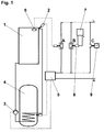
- a solar thermal system consists essentially of a solar collector 1, a temperature sensor 2, a pump 3 for a heat transfer medium in a heat transfer circuit through a heat exchanger in a hot water tank. 4
- a controller 5 can be switched off with different measures variants at night and in times without significant solar yield and only turned on when there is sufficient solar yield or is expected.
- a button thermostat 6 is provided on the glass surface of the solar collector 1, which turns on the control device 5 when a definable temperature threshold is exceeded and this falls below it.
- Variant B provides an additional, independent of the regulated solar system photovoltaic cell 7, which generates power for switching a relay 8, with the control device is switched on with sufficient power production and otherwise off.
- an additional, independent of the controlled solar system timer 9 is provided with low power consumption, with the control device 5 time-dependent on or off.
- a photovoltaic system consists essentially of a photovoltaic module 10 for power generation and an inverter 11 for the power supply to the public grid.
- the inverter 11 is switched off during the night and in times without significant solar yield and only switched on when there is sufficient solar yield or is expected, in variant A by measuring the current generated by the photovoltaic module 10 and / or the voltage with a measuring device 12th This measured value is evaluated and used to switch a relay 13 for the mains voltage supply of the inverter 11. When a predeterminable voltage and / or current threshold value is exceeded, the inverter 11 is switched on and off switched off when this value is undershot.
- Variant B also provides an additional, independent of the regulated solar system timer 9 with low power consumption, with which the inverter 11 can be switched on or off time-dependent.
Landscapes
- Engineering & Computer Science (AREA)
- Chemical & Material Sciences (AREA)
- Sustainable Development (AREA)
- Sustainable Energy (AREA)
- Physics & Mathematics (AREA)
- Thermal Sciences (AREA)
- Life Sciences & Earth Sciences (AREA)
- Combustion & Propulsion (AREA)
- Mechanical Engineering (AREA)
- General Engineering & Computer Science (AREA)
- Photovoltaic Devices (AREA)
- Inverter Devices (AREA)
- Heat-Pump Type And Storage Water Heaters (AREA)
Applications Claiming Priority (1)
| Application Number | Priority Date | Filing Date | Title |
|---|---|---|---|
| DE102008011105A DE102008011105A1 (de) | 2008-02-26 | 2008-02-26 | Verfahren zum Betreiben einer Solaranlage |
Publications (2)
| Publication Number | Publication Date |
|---|---|
| EP2096363A2 true EP2096363A2 (fr) | 2009-09-02 |
| EP2096363A3 EP2096363A3 (fr) | 2014-08-06 |
Family
ID=40679866
Family Applications (1)
| Application Number | Title | Priority Date | Filing Date |
|---|---|---|---|
| EP09002231.0A Withdrawn EP2096363A3 (fr) | 2008-02-26 | 2009-02-18 | Procédé destiné à l'exploitation d'une installation solaire |
Country Status (2)
| Country | Link |
|---|---|
| EP (1) | EP2096363A3 (fr) |
| DE (1) | DE102008011105A1 (fr) |
Cited By (2)
| Publication number | Priority date | Publication date | Assignee | Title |
|---|---|---|---|---|
| CN102313376A (zh) * | 2011-10-24 | 2012-01-11 | 安徽郁金香新能源科技有限公司 | 控制太阳能热水系统辅助热源工作的装置和方法 |
| CN102563921A (zh) * | 2012-01-19 | 2012-07-11 | 浙江师范大学 | 一种太阳能热水器自动控制系统 |
Family Cites Families (5)
| Publication number | Priority date | Publication date | Assignee | Title |
|---|---|---|---|---|
| DE19738889A1 (de) * | 1997-09-05 | 1999-03-11 | Christiane Unterste | Solaranlage "AUTARK" |
| DE102004057288B4 (de) * | 2004-11-26 | 2011-04-28 | Resol-Elektronische Regelungen Gmbh | Solarregler mit flexiblen Zeitintervallen |
| DE102005044670B3 (de) * | 2005-09-19 | 2007-02-08 | Robert Bosch Gmbh | Solarregler und Verfahren zum Regeln einer Solarkollektoranlage |
| DE102006042888A1 (de) * | 2005-12-06 | 2007-06-14 | Deutsches Zentrum für Luft- und Raumfahrt e.V. | Vorrichtung und Verfahren zur technischen Nutzung von Sonnenenergie |
| EP1833155B1 (fr) * | 2006-03-07 | 2020-07-15 | Siemens Aktiengesellschaft | Onduleur et procédé de fonctionnement de l'onduleur |
-
2008
- 2008-02-26 DE DE102008011105A patent/DE102008011105A1/de not_active Ceased
-
2009
- 2009-02-18 EP EP09002231.0A patent/EP2096363A3/fr not_active Withdrawn
Non-Patent Citations (1)
| Title |
|---|
| None * |
Cited By (4)
| Publication number | Priority date | Publication date | Assignee | Title |
|---|---|---|---|---|
| CN102313376A (zh) * | 2011-10-24 | 2012-01-11 | 安徽郁金香新能源科技有限公司 | 控制太阳能热水系统辅助热源工作的装置和方法 |
| CN102313376B (zh) * | 2011-10-24 | 2014-07-16 | 安徽郁金香新能源科技有限公司 | 控制太阳能热水系统辅助热源工作的装置和方法 |
| CN102563921A (zh) * | 2012-01-19 | 2012-07-11 | 浙江师范大学 | 一种太阳能热水器自动控制系统 |
| CN102563921B (zh) * | 2012-01-19 | 2015-04-29 | 浙江师范大学 | 一种太阳能热水器自动控制系统 |
Also Published As
| Publication number | Publication date |
|---|---|
| DE102008011105A1 (de) | 2009-08-27 |
| EP2096363A3 (fr) | 2014-08-06 |
Similar Documents
| Publication | Publication Date | Title |
|---|---|---|
| EP3014194B1 (fr) | Dispositif pour la production d'eau chaude | |
| EP2610999A2 (fr) | Procédé et dispositif de consommation d'énergie électrique d'une installation raccordée à un réseau domestique pour générer une énergie électrique renouvelable | |
| DE19535752A1 (de) | Steuerverfahren und Anordnung für ein unabhängiges Energieversorgungssystem | |
| DE102007041842A1 (de) | Verfahren zum Betrieb einer Straßenleuchte mit Photovoltaikgenerator sowie entsprechende Straßenleuchte | |
| DE3447879A1 (de) | Verfahren zur durchfuehrung einer gekoppelten waerme- und krafterzeugung, insbesondere bei industriekraftwerken | |
| DE102019001566A1 (de) | Betriebs-Überwachungs-System für ein Solarmodul | |
| EP2224175B1 (fr) | Système de régulation pour la régulation d'installations thermiques solaires et procédé | |
| EP2096363A2 (fr) | Procédé destiné à l'exploitation d'une installation solaire | |
| DE2856018A1 (de) | Anordnung zur regelung der waermeverteilung in einem solarhaus | |
| WO2014001302A1 (fr) | Chauffe-eau et procédé permettant de faire fonctionner un chauffe-eau | |
| DE202009008151U1 (de) | Solarstromversorgung für einen Verkaufsautomaten | |
| DE202021002165U1 (de) | Waschmaschine mit Leistungsanpassung zur Eigenverbrauchsmaximierung bei lokaler regenerativer Stromerzeugung | |
| WO2001055577A2 (fr) | Procede et dispositif pour produire du courant et de la chaleur | |
| DE102016107627B4 (de) | Anordnung zur Warmwasser- und Heizungswasser- Erzeugung unter mindestens teilweiser Nutzung von regenerativer elektrischer Energie | |
| EP2048431A1 (fr) | Lampe solaire avec variateur | |
| EP1764563B1 (fr) | Régulateur solaire et méthode pour régler une installation de collecteurs solaires | |
| DE202021002540U1 (de) | Geschirrspülmaschine mit Leistungsanpassung zur Eigenverbrauchsmaximierung bei lokaler regenerativer Stromerzeugung | |
| EP0171014A1 (fr) | Procédé et dispositif d'amélioration du rendement d'une centrale thermique, basé sur la capacité de stockage thermique du système de chauffage à distance | |
| DE102017109858A1 (de) | Verfahren und Vorrichtung zur effektiven Energieausnutzung | |
| DE102015215635A1 (de) | Beleuchtungssystem mit Energiemanagementfunktion und Verfahren zu dessen Betrieb | |
| DE29814206U1 (de) | Solare Heiz- und Wasserversorgung | |
| EP2728704A2 (fr) | Système de régulateur de charge pour la commande et/ou la régulation d'énergie électrique et/ou d'énergie thermique provenant de sources renouvelables | |
| CN2350562Y (zh) | 水泵全自动控制器 | |
| CN106169880B (zh) | 一种组串式光伏逆变器的间歇工作控制方法 | |
| DE10130162C1 (de) | Nachladesteuerung für einen mit Sonnenenergie beheizten Warmwasserspeicher |
Legal Events
| Date | Code | Title | Description |
|---|---|---|---|
| PUAI | Public reference made under article 153(3) epc to a published international application that has entered the european phase |
Free format text: ORIGINAL CODE: 0009012 |
|
| AK | Designated contracting states |
Kind code of ref document: A2 Designated state(s): AT BE BG CH CY CZ DE DK EE ES FI FR GB GR HR HU IE IS IT LI LT LU LV MC MK MT NL NO PL PT RO SE SI SK TR |
|
| AX | Request for extension of the european patent |
Extension state: AL BA RS |
|
| PUAL | Search report despatched |
Free format text: ORIGINAL CODE: 0009013 |
|
| AK | Designated contracting states |
Kind code of ref document: A3 Designated state(s): AT BE BG CH CY CZ DE DK EE ES FI FR GB GR HR HU IE IS IT LI LT LU LV MC MK MT NL NO PL PT RO SE SI SK TR |
|
| AX | Request for extension of the european patent |
Extension state: AL BA RS |
|
| RIC1 | Information provided on ipc code assigned before grant |
Ipc: F24D 11/00 20060101ALI20140630BHEP Ipc: H02M 7/48 20070101ALI20140630BHEP Ipc: F24D 19/10 20060101AFI20140630BHEP Ipc: F24D 17/00 20060101ALI20140630BHEP |
|
| 17P | Request for examination filed |
Effective date: 20150206 |
|
| RBV | Designated contracting states (corrected) |
Designated state(s): AT BE BG CH CY CZ DE DK EE ES FI FR GB GR HR HU IE IS IT LI LT LU LV MC MK MT NL NO PL PT RO SE SI SK TR |
|
| AKX | Designation fees paid |
Designated state(s): AT BE BG CH CY CZ DE DK EE ES FI FR GB GR HR HU IE IS IT LI LT LU LV MC MK MT NL NO PL PT RO SE SI SK TR |
|
| AXX | Extension fees paid |
Extension state: AL Extension state: RS Extension state: BA |
|
| 17Q | First examination report despatched |
Effective date: 20160126 |
|
| GRAP | Despatch of communication of intention to grant a patent |
Free format text: ORIGINAL CODE: EPIDOSNIGR1 |
|
| INTG | Intention to grant announced |
Effective date: 20180508 |
|
| STAA | Information on the status of an ep patent application or granted ep patent |
Free format text: STATUS: THE APPLICATION IS DEEMED TO BE WITHDRAWN |
|
| 18D | Application deemed to be withdrawn |
Effective date: 20180919 |