EP2096377B1 - Appareil de refrigeration - Google Patents
Appareil de refrigeration Download PDFInfo
- Publication number
- EP2096377B1 EP2096377B1 EP07850386.9A EP07850386A EP2096377B1 EP 2096377 B1 EP2096377 B1 EP 2096377B1 EP 07850386 A EP07850386 A EP 07850386A EP 2096377 B1 EP2096377 B1 EP 2096377B1
- Authority
- EP
- European Patent Office
- Prior art keywords
- refrigerant
- pressure
- heat
- source
- quasi
- Prior art date
- Legal status (The legal status is an assumption and is not a legal conclusion. Google has not performed a legal analysis and makes no representation as to the accuracy of the status listed.)
- Active
Links
Images

Classifications
-
- F—MECHANICAL ENGINEERING; LIGHTING; HEATING; WEAPONS; BLASTING
- F25—REFRIGERATION OR COOLING; COMBINED HEATING AND REFRIGERATION SYSTEMS; HEAT PUMP SYSTEMS; MANUFACTURE OR STORAGE OF ICE; LIQUEFACTION SOLIDIFICATION OF GASES
- F25B—REFRIGERATION MACHINES, PLANTS OR SYSTEMS; COMBINED HEATING AND REFRIGERATION SYSTEMS; HEAT PUMP SYSTEMS
- F25B9/00—Compression machines, plants or systems, in which the refrigerant is air or other gas of low boiling point
- F25B9/002—Compression machines, plants or systems, in which the refrigerant is air or other gas of low boiling point characterised by the refrigerant
- F25B9/008—Compression machines, plants or systems, in which the refrigerant is air or other gas of low boiling point characterised by the refrigerant the refrigerant being carbon dioxide
-
- F—MECHANICAL ENGINEERING; LIGHTING; HEATING; WEAPONS; BLASTING
- F25—REFRIGERATION OR COOLING; COMBINED HEATING AND REFRIGERATION SYSTEMS; HEAT PUMP SYSTEMS; MANUFACTURE OR STORAGE OF ICE; LIQUEFACTION SOLIDIFICATION OF GASES
- F25B—REFRIGERATION MACHINES, PLANTS OR SYSTEMS; COMBINED HEATING AND REFRIGERATION SYSTEMS; HEAT PUMP SYSTEMS
- F25B2309/00—Gas cycle refrigeration machines
- F25B2309/06—Compression machines, plants or systems characterised by the refrigerant being carbon dioxide
- F25B2309/061—Compression machines, plants or systems characterised by the refrigerant being carbon dioxide with cycle highest pressure above the supercritical pressure
-
- F—MECHANICAL ENGINEERING; LIGHTING; HEATING; WEAPONS; BLASTING
- F25—REFRIGERATION OR COOLING; COMBINED HEATING AND REFRIGERATION SYSTEMS; HEAT PUMP SYSTEMS; MANUFACTURE OR STORAGE OF ICE; LIQUEFACTION SOLIDIFICATION OF GASES
- F25B—REFRIGERATION MACHINES, PLANTS OR SYSTEMS; COMBINED HEATING AND REFRIGERATION SYSTEMS; HEAT PUMP SYSTEMS
- F25B2500/00—Problems to be solved
- F25B2500/19—Calculation of parameters
-
- F—MECHANICAL ENGINEERING; LIGHTING; HEATING; WEAPONS; BLASTING
- F25—REFRIGERATION OR COOLING; COMBINED HEATING AND REFRIGERATION SYSTEMS; HEAT PUMP SYSTEMS; MANUFACTURE OR STORAGE OF ICE; LIQUEFACTION SOLIDIFICATION OF GASES
- F25B—REFRIGERATION MACHINES, PLANTS OR SYSTEMS; COMBINED HEATING AND REFRIGERATION SYSTEMS; HEAT PUMP SYSTEMS
- F25B2600/00—Control issues
- F25B2600/17—Control issues by controlling the pressure of the condenser
-
- F—MECHANICAL ENGINEERING; LIGHTING; HEATING; WEAPONS; BLASTING
- F25—REFRIGERATION OR COOLING; COMBINED HEATING AND REFRIGERATION SYSTEMS; HEAT PUMP SYSTEMS; MANUFACTURE OR STORAGE OF ICE; LIQUEFACTION SOLIDIFICATION OF GASES
- F25B—REFRIGERATION MACHINES, PLANTS OR SYSTEMS; COMBINED HEATING AND REFRIGERATION SYSTEMS; HEAT PUMP SYSTEMS
- F25B2600/00—Control issues
- F25B2600/19—Refrigerant outlet condenser temperature
-
- F—MECHANICAL ENGINEERING; LIGHTING; HEATING; WEAPONS; BLASTING
- F25—REFRIGERATION OR COOLING; COMBINED HEATING AND REFRIGERATION SYSTEMS; HEAT PUMP SYSTEMS; MANUFACTURE OR STORAGE OF ICE; LIQUEFACTION SOLIDIFICATION OF GASES
- F25B—REFRIGERATION MACHINES, PLANTS OR SYSTEMS; COMBINED HEATING AND REFRIGERATION SYSTEMS; HEAT PUMP SYSTEMS
- F25B2700/00—Sensing or detecting of parameters; Sensors therefor
- F25B2700/21—Temperatures
- F25B2700/2102—Temperatures at the outlet of the gas cooler
Definitions
- the present invention relates to a refrigeration apparatus, and particularly relates to a refrigeration apparatus that performs a refrigeration cycle operation in which the high-pressure side attains a pressure that exceeds the critical pressure of the refrigerant.
- the use of a natural refrigerant that has minimal effect on the environment as the refrigerant charged in the refrigerant circuit has recently been studied.
- carbon dioxide or another refrigerant having a low critical temperature is used as the natural refrigerant, a refrigeration cycle operation is performed in which the refrigerant pressure on the high-pressure side exceeds the critical pressure of the refrigerant.
- the refrigerant pressure range on the high-pressure side whose coefficient of performance is near maximum is prescribed as the set value of the refrigerant pressure on the high-pressure side with respect to the refrigerant temperature at the outlet of a cooler, and the degree of opening or the like of a pressure reducing means is controlled so that the refrigerant pressure on the high-pressure side conforms to the set value (see Patent Document 1).
- the degree of opening or the like of the pressure reducing means when the degree of opening or the like of the pressure reducing means is controlled so that the refrigerant pressure on the high-pressure side conforms to the set value in the control method described above for controlling the refrigerant pressure on the high-pressure side, the refrigerant temperature at the outlet of the cooler changes, and this change is accompanied by a change in the refrigerant pressure range on the high-pressure side where the coefficient of performance is near maximum.
- the degree of opening or the like of the pressure reducing means must therefore be repeatedly controlled so that the refrigerant pressure reaches the set value of the refrigerant pressure on the high-pressure side after the change in the refrigerant temperature at the outlet of the cooler.
- US2002/007943 discloses a refrigeration apparatus according to the preamble of claim 1.
- An object of the present invention is to enable high-efficiency operation to be rapidly achieved in a refrigeration apparatus that performs a refrigeration cycle operation in which the high-pressure side attains a pressure that exceeds the critical temperature of the refrigerant.
- a refrigeration apparatus is a refrigeration apparatus having the features of claim 1.
- the inventors discovered a correlation between the coefficient of performance and the quasi-subcooling degree.
- a control method is therefore employed in the refrigeration apparatus for using such information to control the quasi-subcooling degree as a controlled variable so as to have a value within a predetermined temperature range.
- the convergence of control can thereby be enhanced in comparison to the conventional control method in which the refrigerant pressure on the high-pressure side with respect to the cooler outlet refrigerant temperature is controlled so as to conform to a set value.
- High-efficiency operation can therefore be rapidly achieved when the predetermined temperature range of the quasi-subcooling degree is set to a temperature range in which the coefficient of performance is near maximum.
- a refrigeration apparatus is the refrigeration apparatus according to the first aspect of the present invention, wherein the predetermined temperature range is set within a temperature range of 5°C to 12°C.
- the inventors discovered that the coefficient of performance is near maximum when the quasi-subcooling degree is within a temperature range of 5°C to 12°C. Such information is therefore used to achieve high-efficiency operation in which the coefficient of performance is near maximum in the refrigeration apparatus by setting the predetermined temperature range of the quasi-subcooling degree to within the temperature range of 5°C to 12°C.
- a refrigeration apparatus is the refrigeration apparatus according to the first or second aspect of the present invention, wherein the expansion mechanism is used as the constituent component.
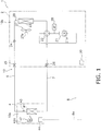
- FIG. 1 is a schematic configuration diagram showing an air conditioning apparatus 1 as an embodiment of the refrigeration apparatus of the present invention.
- the air conditioning apparatus 1 is a apparatus used for indoor cooling and heating by performing a vapor-compression refrigeration cycle operation.
- the air conditioning apparatus 1 in the present embodiment is provided with a heat source unit 2, a utilization unit 4, and a first refrigerant communication pipe 6 and a second refrigerant communication pipe 7 as refrigerant communication pipes for connecting the heat source unit 2 and the utilization unit 4.
- the vapor-compression refrigerant circuit 10 of the air conditioning apparatus 1 of the present embodiment is configured by the connection between the heat source unit 2, the utilization unit 4, and the refrigerant communication pipes 6, 7.
- Carbon dioxide as the refrigerant is charged into the refrigerant circuit 10, and as described hereinafter, a refrigeration cycle operation is performed in which the refrigerant is compressed to a pressure that exceeds the critical pressure of the refrigerant, and the refrigerant is cooled, reduced in pressure, and heated/evaporated, and then re-compressed.
- the utilization unit 4 is installed inside a room or the like and connected to the heat source unit 2 via the refrigerant communication pipes 6, 7, and constitutes a portion of the refrigerant circuit 10.
- the structure of the utilization unit 4 will next be described.
- the utilization unit 4 primarily has a utilization-side refrigerant circuit 10a that constitutes a portion of the refrigerant circuit 10.
- the utilization-side refrigerant circuit 10a primarily has a utilization-side heat exchanger 41.
- the utilization-side heat exchanger 41 is a heat exchanger that functions as a heater or a cooler of the refrigerant. One end of the utilization-side heat exchanger 41 is connected to the first refrigerant communication pipe 6, and the other end is connected to the second refrigerant communication pipe 7.
- the utilization unit 4 in the present embodiment is provided with a utilization-side fan 42 for sucking indoor air into the unit and supplying the air back into the room, and is capable of exchanging heat between the indoor air and the refrigerant that flows through the utilization-side heat exchanger 41.
- the utilization-side fan 42 is rotationally driven by a utilization-side fan driving motor 42a.
- a utilization-side heat exchanger temperature sensor 43 for detecting a cooler outlet refrigerant temperature Tco is provided to the outlet of the utilization-side heat exchanger 41 in a case in which the utilization-side heat exchanger 41 is made to function as a cooler of the refrigerant.
- the utilization-side heat exchanger temperature sensor 43 is composed of a thermistor.
- the utilization unit 4 also has a utilization-side control unit 44 for controlling the operation of the constituent components that constitute the utilization unit 4.
- the utilization-side control unit 44 has a microcomputer, memory, and other components provided in order to control the utilization unit 4, and is configured so as to be able to exchange control signals and the like with a remote controller (not shown) for separately operating the utilization unit 4, and exchange control signals and the like with the heat source unit 2 via a transmission line 8a.
- the heat source unit 2 is installed outside the room or elsewhere, is connected to the utilization unit 4 via the refrigerant communication pipes 6, 7, and forms the refrigerant circuit 10 with the utilization unit 4.
- the heat source unit 2 primarily has a heat-source-side refrigeration circuit 10b that constitutes a portion of the refrigerant circuit 10.
- the heat-source-side refrigeration circuit 10b primarily has a compressor 21, a switching mechanism 22, a heat-source-side heat exchanger 23, a heat-source-side expansion mechanism 24, a first closing valve 25, and a second closing valve 26.
- the compressor 21 in the present embodiment is a sealed compressor that is driven by a compressor driving motor 21 a.
- the switching mechanism 22 is a mechanism for switching the flow direction of refrigerant in the refrigerant circuit 10.
- the switching mechanism 22 is capable of connecting the discharge side of the compressor 21 and one end of the heat-source-side heat exchanger 23, and connecting the second closing valve 26 and the intake side of the compressor 21 (see the solid line of the switching mechanism 22 in FIG. 1 ) in order to cause the heat-source-side heat exchanger 23 to function as a cooler of the refrigerant compressed by the compressor 21, and to cause the utilization-side heat exchanger 41 to function as a heater of the refrigerant cooled in the heat-source-side heat exchanger 23.
- the switching mechanism 22 is capable of connecting the second closing valve 26 and the discharge side of the compressor 21, and connecting the intake side of the compressor 21 and one end of the heat-source-side heat exchanger 23 (see the dashed line of the switching mechanism 22 in FIG. 1 ) in order to cause the utilization-side heat exchanger 41 to function as a cooler of the refrigerant compressed by the compressor 21, and to cause the heat-source-side heat exchanger 23 to function as a heater of the refrigerant cooled in the utilization-side heat exchanger 41.
- the switching mechanism 22 is a four-way switch valve that is connected to the intake side of the compressor 21, the discharge side of the compressor 21, the heat-source-side heat exchanger 23 and the second closing valve 26.
- the switching mechanism 22 is not limited to a four-way switch valve, and may be configured so as to be capable of switching the direction of refrigerant flow in the same manner as described above by employing a configuration such as combining a plurality of magnetic valves, for example.
- the heat-source-side heat exchanger 23 is a heat exchanger for functioning as a cooler or a heater of the refrigerant. One end of the heat-source-side heat exchanger 23 is connected to the switching mechanism 22, and the other end is connected to the heat-source-side expansion mechanism 24.
- the heat source unit 2 has a heat-source-side fan 27 for sucking outside air into the unit and exhausting air back to the outside.
- the heat-source-side fan 27 is capable of exchanging heat between the outside air and the refrigerant that flows through the heat-source-side heat exchanger 23.
- the heat-source-side fan 27 is rotationally driven by a heat-source-side fan driving motor 27a.
- the heat source of the heat-source-side heat exchanger 23 is not limited to outside air and may be water or another heat medium.
- the heat-source-side expansion mechanism 24 is a mechanism for reducing the pressure of the refrigerant, and in the present embodiment, the heat-source-side expansion mechanism 24 is an electric expansion valve connected to the other end of the heat-source-side heat exchanger 23 for performing adjustment and the like of the flow rate of the refrigerant flowing in the heat-source-side refrigeration circuit 10b.
- One end of the heat-source-side expansion mechanism 24 is connected to the heat-source-side heat exchanger 23, and the other end is connected to the first closing valve 25.
- the first closing valve 25 is a valve to which the first refrigerant communication pipe 6 is connected for exchanging refrigerant between the heat source unit 2 and the utilization unit 4, and the first closing valve 25 is connected to the heat-source-side expansion mechanism 24.
- the second closing valve 26 is a valve to which the second refrigerant communication pipe 7 is connected for exchanging refrigerant between the heat source unit 2 and the utilization unit 4, and the second closing valve 26 is connected to the switching mechanism 22.
- the first and second closing valves 25, 26 are three-way valves provided with a service port that can be communicated with the outside of the refrigerant circuit 10.
- a compressor discharge pressure sensor 28 for detecting a compressor discharge pressure Pd is provided to the discharge side of the compressor 21, and a heat-source-side heat exchanger temperature sensor 29 for detecting the cooler outlet refrigerant temperature Tco is provided to the outlet of the heat-source-side heat exchanger 23 in a case in which the heat-source-side heat exchanger 23 is made to function as a cooler of the refrigerant.
- the heat-source-side heat exchanger temperature sensor 29 is composed of a thermistor.
- the heat source unit 2 also has a heat-source-side control unit 30 for controlling the operation of the constituent components that constitute the heat source unit 2.
- the heat-source-side control unit 30 has a microcomputer, memory, and the like provided in order to control the heat source unit 2, and is configured so as to be capable of exchanging control signals and the like with the utilization-side control unit 44 of the utilization- unit 4 via the transmission line 8a.
- the refrigerant communication pipes 6, 7 are refrigerant pipes that are constructed on-site when the air conditioning apparatus 1 is installed in the installation location thereof.
- the utilization-side refrigerant circuit 10a, the heat-source-side refrigeration circuit 10b, and the refrigerant communication pipes 6, 7 are connected as described above to form the refrigerant circuit 10.
- a control unit 8 as a control means for controlling the various operations of the air conditioning apparatus 1 is formed by the utilization-side control unit 44, the heat-source-side control unit 30, and the transmission line 8a for forming a connection between the control units 30, 44.
- the control unit 8 is capable of receiving the detection signals and the like of the various sensors 29, 30, 43 and can control the various constituent components 21, 22, 24, 27, 42 on the basis of the detection signals and the like.
- FIG. 2 is a pressure-enthalpy diagram showing the refrigeration cycle in the present embodiment.
- the switching mechanism 22 is in the state indicated by the solid line in FIG. 1 ; i.e., the switching mechanism 22 is in a state in which the discharge side of the compressor 21 is connected to the heat-source-side heat exchanger 23, and the intake side of the compressor 21 is connected to the second closing valve 26.
- the heat-source-side expansion mechanism 24 is configured so that the degree of opening thereof is adjusted.
- the closing valves 25, 26 are open.
- the low-pressure refrigerant (see point A of FIG. 2 ) is sucked into the compressor 21 and compressed to a pressure that exceeds the critical pressure (i.e., Pcp in FIG. 2 ), and becomes high-pressure refrigerant (see point B of FIG. 2 ).
- the high-pressure refrigerant is then sent through the switching mechanism 22 to the heat-source-side heat exchanger 23 that functions as a cooler of the refrigerant, the high-pressure refrigerant is caused to exchange heat with the outside air supplied by the heat-source-side fan 27, and the refrigerant is cooled (see point C of FIG. 2 ).
- the high-pressure refrigerant cooled in the heat-source-side heat exchanger 23 is then reduced in pressure by the heat-source-side expansion mechanism 24 and become low-pressure refrigerant in a gas/liquid two-phase state (see point D in FIG. 2 ), and is sent through the first closing valve 25 and the first refrigerant communication pipe 6 to the utilization unit 4.
- This low-pressure refrigerant in a gas/liquid two-phase state that is sent to the utilization unit 4 is caused to exchange heat with indoor air and heated in the utilization-side heat exchanger 41 that functions as a heater of the refrigerant, and the refrigerant is thereby evaporated to become low-pressure refrigerant (see point A of FIG. 2 ).
- the low-pressure refrigerant heated in the utilization-side heat exchanger 41 is then sent through the second refrigerant communication pipe 7 to the heat source unit 2 and again sucked back into the compressor 21 through the second closing valve 26 and the switching mechanism 22. Cooling is thus performed.
- a quasi-subcooling degree is controlled using the heat-source-side expansion mechanism 24.
- the degree of opening of the heat-source-side expansion mechanism 24 is adjusted so that the quasi-subcooling degree ⁇ Tqsc, which is the temperature difference between a quasi-condensation temperature Tqc and the refrigerant temperature (i.e., the cooler outlet refrigerant temperature Tco detected by the heat-source-side heat exchanger temperature sensor 29) at the outlet of the heat-source-side heat exchanger 23, is within a predetermined temperature range, the quasi-condensation temperature Tqc being the refrigerant temperature at which the isobaric specific heat capacity of the refrigerant at the refrigerant pressure (herein, the compressor discharge pressure Pd detected by the compressor discharge pressure sensor 28, or a pressure calculated while taking into account the loss in pressure from the discharge side of the compressor 21 to the heat-source-side heat exchanger 23 on the basis of the compressor discharge pressure Pd) on the high
- FIG. 3 is a diagram showing the relationship between the quasi-subcooling degree ⁇ Tqsc and the coefficient of performance.
- the degree of opening of the heat-source-side expansion mechanism 24 must therefore be repeatedly controlled so that the refrigerant pressure reaches the set value of the refrigerant pressure on the high-pressure side after the change in the cooler outlet refrigerant temperature Tco, and it takes time for the coefficient of performance to approach the maximum value.
- the inventors therefore investigated the range of refrigerant pressures on the high-pressure side with respect to the cooler outlet refrigerant temperature Tco, as well as controlled variables in the refrigeration cycle that are related to the coefficient of performance, and discovered that a correlation exists between the coefficient of performance and the quasi-subcooling degree ⁇ Tqsc, as shown in FIG. 3 .
- the inventors discovered that when a refrigeration cycle operation is performed in which the refrigerant pressure on the high-pressure side exceeds the critical pressure Pcp, the coefficient of performance hovers near the maximum thereof when the quasi-subcooling degree ⁇ Tqsc, which is the degree of cooling from the quasi-condensation temperature Tqc, is kept within a predetermined temperature range, the quasi-condensation temperature Tqc being the refrigerant temperature at which the isobaric specific heat capacity of the refrigerant is at a maximum (see the dotted line passing through point E and the critical point Tcp in FIG. 2 ).
- the predetermined temperature range of the quasi-subcooling degree ⁇ Tqsc is preferably a temperature range of 5°C to 12°C, as shown in FIG. 3 .
- a control method is therefore employed in the refrigeration apparatus 1 of the present embodiment for using such information to control the quasi-subcooling degree ⁇ Tqsc as a controlled variable so as to have a value within the predetermined temperature range.
- the convergence of control can thereby be enhanced in comparison to the conventional control method in which the refrigerant pressure on the high-pressure side with respect to the cooler outlet refrigerant temperature Tco is controlled so as to conform to a set value.
- High-efficiency operation can therefore be rapidly achieved when the predetermined temperature range of the quasi-subcooling degree ⁇ Tqsc is set to a temperature range in which the coefficient of performance is near maximum.
- the quasi-subcooling degree is controlled using the heat-source-side expansion mechanism 24, and when the quasi-subcooling degree ⁇ Tqsc is smaller than the minimum value (e.g., 5°C) of the predetermined temperature range, the degree of opening of the heat-source-side expansion mechanism 24 is controllably reduced, and when the quasi-subcooling degree ⁇ Tqsc is larger than the maximum value (e.g., 12°C) of the predetermined temperature range, the degree of opening of the heat-source-side expansion mechanism 24 is controllably increased. Satisfactory responsiveness of control is therefore obtained.
- the switching mechanism 22 is in the state indicated by the dashed line in FIG. 1 ; i.e., the switching mechanism 22 is in a state in which the discharge side of the compressor 21 is connected to the second closing valve 26, and the intake side of the compressor 21 is connected to the heat-source-side heat exchanger 23.
- the heat-source-side expansion mechanism 24 is configured so that the degree of opening thereof is adjusted.
- the closing valves 25, 26 are open.
- the high-pressure refrigerant sent to the utilization unit 4 is caused to exchange heat with indoor air and cooled in the utilization-side heat exchanger 41 that functions as a cooler of the refrigerant (see point C of FIG. 2 ), and is then sent through the first refrigerant communication pipe 6 to the heat source unit 2.
- the high-pressure refrigerant sent to the heat source unit 2 is reduced in pressure by the heat-source-side expansion mechanism 24 and become low-pressure refrigerant in a gas/liquid two-phase state (see point D of FIG. 2 ), and flows into the heat-source-side heat exchanger 23 that functions as a heater of the refrigerant.
- the low-pressure refrigerant in a gas/liquid two-phase state that has flowed into the heat-source-side heat exchanger 23 is then evaporated and become low-pressure refrigerant by being heat-exchanged with outside air supplied by the heat-source-side fan 27 and by being heated by the outside air (see point A of FIG. 2 ), and the refrigerant is again sucked back into the compressor 21 through the switching mechanism 22. Heating is thereby performed.
- the quasi-subcooling degree is controlled using the heat-source-side expansion mechanism 24.
- This control of the quasi-subcooling degree during heating differs from control during cooling, in that the temperature difference between the quasi-condensation temperature Tqc and the refrigerant temperature at the outlet of the utilization-side heat exchanger 41 (i.e., the cooler outlet refrigerant temperature Tco detected by the utilization-side heat exchanger temperature sensor 43) is the quasi-subcooling degree ⁇ Tqsc, but substantially the same control can be performed as during cooling. High-efficiency operation can thereby be rapidly achieved in the same manner as during cooling.
- the control unit 8 (more specifically, the utilization-side control unit 44, the heat-source-side control unit 30, and the transmission line 8a for connecting the control units 30, 44) for functioning as an operation control means controls operation in cooling and heating, including controlling the quasi-subcooling degree.
- high-efficiency operation can be rapidly achieved in a refrigeration apparatus that performs a refrigeration cycle operation in which the high-pressure side attains a pressure that exceeds the critical pressure.
Landscapes
- Engineering & Computer Science (AREA)
- Chemical & Material Sciences (AREA)
- Chemical Kinetics & Catalysis (AREA)
- Physics & Mathematics (AREA)
- Mechanical Engineering (AREA)
- Thermal Sciences (AREA)
- General Engineering & Computer Science (AREA)
- Air Conditioning Control Device (AREA)
Claims (4)
- Appareil de réfrigération (1) pour la réalisation d'une opération de cycle de réfrigération dans laquelle un côté haute pression atteint une pression qui dépasse la pression critique d'un fluide frigorigène, l'appareil de réfrigération ayant un circuit de fluide frigorigène (10) qui comprend un compresseur (21), un refroidisseur (23, 41), un mécanisme de détente (24), et un réchauffeur (41, 23),
et une unité de commande (8) pour commander le fonctionnement de l'appareil de réfrigération (1), caractérisé en ce que l'unité de commande est formée par une unité de commande côté utilisation (44), une unité de commande côté source de chaleur (30) et une ligne de transmission (8a) pour former une connexion entre l'unité de commande côté utilisation (44) et l'unité de commande côté source de chaleur (30),
dans lequel l'unité de commande (8) est configurée pour commander un composant constitutif (21, 22, 24, 27, 42) de sorte qu'un degré de quasi-sous-refroidissement (ΔTqsc), qui est la différence de température entre une température de quasi-condensation (Tqc) et une température de fluide frigorigène de sortie de refroidisseur (Tco), soit dans une plage de températures prédéterminée, la température de quasi-condensation étant la température de fluide frigorigène à laquelle la capacité thermique isobarique spécifique du fluide frigorigène à la pression de fluide frigorigène du côté haute pression du cycle de réfrigération est à un maximum. - Appareil de réfrigération (1) selon la revendication 1, dans lequel la plage de températures prédéterminée est définie dans une plage de températures de 5 à 12 °C.
- Appareil de réfrigération (1) selon la revendication 1 ou 2, dans lequel le mécanisme de détente (24) est utilisé en tant que le composant constitutif.
- Procédé de commande d'un appareil de réfrigération (1) selon la revendication 1,
caractérisé en ce que
un composant constitutif est commandé de sorte qu'un degré de quasi-sous-refroidissement (ΔTqsc), qui est la différence de température entre une température de quasi-condensation (Tqc) et une température de fluide frigorigène de sortie de refroidisseur (Tco), soit dans une plage de températures prédéterminée, la température de quasi-condensation étant la température de fluide frigorigène à laquelle la capacité thermique isobarique spécifique du fluide frigorigène à la pression de fluide frigorigène du côté haute pression du cycle de réfrigération est à un maximum.
Applications Claiming Priority (2)
| Application Number | Priority Date | Filing Date | Title |
|---|---|---|---|
| JP2006334042A JP4245044B2 (ja) | 2006-12-12 | 2006-12-12 | 冷凍装置 |
| PCT/JP2007/073820 WO2008072608A1 (fr) | 2006-12-12 | 2007-12-11 | Dispositif de congélation |
Publications (3)
| Publication Number | Publication Date |
|---|---|
| EP2096377A1 EP2096377A1 (fr) | 2009-09-02 |
| EP2096377A4 EP2096377A4 (fr) | 2012-05-30 |
| EP2096377B1 true EP2096377B1 (fr) | 2017-02-01 |
Family
ID=39511629
Family Applications (1)
| Application Number | Title | Priority Date | Filing Date |
|---|---|---|---|
| EP07850386.9A Active EP2096377B1 (fr) | 2006-12-12 | 2007-12-11 | Appareil de refrigeration |
Country Status (6)
| Country | Link |
|---|---|
| US (1) | US7921670B2 (fr) |
| EP (1) | EP2096377B1 (fr) |
| JP (1) | JP4245044B2 (fr) |
| CN (2) | CN101558267B (fr) |
| ES (1) | ES2621156T3 (fr) |
| WO (1) | WO2008072608A1 (fr) |
Families Citing this family (6)
| Publication number | Priority date | Publication date | Assignee | Title |
|---|---|---|---|---|
| JP5046895B2 (ja) * | 2007-12-06 | 2012-10-10 | 三菱電機株式会社 | 空気調和装置およびその運転制御方法 |
| JP5330074B2 (ja) * | 2009-04-24 | 2013-10-30 | パナソニック株式会社 | 床暖房パネル |
| JP2011069570A (ja) * | 2009-09-28 | 2011-04-07 | Fujitsu General Ltd | ヒートポンプサイクル装置 |
| US8959940B2 (en) | 2010-02-12 | 2015-02-24 | Mitsubishi Electric Corporation | Refrigeration cycle apparatus |
| CN108917133A (zh) * | 2018-07-27 | 2018-11-30 | 奥克斯空调股份有限公司 | 风机转速匹配方法、装置及空调器 |
| CN112833522A (zh) * | 2019-11-22 | 2021-05-25 | 三花控股集团有限公司 | 一种控制系统及其控制方法 |
Family Cites Families (23)
| Publication number | Priority date | Publication date | Assignee | Title |
|---|---|---|---|---|
| JP3334507B2 (ja) * | 1996-09-13 | 2002-10-15 | 三菱電機株式会社 | 冷凍システム装置および冷凍システム装置の制御方法 |
| US6321564B1 (en) * | 1999-03-15 | 2001-11-27 | Denso Corporation | Refrigerant cycle system with expansion energy recovery |
| JP2001248920A (ja) * | 2000-03-06 | 2001-09-14 | Mitsubishi Electric Corp | 冷凍回路の制御装置 |
| JP2001289537A (ja) * | 2000-04-10 | 2001-10-19 | Mitsubishi Heavy Ind Ltd | 圧力制御弁 |
| US6430949B2 (en) * | 2000-04-19 | 2002-08-13 | Denso Corporation | Heat-pump water heater |
| JP4517529B2 (ja) * | 2000-07-21 | 2010-08-04 | 株式会社日本自動車部品総合研究所 | ヒートポンプサイクル、加熱装置、車両用暖房装置、暖房装置および蒸気圧縮式冷凍サイクル |
| JP3679323B2 (ja) * | 2000-10-30 | 2005-08-03 | 三菱電機株式会社 | 冷凍サイクル装置およびその制御方法 |
| JP4492017B2 (ja) * | 2000-11-09 | 2010-06-30 | 株式会社デンソー | アキュムレータモジュール |
| US6871511B2 (en) * | 2001-02-21 | 2005-03-29 | Matsushita Electric Industrial Co., Ltd. | Refrigeration-cycle equipment |
| NO320664B1 (no) * | 2001-12-19 | 2006-01-16 | Sinvent As | System for oppvarming og kjoling av kjoretoy |
| KR100567491B1 (ko) * | 2002-02-12 | 2006-04-03 | 마츠시타 덴끼 산교 가부시키가이샤 | 히트 펌프 급탕 장치 |
| JP2004162945A (ja) | 2002-11-11 | 2004-06-10 | Mitsubishi Electric Corp | 空気調和装置 |
| NO318864B1 (no) * | 2002-12-23 | 2005-05-18 | Sinvent As | Forbedret varmepumpesystem |
| JP4232463B2 (ja) * | 2003-01-09 | 2009-03-04 | 株式会社デンソー | 空調装置 |
| SE525022C2 (sv) * | 2003-04-17 | 2004-11-09 | Ep Technology Ab | Förångare och värmeväxlare med extern slinga |
| US7127905B2 (en) * | 2003-12-19 | 2006-10-31 | Carrier Corporation | Vapor compression system startup method |
| US7716943B2 (en) * | 2004-05-12 | 2010-05-18 | Electro Industries, Inc. | Heating/cooling system |
| JP4179231B2 (ja) * | 2004-06-09 | 2008-11-12 | 株式会社デンソー | 圧力制御弁と蒸気圧縮式冷凍サイクル |
| JP4118254B2 (ja) * | 2004-06-18 | 2008-07-16 | 三洋電機株式会社 | 冷凍装置 |
| JP4613526B2 (ja) * | 2004-06-23 | 2011-01-19 | 株式会社デンソー | 超臨界式ヒートポンプサイクル装置 |
| JP4581720B2 (ja) * | 2004-09-29 | 2010-11-17 | 株式会社デンソー | エジェクタを用いたサイクル |
| JP4415835B2 (ja) * | 2004-11-24 | 2010-02-17 | 株式会社デンソー | 車両用冷凍サイクル装置 |
| ES2728954T3 (es) * | 2005-10-25 | 2019-10-29 | Mitsubishi Electric Corp | Aparato acondicionador de aire, método de llenado de refrigerante en aparato de acondicionador de aire, método para evaluar el estado de llenado de refrigerante en aparato de acondicionador de aire y método de llenado de refrigerante/limpieza de tuberías para aparato acondicionador de aire |
-
2006
- 2006-12-12 JP JP2006334042A patent/JP4245044B2/ja active Active
-
2007
- 2007-12-11 CN CN2007800458323A patent/CN101558267B/zh active Active
- 2007-12-11 ES ES07850386.9T patent/ES2621156T3/es active Active
- 2007-12-11 CN CN2010102110667A patent/CN101858667B/zh active Active
- 2007-12-11 US US12/517,499 patent/US7921670B2/en active Active
- 2007-12-11 EP EP07850386.9A patent/EP2096377B1/fr active Active
- 2007-12-11 WO PCT/JP2007/073820 patent/WO2008072608A1/fr not_active Ceased
Non-Patent Citations (1)
| Title |
|---|
| None * |
Also Published As
| Publication number | Publication date |
|---|---|
| EP2096377A4 (fr) | 2012-05-30 |
| ES2621156T3 (es) | 2017-07-03 |
| CN101558267A (zh) | 2009-10-14 |
| CN101858667B (zh) | 2013-01-02 |
| JP4245044B2 (ja) | 2009-03-25 |
| WO2008072608A1 (fr) | 2008-06-19 |
| EP2096377A1 (fr) | 2009-09-02 |
| US7921670B2 (en) | 2011-04-12 |
| CN101858667A (zh) | 2010-10-13 |
| CN101558267B (zh) | 2010-12-01 |
| JP2008145066A (ja) | 2008-06-26 |
| US20100011805A1 (en) | 2010-01-21 |
Similar Documents
| Publication | Publication Date | Title |
|---|---|---|
| JP4931848B2 (ja) | ヒートポンプ式給湯用室外機 | |
| CN104024764B (zh) | 制冷装置 | |
| JP6479162B2 (ja) | 空気調和装置 | |
| EP3285021B1 (fr) | Dispositif de climatisation et d'alimentation en eau chaude de type pompe à chaleur | |
| JP5182358B2 (ja) | 冷凍装置 | |
| JP2008232508A (ja) | 給湯器 | |
| WO2007108319A1 (fr) | Appareil de réfrigération | |
| JP2005127687A (ja) | 空気調和機及びその制御方法 | |
| US7921670B2 (en) | Refrigeration apparatus | |
| JP4053082B2 (ja) | 冷凍サイクル装置 | |
| JP4273493B2 (ja) | 冷凍空調装置 | |
| CN100439824C (zh) | 空气调节装置 | |
| CN106931545A (zh) | 一种热泵喷焓系统及其控制方法、空调器 | |
| US20090044557A1 (en) | Vapor compression system | |
| WO2008069265A1 (fr) | Climatiseur | |
| EP2375187A2 (fr) | Appareil de pompe à chaleur et procédé de contrôle de fonctionnement de l'appareil de pompe à chaleur | |
| JP4386071B2 (ja) | 冷凍装置 | |
| JP2003106609A (ja) | 冷凍装置 | |
| CN106931546A (zh) | 一种热泵喷焓系统及其控制方法、空调器 | |
| KR100535687B1 (ko) | 멀티형 공기조화시스템 | |
| JP4830399B2 (ja) | 空気調和装置 | |
| JP3661014B2 (ja) | 冷凍装置 | |
| JP2003042585A (ja) | 空気調和機 | |
| US20250003615A1 (en) | Air-conditioning apparatus | |
| JP2005037003A (ja) | 空気調和機 |
Legal Events
| Date | Code | Title | Description |
|---|---|---|---|
| PUAI | Public reference made under article 153(3) epc to a published international application that has entered the european phase |
Free format text: ORIGINAL CODE: 0009012 |
|
| 17P | Request for examination filed |
Effective date: 20090630 |
|
| AK | Designated contracting states |
Kind code of ref document: A1 Designated state(s): AT BE BG CH CY CZ DE DK EE ES FI FR GB GR HU IE IS IT LI LT LU LV MC MT NL PL PT RO SE SI SK TR |
|
| DAX | Request for extension of the european patent (deleted) | ||
| A4 | Supplementary search report drawn up and despatched |
Effective date: 20120504 |
|
| RIC1 | Information provided on ipc code assigned before grant |
Ipc: F25B 9/00 20060101ALI20120426BHEP Ipc: F25B 1/00 20060101AFI20120426BHEP Ipc: F24F 11/02 20060101ALI20120426BHEP |
|
| 17Q | First examination report despatched |
Effective date: 20140212 |
|
| GRAP | Despatch of communication of intention to grant a patent |
Free format text: ORIGINAL CODE: EPIDOSNIGR1 |
|
| INTG | Intention to grant announced |
Effective date: 20160721 |
|
| GRAS | Grant fee paid |
Free format text: ORIGINAL CODE: EPIDOSNIGR3 |
|
| STAA | Information on the status of an ep patent application or granted ep patent |
Free format text: STATUS: GRANT OF PATENT IS INTENDED |
|
| RIN1 | Information on inventor provided before grant (corrected) |
Inventor name: UENO, YOSHIO |
|
| GRAA | (expected) grant |
Free format text: ORIGINAL CODE: 0009210 |
|
| STAA | Information on the status of an ep patent application or granted ep patent |
Free format text: STATUS: THE PATENT HAS BEEN GRANTED |
|
| AK | Designated contracting states |
Kind code of ref document: B1 Designated state(s): AT BE BG CH CY CZ DE DK EE ES FI FR GB GR HU IE IS IT LI LT LU LV MC MT NL PL PT RO SE SI SK TR |
|
| REG | Reference to a national code |
Ref country code: GB Ref legal event code: FG4D |
|
| REG | Reference to a national code |
Ref country code: CH Ref legal event code: EP Ref country code: AT Ref legal event code: REF Ref document number: 865929 Country of ref document: AT Kind code of ref document: T Effective date: 20170215 |
|
| REG | Reference to a national code |
Ref country code: IE Ref legal event code: FG4D |
|
| REG | Reference to a national code |
Ref country code: DE Ref legal event code: R096 Ref document number: 602007049733 Country of ref document: DE |
|
| REG | Reference to a national code |
Ref country code: NL Ref legal event code: MP Effective date: 20170201 |
|
| REG | Reference to a national code |
Ref country code: LT Ref legal event code: MG4D |
|
| REG | Reference to a national code |
Ref country code: AT Ref legal event code: MK05 Ref document number: 865929 Country of ref document: AT Kind code of ref document: T Effective date: 20170201 |
|
| REG | Reference to a national code |
Ref country code: ES Ref legal event code: FG2A Ref document number: 2621156 Country of ref document: ES Kind code of ref document: T3 Effective date: 20170703 |
|
| PG25 | Lapsed in a contracting state [announced via postgrant information from national office to epo] |
Ref country code: FI Free format text: LAPSE BECAUSE OF FAILURE TO SUBMIT A TRANSLATION OF THE DESCRIPTION OR TO PAY THE FEE WITHIN THE PRESCRIBED TIME-LIMIT Effective date: 20170201 Ref country code: GR Free format text: LAPSE BECAUSE OF FAILURE TO SUBMIT A TRANSLATION OF THE DESCRIPTION OR TO PAY THE FEE WITHIN THE PRESCRIBED TIME-LIMIT Effective date: 20170502 Ref country code: LT Free format text: LAPSE BECAUSE OF FAILURE TO SUBMIT A TRANSLATION OF THE DESCRIPTION OR TO PAY THE FEE WITHIN THE PRESCRIBED TIME-LIMIT Effective date: 20170201 Ref country code: IS Free format text: LAPSE BECAUSE OF FAILURE TO SUBMIT A TRANSLATION OF THE DESCRIPTION OR TO PAY THE FEE WITHIN THE PRESCRIBED TIME-LIMIT Effective date: 20170601 |
|
| PG25 | Lapsed in a contracting state [announced via postgrant information from national office to epo] |
Ref country code: PT Free format text: LAPSE BECAUSE OF FAILURE TO SUBMIT A TRANSLATION OF THE DESCRIPTION OR TO PAY THE FEE WITHIN THE PRESCRIBED TIME-LIMIT Effective date: 20170601 Ref country code: LV Free format text: LAPSE BECAUSE OF FAILURE TO SUBMIT A TRANSLATION OF THE DESCRIPTION OR TO PAY THE FEE WITHIN THE PRESCRIBED TIME-LIMIT Effective date: 20170201 Ref country code: SE Free format text: LAPSE BECAUSE OF FAILURE TO SUBMIT A TRANSLATION OF THE DESCRIPTION OR TO PAY THE FEE WITHIN THE PRESCRIBED TIME-LIMIT Effective date: 20170201 Ref country code: BG Free format text: LAPSE BECAUSE OF FAILURE TO SUBMIT A TRANSLATION OF THE DESCRIPTION OR TO PAY THE FEE WITHIN THE PRESCRIBED TIME-LIMIT Effective date: 20170501 Ref country code: PL Free format text: LAPSE BECAUSE OF FAILURE TO SUBMIT A TRANSLATION OF THE DESCRIPTION OR TO PAY THE FEE WITHIN THE PRESCRIBED TIME-LIMIT Effective date: 20170201 Ref country code: NL Free format text: LAPSE BECAUSE OF FAILURE TO SUBMIT A TRANSLATION OF THE DESCRIPTION OR TO PAY THE FEE WITHIN THE PRESCRIBED TIME-LIMIT Effective date: 20170201 Ref country code: AT Free format text: LAPSE BECAUSE OF FAILURE TO SUBMIT A TRANSLATION OF THE DESCRIPTION OR TO PAY THE FEE WITHIN THE PRESCRIBED TIME-LIMIT Effective date: 20170201 |
|
| PG25 | Lapsed in a contracting state [announced via postgrant information from national office to epo] |
Ref country code: CZ Free format text: LAPSE BECAUSE OF FAILURE TO SUBMIT A TRANSLATION OF THE DESCRIPTION OR TO PAY THE FEE WITHIN THE PRESCRIBED TIME-LIMIT Effective date: 20170201 Ref country code: EE Free format text: LAPSE BECAUSE OF FAILURE TO SUBMIT A TRANSLATION OF THE DESCRIPTION OR TO PAY THE FEE WITHIN THE PRESCRIBED TIME-LIMIT Effective date: 20170201 Ref country code: SK Free format text: LAPSE BECAUSE OF FAILURE TO SUBMIT A TRANSLATION OF THE DESCRIPTION OR TO PAY THE FEE WITHIN THE PRESCRIBED TIME-LIMIT Effective date: 20170201 Ref country code: RO Free format text: LAPSE BECAUSE OF FAILURE TO SUBMIT A TRANSLATION OF THE DESCRIPTION OR TO PAY THE FEE WITHIN THE PRESCRIBED TIME-LIMIT Effective date: 20170201 |
|
| REG | Reference to a national code |
Ref country code: DE Ref legal event code: R097 Ref document number: 602007049733 Country of ref document: DE |
|
| PG25 | Lapsed in a contracting state [announced via postgrant information from national office to epo] |
Ref country code: DK Free format text: LAPSE BECAUSE OF FAILURE TO SUBMIT A TRANSLATION OF THE DESCRIPTION OR TO PAY THE FEE WITHIN THE PRESCRIBED TIME-LIMIT Effective date: 20170201 |
|
| PLBE | No opposition filed within time limit |
Free format text: ORIGINAL CODE: 0009261 |
|
| STAA | Information on the status of an ep patent application or granted ep patent |
Free format text: STATUS: NO OPPOSITION FILED WITHIN TIME LIMIT |
|
| REG | Reference to a national code |
Ref country code: FR Ref legal event code: PLFP Year of fee payment: 11 |
|
| 26N | No opposition filed |
Effective date: 20171103 |
|
| PG25 | Lapsed in a contracting state [announced via postgrant information from national office to epo] |
Ref country code: SI Free format text: LAPSE BECAUSE OF FAILURE TO SUBMIT A TRANSLATION OF THE DESCRIPTION OR TO PAY THE FEE WITHIN THE PRESCRIBED TIME-LIMIT Effective date: 20170201 |
|
| REG | Reference to a national code |
Ref country code: CH Ref legal event code: PL |
|
| REG | Reference to a national code |
Ref country code: IE Ref legal event code: MM4A |
|
| PG25 | Lapsed in a contracting state [announced via postgrant information from national office to epo] |
Ref country code: LU Free format text: LAPSE BECAUSE OF NON-PAYMENT OF DUE FEES Effective date: 20171211 Ref country code: MT Free format text: LAPSE BECAUSE OF NON-PAYMENT OF DUE FEES Effective date: 20171211 |
|
| REG | Reference to a national code |
Ref country code: BE Ref legal event code: MM Effective date: 20171231 |
|
| PG25 | Lapsed in a contracting state [announced via postgrant information from national office to epo] |
Ref country code: IE Free format text: LAPSE BECAUSE OF NON-PAYMENT OF DUE FEES Effective date: 20171211 |
|
| PG25 | Lapsed in a contracting state [announced via postgrant information from national office to epo] |
Ref country code: CH Free format text: LAPSE BECAUSE OF NON-PAYMENT OF DUE FEES Effective date: 20171231 Ref country code: BE Free format text: LAPSE BECAUSE OF NON-PAYMENT OF DUE FEES Effective date: 20171231 Ref country code: LI Free format text: LAPSE BECAUSE OF NON-PAYMENT OF DUE FEES Effective date: 20171231 |
|
| PG25 | Lapsed in a contracting state [announced via postgrant information from national office to epo] |
Ref country code: HU Free format text: LAPSE BECAUSE OF FAILURE TO SUBMIT A TRANSLATION OF THE DESCRIPTION OR TO PAY THE FEE WITHIN THE PRESCRIBED TIME-LIMIT; INVALID AB INITIO Effective date: 20071211 Ref country code: MC Free format text: LAPSE BECAUSE OF FAILURE TO SUBMIT A TRANSLATION OF THE DESCRIPTION OR TO PAY THE FEE WITHIN THE PRESCRIBED TIME-LIMIT Effective date: 20170201 |
|
| PG25 | Lapsed in a contracting state [announced via postgrant information from national office to epo] |
Ref country code: CY Free format text: LAPSE BECAUSE OF NON-PAYMENT OF DUE FEES Effective date: 20170201 |
|
| PG25 | Lapsed in a contracting state [announced via postgrant information from national office to epo] |
Ref country code: TR Free format text: LAPSE BECAUSE OF FAILURE TO SUBMIT A TRANSLATION OF THE DESCRIPTION OR TO PAY THE FEE WITHIN THE PRESCRIBED TIME-LIMIT Effective date: 20170201 |
|
| P01 | Opt-out of the competence of the unified patent court (upc) registered |
Effective date: 20230525 |
|
| PGFP | Annual fee paid to national office [announced via postgrant information from national office to epo] |
Ref country code: DE Payment date: 20251028 Year of fee payment: 19 |
|
| PGFP | Annual fee paid to national office [announced via postgrant information from national office to epo] |
Ref country code: GB Payment date: 20251030 Year of fee payment: 19 |
|
| PGFP | Annual fee paid to national office [announced via postgrant information from national office to epo] |
Ref country code: IT Payment date: 20251121 Year of fee payment: 19 |
|
| PGFP | Annual fee paid to national office [announced via postgrant information from national office to epo] |
Ref country code: FR Payment date: 20251117 Year of fee payment: 19 |
|
| PGFP | Annual fee paid to national office [announced via postgrant information from national office to epo] |
Ref country code: ES Payment date: 20260108 Year of fee payment: 19 |