EP2096391A2 - Réfrigérateur et procédé pour son contrôle - Google Patents
Réfrigérateur et procédé pour son contrôle Download PDFInfo
- Publication number
- EP2096391A2 EP2096391A2 EP09153573A EP09153573A EP2096391A2 EP 2096391 A2 EP2096391 A2 EP 2096391A2 EP 09153573 A EP09153573 A EP 09153573A EP 09153573 A EP09153573 A EP 09153573A EP 2096391 A2 EP2096391 A2 EP 2096391A2
- Authority
- EP
- European Patent Office
- Prior art keywords
- home bar
- heater
- voltage
- refrigerator
- door
- Prior art date
- Legal status (The legal status is an assumption and is not a legal conclusion. Google has not performed a legal analysis and makes no representation as to the accuracy of the status listed.)
- Granted
Links
- 238000000034 method Methods 0.000 title claims abstract description 33
- 230000008859 change Effects 0.000 claims description 6
- 238000010438 heat treatment Methods 0.000 claims description 6
- 239000011810 insulating material Substances 0.000 claims description 4
- 230000008014 freezing Effects 0.000 description 13
- 238000007710 freezing Methods 0.000 description 13
- 239000004065 semiconductor Substances 0.000 description 5
- 230000006870 function Effects 0.000 description 4
- 230000002093 peripheral effect Effects 0.000 description 4
- 230000008569 process Effects 0.000 description 4
- 235000013305 food Nutrition 0.000 description 3
- 239000012774 insulation material Substances 0.000 description 3
- 238000012986 modification Methods 0.000 description 3
- 230000004048 modification Effects 0.000 description 3
- 230000005494 condensation Effects 0.000 description 1
- 238000009833 condensation Methods 0.000 description 1
- 230000003247 decreasing effect Effects 0.000 description 1
- 230000003111 delayed effect Effects 0.000 description 1
- 230000000694 effects Effects 0.000 description 1
- 238000009413 insulation Methods 0.000 description 1
Images



Classifications
-
- F—MECHANICAL ENGINEERING; LIGHTING; HEATING; WEAPONS; BLASTING
- F25—REFRIGERATION OR COOLING; COMBINED HEATING AND REFRIGERATION SYSTEMS; HEAT PUMP SYSTEMS; MANUFACTURE OR STORAGE OF ICE; LIQUEFACTION SOLIDIFICATION OF GASES
- F25D—REFRIGERATORS; COLD ROOMS; ICE-BOXES; COOLING OR FREEZING APPARATUS NOT OTHERWISE PROVIDED FOR
- F25D23/00—General constructional features
- F25D23/02—Doors; Covers
- F25D23/025—Secondary closures
-
- F—MECHANICAL ENGINEERING; LIGHTING; HEATING; WEAPONS; BLASTING
- F25—REFRIGERATION OR COOLING; COMBINED HEATING AND REFRIGERATION SYSTEMS; HEAT PUMP SYSTEMS; MANUFACTURE OR STORAGE OF ICE; LIQUEFACTION SOLIDIFICATION OF GASES
- F25D—REFRIGERATORS; COLD ROOMS; ICE-BOXES; COOLING OR FREEZING APPARATUS NOT OTHERWISE PROVIDED FOR
- F25D23/00—General constructional features
- F25D23/02—Doors; Covers
- F25D23/04—Doors; Covers with special compartments, e.g. butter conditioners
-
- F—MECHANICAL ENGINEERING; LIGHTING; HEATING; WEAPONS; BLASTING
- F25—REFRIGERATION OR COOLING; COMBINED HEATING AND REFRIGERATION SYSTEMS; HEAT PUMP SYSTEMS; MANUFACTURE OR STORAGE OF ICE; LIQUEFACTION SOLIDIFICATION OF GASES
- F25D—REFRIGERATORS; COLD ROOMS; ICE-BOXES; COOLING OR FREEZING APPARATUS NOT OTHERWISE PROVIDED FOR
- F25D2323/00—General constructional features not provided for in other groups of this subclass
- F25D2323/02—Details of doors or covers not otherwise covered
- F25D2323/023—Door in door constructions
-
- F—MECHANICAL ENGINEERING; LIGHTING; HEATING; WEAPONS; BLASTING
- F25—REFRIGERATION OR COOLING; COMBINED HEATING AND REFRIGERATION SYSTEMS; HEAT PUMP SYSTEMS; MANUFACTURE OR STORAGE OF ICE; LIQUEFACTION SOLIDIFICATION OF GASES
- F25D—REFRIGERATORS; COLD ROOMS; ICE-BOXES; COOLING OR FREEZING APPARATUS NOT OTHERWISE PROVIDED FOR
- F25D2400/00—General features of, or devices for refrigerators, cold rooms, ice-boxes, or for cooling or freezing apparatus not covered by any other subclass
- F25D2400/02—Refrigerators including a heater
-
- F—MECHANICAL ENGINEERING; LIGHTING; HEATING; WEAPONS; BLASTING
- F25—REFRIGERATION OR COOLING; COMBINED HEATING AND REFRIGERATION SYSTEMS; HEAT PUMP SYSTEMS; MANUFACTURE OR STORAGE OF ICE; LIQUEFACTION SOLIDIFICATION OF GASES
- F25D—REFRIGERATORS; COLD ROOMS; ICE-BOXES; COOLING OR FREEZING APPARATUS NOT OTHERWISE PROVIDED FOR
- F25D2400/00—General features of, or devices for refrigerators, cold rooms, ice-boxes, or for cooling or freezing apparatus not covered by any other subclass
- F25D2400/06—Refrigerators with a vertical mullion
-
- F—MECHANICAL ENGINEERING; LIGHTING; HEATING; WEAPONS; BLASTING
- F25—REFRIGERATION OR COOLING; COMBINED HEATING AND REFRIGERATION SYSTEMS; HEAT PUMP SYSTEMS; MANUFACTURE OR STORAGE OF ICE; LIQUEFACTION SOLIDIFICATION OF GASES
- F25D—REFRIGERATORS; COLD ROOMS; ICE-BOXES; COOLING OR FREEZING APPARATUS NOT OTHERWISE PROVIDED FOR
- F25D2600/00—Control issues
- F25D2600/02—Timing
-
- F—MECHANICAL ENGINEERING; LIGHTING; HEATING; WEAPONS; BLASTING
- F25—REFRIGERATION OR COOLING; COMBINED HEATING AND REFRIGERATION SYSTEMS; HEAT PUMP SYSTEMS; MANUFACTURE OR STORAGE OF ICE; LIQUEFACTION SOLIDIFICATION OF GASES
- F25D—REFRIGERATORS; COLD ROOMS; ICE-BOXES; COOLING OR FREEZING APPARATUS NOT OTHERWISE PROVIDED FOR
- F25D2700/00—Means for sensing or measuring; Sensors therefor
- F25D2700/02—Sensors detecting door opening
-
- F—MECHANICAL ENGINEERING; LIGHTING; HEATING; WEAPONS; BLASTING
- F25—REFRIGERATION OR COOLING; COMBINED HEATING AND REFRIGERATION SYSTEMS; HEAT PUMP SYSTEMS; MANUFACTURE OR STORAGE OF ICE; LIQUEFACTION SOLIDIFICATION OF GASES
- F25D—REFRIGERATORS; COLD ROOMS; ICE-BOXES; COOLING OR FREEZING APPARATUS NOT OTHERWISE PROVIDED FOR
- F25D2700/00—Means for sensing or measuring; Sensors therefor
- F25D2700/14—Sensors measuring the temperature outside the refrigerator or freezer
Definitions
- the present invention relates to a refrigerator and a method for controlling the same.
- a refrigerator is a home appliance that keeps foods or other products in a refrigerating state or a freezing state.
- a side by side type where a refrigerating chamber and a freezing chamber are arranged at each of the left side and right side
- a bottom freezer type where a refrigerating chamber is arranged on the top of a freezing chamber
- a top mount type where a refrigerating chamber is arranged beneath the bottom of a freezing chamber.
- the home bar structure includes a home bar door that is rotatably mounted on the front surface of the refrigerating or freezing chamber and a home bar case that is provided at the rear surface of the refrigerating or freezing chamber.
- the home bar structure is very useful to withdraw or introduce foods, in particular, drink from or in the home bar case by having a user open the home bar door when necessary.
- an insulation may be inserted into the home bar door to prevent heat transfer caused by the temperature difference between the outside and the inside of the refrigerator.
- the home bar may include a home bar heater to prevent the condensation of moisture in air around the home bar caused by a temperature difference between the outside and the inside of the home bar.
- the operation of a heater is controlled by an on/off switch which can detect an external air temperature surrounding the refrigerator and turn-on/off the heater according to the external air temperature of the refrigerator.
- the on/off switch is always maintained in the on state when the external air temperature surrounding the refrigerator is above a predetermined temperature.
- the lower end of the opening generally has a lower temperature than that of other portions of the opening.
- the related art home bar heater is adjacent to the home bar door along a predetermined portion of the refrigerator door to supply a constant amount of heat.
- a low temperature phenomenon occurs especially in the lower end of the opening among peripheral regions of the opening where the home bar door is installed.
- moisture in air in the lower end of the opening is condensed on the refrigerator by a temperature difference between the lower end of the opening and the peripheral regions of the refrigerator.
- the amount of heat of the home bar heater is increased.
- there is a need for additional power thereby increasing power consumption costs, and temperatures of other portions of the opening, i.e., temperatures of an upper end and of both side ends are also increased, thereby reducing freezing efficiency inside the refrigerator.
- a refrigerator according to an embodiment of the present invention is as follows.
- a refrigerator including a body that includes at least a chamber, a chamber door that selectively opens and closes the chamber, a home bar door that is rotatably provided on the front of the refrigerating chamber door, wherein the refrigerator further includes a heater that is provided at an edge part of a hole sealed by the home bar door, a heater driver that provides a voltage input to the heater, and a controller that transmits an operating signal to the heater driver.
- This refrigerator is characterized by a sensor that detects the opening or closing of the home bar door, and when the heater is activated, the controller and the heater driver are adapted to provide a variable voltage to the heater depending on the opening or closing of the home bar door detected by the sensor.
- the heater driver is a semiconductor switch device that variably control the input voltage.
- the heater driver includes a triac or thyristor.
- the voltage provided to the heater driver is changed with respect to an opening time duration of the home bar door.
- the refrigerator comprises a sensor that detects the room temperature of a space in which the refrigerator is located and the controller and the heater driver are adapted to change the voltage provided to the heater driver with respect to the room temperature.
- the heater driver is connected to an alternative voltage source and the refrigerator comprises a detector adapted to detect instants of zero voltage and wherein the controller is adapted to control the voltage provided to the heater by turning on and turning off the heater driver at specific times with regard to the detected instants of zero voltage.
- the controller and the heater driver are adapted to provide a basic input voltage, to determine an additional voltage and to provide both the additional voltage and the basic voltage during a setting time.
- the invention also relates to a method for controlling a refrigerator including at least a chamber, a chamber door that selectively opens and closes the chamber, a home bar door that is rotatably mounted on the front of the chamber door, a controller, a heater driver that drives a heater provided at an edge part of a hole sealed by a the home bar door, a controller and a heater driver that drives a heater.
- a refrigerator comprises a sensor that detects an opening or closing of the home bar door and the method includes:
- the voltage supplied to the home bar heater can variably be controlled, making it possible to reduce power consumption for driving the home bar heater.
- the voltage supplied to the home bar heater can be controlled according to the opening or closing and the opening time of the home bar door, making it possible to minimize power consumption.
- the voltage provided to the home bar heater is changed with respect to the opening time duration of the home bar door.
- providing a variable voltage to the home bar heater comprises providing a basic input voltage, determining an additional voltage and providing both the additional voltage and the basic voltage during a setting time.
- the method comprises determining a new additional voltage determined by adding newly increased amount in voltage to the present voltage.
- the method comprises determining a new setting time for supplying the new voltage by adding a newly setting time to the previous setting time.
- the method further comprises:
- providing a variable voltage comprises detecting instants of zero voltage in an alternative voltage source connected to the heater driver and turning on and turning off the heater driver at specific times with regard to the detected instants of zero voltage.
- the invention also relates to a refrigerator configured to improve the structure of a home bar heater provided to a home bar to form a uniform temperature distribution in a peripheral region of the home bar using the heater and to improve efficiency of the heater.
- One embodiment also provides a refrigerator configured to dispose greater portions of a heater in a region having a low temperature near a home bar door to form a uniform temperature distribution in a peripheral region of the home bar door and to reduce a power consumption.
- a refrigerator includes: a main body including a cool air storage compartment; at least one rotatable refrigerator door coupled to the main body; and a home bar provided on the refrigerator door, said home bar comprising: a home bar frame defining an opening in the refrigerator door; a home bar door configured to open en close the opening and adapted to be in close contact with the home bar door in a state where the home bar door is closed; and a heater supplying heat to sides of the home bar frame.
- This refrigerator is characterized in that the heater is adapted to supply a larger amount of heat to a specific side of the home bar frame than to the other sides.
- the opening of the refrigerator door provided with the home bar door receives greater portions of the capacitance of the heater, thereby forming a uniform temperature distribution around the home bar.
- the uniform temperature distribution around the home bar can be formed without increasing the whole amount of heat, thereby reducing required power consumption.
- the refrigerator comprises a hinge portion connecting the home bar door and said specific side of the home bar frame.
- the refrigerator comprises insulating material between the home bar frame and the home bar door, said specific side comprising less insulating material than the other sides of the home bar frame.
- the specific side is a lower side of the home bar frame and the home bar frame comprises a heater on an upper side thereof, and the heater on the upper side is smaller than the heater on the lower side of the home bar frame.
- the specific side is a lower side of the home bar frame and the home bar frame comprises a heater on at least one of a left side and a right side thereof, and the heater on the at least one side is smaller than the heater on the lower side of the home bar frame.
- the heater is made of an electrical heating wire arranged with more lines on the specific side than on the other sides of the home bar frame.
- the heater comprises a single line on said other sides and a plurality of lines on said specific side.
- the lines are arranged downward in a zigzag shape on said specific side.
- the lines are arranged in a left side and a right side that are laterally symmetrical to each other with respect to a center of the specific side.
- the lines disposed on said specific side are spaced by a predetermined distance from each other.
- the lines are disposed around the home bar frame, and one both ends of the electrical heating wire are connected to a controller controlling the heater.
- the electrical heating wire is longer on said specific side of the home bar frame than on any of the other sides of the home bar frame.
- the lines are disposed in a plurality of layers on a vertical plan on said specific side.
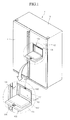
- FIG. 1 is an external perspective view of a refrigerator according to an embodiment of the present invention.
- FIG. 2 is a side cross-sectional view of the refrigerator.
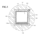
- FIG. 3 is a cross-sectional view taken along line I-I' of FIG. 1 .
- FIG. 4 is a cross-sectional view illustrating a home bar heater according to a second embodiment.
- FIG. 5 is a cross-sectional view illustrating a home bar heater according to a third embodiment.
- FIG. 6 is a block view showing the refrigerator according to an embodiment of the present invention.
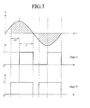
- FIG. 7 is a view showing a case where the input voltage is changed stepwise in a system for controlling a home bar heater according to an embodiment of the present invention.
- FIG. 8 is a flow chart showing a method for controlling the home bar heater according to the opening of the home bar door.
- FIG. 1 is an external perspective view of a refrigerator according to an embodiment of the present invention and FIG. 2 is a side cross-sectional view of the refrigerator.
- a side-by-side-type refrigerator including a freezer compartment and a refrigerator compartment at left and right sides, will be exemplified in FIG. 1 .
- positions of the freezer compartment and the refrigerator compartment are not limited thereto, and a top-mount-type refrigerator in which a freezer compartment and a refrigerator compartment are vertically arranged, or a bottom freezer-type refrigerator in which a refrigerator compartment is disposed on a top side, and the freezer compartment is disposed on a bottom side may be provided according to other embodiments.
- a refrigerator 1 includes a main body 10 having a refrigerating chamber 17 and a freezing chamber (not shown) therein, a freezing chamber door 11 that opens and closes the freezing chamber, a refrigerating chamber door 12 that opens and closes the refrigerating chamber 17, a machine chamber 20 that is formed on a rear surface of the main body 10, and a compressor 19 that is received in the inside of the machine chamber 20.
- the rear surface of the main body 10 is mounted with an evaporator 21 so that cold air is supplied to the refrigerating chamber 17 or the freezing chamber.
- a receiving shelf 18 and a receiving box 22 are provided inside the refrigerating chamber 17.
- a shelf and other receiving boxes having the same function as the foregoing shelf and receiving box are provided inside the freezing chamber.
- the rear surface of the refrigerating chamber door 12 may be mounted with a plurality of door baskets 131.
- a home bar structure 100 is provided at the refrigerating door 12 such that a user can insert or withdraw objects such as drinks in or from the refrigerating chamber without opening the refrigerating chamber door 12.
- the home bar 100 may be provided on the freezer compartment door 11, or on both the refrigerator compartment door 12 and the freezer compartment door 11.
- the home bar 100 includes an opening 101, a home bar frame 102, and a home bar door 103. Those elements are combined with a home bar case 152 that is provided at a rear surface of the refrigerating chamber door 12, and a home bar cover 153 that can selectively open and close the home bar case 152 in a state where the refrigerating chamber door 12 is opened.
- the opening 101 allows access to good inside the refrigerator.
- the home bar frame 102 is disposed on a periphery around the opening 101 to form an appearance of the home bar 100.
- the home bar door 103 is configured to open and close the opening 101.
- the opening 101 and the home bar frame 102 which are separately referred in function, are included in the home bar 100, the opening 101 and the home bar frame 102 may be considered as portions of the refrigerator compartment door 12.
- An inner surface of the home bar door 103 is provided with a home bar door liner 104.
- the home bar door liner 104 contacts the home bar frame 102 to close an inner space of the refrigerator 1 in the state where the home bar door 103 covers the opening 101.
- the home bar door 103 is rotatably mounted at a lower end of the home bar 100, i.e., a hinge portion 107.
- the hinge portion 107 may be provided to the refrigerator compartment door 12 on both sides of a lower end of the opening 101.
- the home bar door 103 includes a latch member 106 in an inner upper portion thereof.
- the latch member 106 fixes the home bar door 103 covering the opening 101 to the home bar frame 102.
- the home bar frame 102 includes a latch assembly 105 that is, when the home bar door 103 is closed, interlocked with the latch member 106.
- the home bar door 103 When the home bar door 103 is closed, the latch member 106 is inserted into the latch assembly 105 and interlocked with the latch assembly 105, to maintain the closing state of the home bar door 103.
- the home bar door 103 includes a push part (not shown) in a front surface thereof.
- the push part is configured to perform a push operation for a user to open the home bar door 103.
- the latch member 106 with the push part may be one element of an "opening/closing device" for opening/closing the home bar door 103.
- the home bar frame 102 includes a gasket 108 in a front surface thereof.
- the gasket 108 in the state where the home bar door 103 is closed, contacts the inner surface of the home bar door 103 to close the inner space of the refrigerator 1, thereby preventing the leakage of cool air in the refrigerator 1.
- the home bar frame 102 includes a home bar heater 120 therein.
- the home bar heater 120 heats the periphery of the opening 101 to prevent wet air, i.e., moisture in air from being condensed by a temperature difference between the inside and the outside of the refrigerator 1.
- FIG. 3 is a cross-sectional view taken along line I-I' of FIG. 1 .
- the home bar heater 120 may be disposed inside the home bar frame 102.
- the home bar frame 102 may include an insulation material inserted into the home bar frame 102 to thermally insulate the inside and the outside of the refrigerator 1 from each other.
- the home bar heater 120 is disposed around the opening 101.
- the home bar heater 120 includes an upper end 121 disposed on an upper side of the opening 101, a first side end 122 extending from the upper end 121 and disposed on at least one of left and right sides of the opening 101, a lower end 123 extending from the first side end 122 and disposed on a lower side of the opening 101, and a second side end 124 extending from the lower end 123 and disposed on at least another side of the left and right sides of the opening 101.
- the second side end 124 may be opposite to the first side end 122 with respect to the opening 101.
- the upper end 121 and the side ends 122 and 124 may include a heater formed of an electrical heating wire disposed in a single line.
- the lower end 123 may include a heater disposed in a plurality of lines, i.e., a multi-stage. That is, in the lower end 123 the electrical heating wire may be disposed in a zigzag shape downward from the lower side of the opening 101.
- the home bar door 103 is hinged to the lower portion of the home bar frame 102.
- a relatively small amount of the insulation material is inserted into the lower portion of the home bar frame 102 to obtain a space allowing rotation of the home bar door 103.
- the lower portion of the home bar frame 102 has a lower temperature than those of the other portions.
- the possibility of condensing moisture in air is increased.
- the home bar heater 120 may be provided in a plurality of lines in the lower portion of the home bar frame 102 to supply a larger amount of heat to the lower portion of the home bar frame 102. That is, more and longer portions of the home bar heater 120 may be disposed on the lower side of the home bar frame 102 than on the other sides.
- the lower end 123 of the home bar heater 120 includes the heater having a plurality of layers.
- the lower end 123 is disposed in a horizontal direction in a zigzag shape, and includes a plurality of bent portions 123a in at least one portion of the lower end 123 such that the heater is disposed in the plurality of lines.
- the respective lines of the heater may be spaced from each other by a predetermined distance.
- the heater of the lower end 123 is disposed in a plurality of lines, the heater produces a large quantity of heat, and thus greatly heats the refrigerator door. As a result, a relatively low temperature of the lower portion of the home bar frame 102 increases to temperatures of the other portions, i.e., upper and side portions of the home bar frame 102.
- the number of the lines of the heater arranged in the lower end 123 may be determined based on differences between a lower temperature of the home bar frame 102 and temperatures of the other portions of the home bar frame 102.
- One side of the lower end 123 is connected to one side of the first side end 122, and the other side of the lower end 123 is connected to one side of the second side end 124. That is, the side ends 122 and 124 may be integrally formed with the lower end 123.
- the side ends 122 and 124, and the upper end 121 are disposed in a single line as illustrated in FIG. 3 , the number of the lines is not limited thereto, provided that the number is less than that of the lower end 123.
- the number of arranged heater lines in the side ends 122 and 124, and the upper end 121 may be less than that of the lower end 123.
- the home bar heater 120 may be connected to a controller (not shown) configured to control operation of the home bar heater 120. Particularly, one side of the upper end 121 and one side of the second side end 124 may be connected to the controller.
- the power may be supplied to the home bar heater 120.
- the refrigerator 1 may include a temperature sensor therein, which is configured to measure an inner temperature of the refrigerator 1.
- the refrigerator 1 may also have a configuration where a temperature measured by the temperature sensor is compared with an outer temperature of the refrigerator 1, and when the measured temperature is greater than a predetermined value, the home bar heater 120 is operated.
- FIG. 4 is a cross-sectional view illustrating the home bar heater 220 according to one embodiment.
- the home bar heater 220 may be disposed inside the home bar frame 102.
- the home bar heater 220 is disposed around the opening 101.
- the home bar heater 220 includes an upper end 221 disposed on an upper side of the opening 101, a first side end 222 extending from the upper end 221 and disposed on at least one of left and right sides of the opening 101, a lower end 223 extending from the first side end 222 and disposed on a lower side of the opening 101, and a second side end 224 extending from the lower end 223 and disposed on at least another side of the left and right sides of the opening 101.
- the second side end 224 may be opposite to the first side end 222 with respect to the opening 101.
- the upper end 221 and the side ends 222 and 224 may include a heater disposed in a single line.
- the lower end 223 may include a heater disposed in a plurality of lines.
- the heater supplies a larger amount of heat to the lower portion of the home bar frame 102 than to the other portions.
- the home bar heater 220 includes a left side 223a and a right side 223b in the lower end 223, which are laterally symmetrical to each other with respect to a center of the lower end 223. Respective lines of the heater disposed on the left side 223a and the right side 223b may be spaced from each other by a predetermined distance.
- the heater of the lower end 223 is disposed in a plurality of lines, the heater produces a large amount of heat, and thus greatly heats the refrigerator door. As a result, a relatively low temperature in the lower portion of the home bar frame 102 increases to temperatures of the other portions.
- the number of the lines of the heater arranged in the lower end 223 may be determined based on differences between the temperature of the lower portion of the home bar frame 102 and the temperatures of the other portions of the home bar frame 102.
- the home bar heater 220 may be connected to a controller (not shown) configured to control operation of the home bar heater 220. Particularly, one side of the upper end 221 and one side of the second side end 224 may be connected to the controller.
- FIG. 5 is a cross-sectional view illustrating the home bar heater 320 according to another embodiment.
- the home bar heater 320 may be disposed inside the home bar frame 102.
- the home bar heater 320 is disposed around the opening 101.
- the home bar heater 320 includes a first side end 321 disposed on a right side of the opening 101, an upper end 322 extending from the first side end 321 and disposed on an upper side of the opening 101, a second side end 323 extending from the upper end 322 and disposed on a left side of the opening 101, and a lower end 324 extending from the second side end 323 and disposed on the lower side of the opening 101.
- One side of the first side end 321 is connected to a controller controlling the home bar heater 320.
- One side of the lower end 324 is also connected to the controller. That is, the home bar heater 320 may be connected to the controller through the side of the first side end 321, and extended from the first side end 321 to the lower end 324, and then connected again to the controller through the side of the lower end 324.
- the side of the first side end 321 and the side of the lower end 324 may connected to the controller through wires (not shown).
- the lower end 324 includes a heater disposed in a plurality of lines.
- the upper end 322 and the side ends 321 and 323 may include a heater disposed in a single line.
- the lower end 324 may include the heater disposed in the plurality of lines.
- the heater supplies the larger amount of heat to the lower portion of the home bar frame 102 than to the other portions.
- the upper end 322 and the side ends 321 and 323 may also have a heater having a plurality of lines, provided that the heater of the lower end 324 has more lines than that of the upper end 322 and the side ends 321 and 323.
- the heater of the lower end 324 is disposed in the plurality of lines, the heater produces the large amount of heat, and thus greatly heats the refrigerator door. As a result, a relatively low temperature in the lower portion of the home bar frame 102 increases to temperatures of the other portions.
- the above table 1 shows a required length of the heater and a consumed amount of heat per unit length in the arrangement of the heaters in both a related art and the above embodiments.
- the freezer compartment home bar includes a heater of about 1,110 mm, and the amount of heat per unit length is about 0.0050 W/mm, and thus the total amount of heat consumed is about 5.5 W
- the refrigerator compartment home bar includes a heater of about 1,280 mm, and the amount of heat per unit length is about 0.0059 W/mm, and thus the total amount of heat consumed is about 7.6 W.
- the freezer compartment home bar includes a heater of about 1,700 mm, and the amount of heat per unit length is about 0.0027 W/mm, and thus the total amount of heat consumed is about 4.6 W.
- the refrigerator compartment home bar includes a heater of about 2,020 mm, and the amount of heat per unit length is about 0.0021 W/mm, and thus the total amount of heat consumed is about 4.2 W.
- the freezer compartment home bar includes a heater of about 1,465 mm, and the amount of heat per unit length is about 0.0031 W/mm, and thus the total amount of heat consumed is about 4.6 W.
- the refrigerator compartment home bar includes a heater of about 1,855 mm, and the amount of heat per unit length is about 0.0023 W/mm, and thus the total amount of heat consumed is about 4.2 W.
- the freezer compartment home bar includes a heater of about 1,390 mm, and the amount of heat per unit length is about 0.0033 W/mm, and thus the total amount of heat consumed is about 4.6 W.
- the refrigerator compartment home bar includes a heater of about 1,680 mm, and the amount of heat per unit length is about 0.0025 W/mm, and thus the total amount of heat consumed is about 4.2 W.
- the total amount of heat consumed i.e., a power consumption of the heaters arranged according to the above embodiments is less than that of the related art home bar heaters.
- the heater of the present disclosure needs less amount of heat per length unit to supply a greater amount of heat to the lower end since the lower end requiring the greater amount of heat includes the plurality of lines.
- the home bar heater 120 is operated according to a chamber temperature of a space in which the refrigerator 1 is installed or according to the opening and closing of the home bar door 103.
- the voltage (or current) applied to the home bar heater 120 can be variably controlled by the controller.
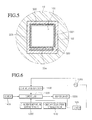
- FIG. 6 is a schematic block view showing the refrigerator according to an embodiment of the present invention.
- the refrigerator includes a power supply unit 1200 that receives power from an AC source (not shown), a zero voltage detector 1100 that detects zero voltage of power supplied from the power supply unit 1200, a controller 1000 that receives a detect signal from the zero voltage detector 1100, a room temperature sensor 1300 that detects the temperature of a space in which the refrigerator 1 is installed; a home bar door opening sensor 1600 that detects the opening and closing of the home bar door 15, a heater driver 1500 that controls the home bar heater 120, and a memory 1400 that is connected to the controller 1000 and stores data such as a voltage value to be applied according to the a room temperature.
- the controller 1000 receives the zero voltage detecting signals transmitted from the zero voltage detector 1100 and controls the voltage to be input to the heater driver 1500 after a predetermined time elapses from a point in time of the zero voltage.
- the controller 1000 receives from the memory 1400 the required input voltage corresponding to the temperature value that is transmitted from the room temperature sensor 1300. Thereafter, the controller 1000 controls the voltage to be input to the heater driver 1500.
- the controller 1000 receives the detecting signal transmitted from the home bar door opening sensor 1600 to transmit the input voltage value according to the opening or closing and the opening time of the home bar door 15 to the heater driver 1500.
- the heater driver 1500 controls a turn-on time of the home bar heater 120 to determine the input voltage.
- the heater driver 1500 uses a simple relay unit. Such units usually perform an on/off operation, but the described embodiment of the present invention uses a semiconductor switch device that performs a function of providing variably the voltage to the home bar heater 120 together with an on/off switch function .
- the heater driver 1500 corresponding to the semiconductor switch device as described above includes a triac or a thyristor, etc.
- the amount of voltage applied can be changed according to the room temperature. The point in time when the voltage is applied varies through the zero voltage detector 1100, making it possible to change the voltage value input to the home bar heater 120.
- FIG. 7 is a view showing a case where the input voltage is changed stepwise in a system for controlling a home bar heater according to an embodiment of the present invention.
- a commercial alternative voltage of 220V is applied through the power supply unit 1200.
- the duty time of the heater driver is properly controlled according to the room temperature, making it possible to change the applied voltage.
- the duty time of the heater driver is properly controlled according to the opening or closing and opening time of the home bar door 15, making it possible to change the applied voltage.
- the turn-on time or duration (duty II) of the heater driver is long. If the voltage application point in time is delayed, the turn-on time (duty I) of the heater driver is short. In other words, the input power is increased and decreased by ⁇ V according to the increase or decrease of the turn-on time.
- the driving of the home bar heater can be controlled according to the room temperature or the opening or closing of the home bar door 15 through the control of the turn-on time of the heater driver 1500, making it possible to prevent the edge part of the home bar door 15 from being damped.
- FIG. 8 is a flow chart showing a method for controlling the home bar heater according to the opening of the home bar door.
- a basic input voltage is applied to the home bar heater, such that the home bar heater 120 is turned-on (S11).
- the basic input voltage is a voltage that is reduced while the commercial voltage of 220V passes through a transformer (or inverter).
- the controller 1000 detects the opening or closing of the home bar door 15 (S12).
- the opening or closing of the home bar door 15 is detected by receiving the detecting signal transmitted from the home bar door opening sensor 1600.
- the time is counted from an instant when the home bar door 15 is opened (S13). Latter, a closing of the home bar door 15 is also detected (S14). If it is judged that the home bar door 15 is closed, the time count stops (S15).
- an increased amount of voltage ( ⁇ V) is determined according to the opening or closing and opening time of the home bar door 15 and is added to the basic input voltage (V) (S16).
- the increased amount of voltage ( ⁇ V) can be tabled in the memory 1400, and the controller 1000 can read in the data stored in the memory 1400 to compare and judge each numerical value.
- the increased amount in voltage having a predetermined amount may be added whenever the home bar door 1 is opened or closed.
- the increased amount in voltage can be set according to the time when the home bar door 15 is opened. Also, the increased amount in voltage may be added according to the opened time by counting how long the home bar door 15 was open.
- the turn-on time of the heater driver 1500 can properly be controlled as shown in FIG. 7
- the controller 1000 judges whether the increased input voltage has reached the upper limit voltage (S18).
- the maximum voltage which can be input to the home bar heater 120 is a commercial voltage of 220V and the minimum value is OV. Therefore, when the value corresponding to the increased amount in voltage added to the previous input voltage value, is above the commercial voltage of 220V, the input voltage is maintained to the upper value (S19).
- the input voltage value is returned to the basic input voltage (S23). When the setting time does not elapse, it is judged whether the home bar door 15 is re-opened in the controller 1000 (S21).
- the voltage supplied to the home bar heater 120 according to the room temperature of the refrigerator is controlled variably and even when the room temperature is constant, the input voltage is changed according to the opening or closing of the home bar door 15, making it possible to minimized power consumption according to the driving of the home bar heater 120.
- the phenomenon wherein the edge part of the home bar door 15 becomes damp can be effectively be prevented while minimizing power consumption.
Landscapes
- Engineering & Computer Science (AREA)
- Chemical & Material Sciences (AREA)
- Combustion & Propulsion (AREA)
- Physics & Mathematics (AREA)
- Mechanical Engineering (AREA)
- Thermal Sciences (AREA)
- General Engineering & Computer Science (AREA)
- Devices That Are Associated With Refrigeration Equipment (AREA)
- Refrigerator Housings (AREA)
Applications Claiming Priority (2)
| Application Number | Priority Date | Filing Date | Title |
|---|---|---|---|
| KR20080017597 | 2008-02-27 | ||
| KR1020090012750A KR20090092702A (ko) | 2008-02-27 | 2009-02-17 | 냉장고 및 냉장고의 제어 방법 |
Publications (3)
| Publication Number | Publication Date |
|---|---|
| EP2096391A2 true EP2096391A2 (fr) | 2009-09-02 |
| EP2096391A3 EP2096391A3 (fr) | 2016-11-30 |
| EP2096391B1 EP2096391B1 (fr) | 2018-02-14 |
Family
ID=40673160
Family Applications (1)
| Application Number | Title | Priority Date | Filing Date |
|---|---|---|---|
| EP09153573.2A Ceased EP2096391B1 (fr) | 2008-02-27 | 2009-02-25 | Réfrigérateur et procédé pour son contrôle |
Country Status (1)
| Country | Link |
|---|---|
| EP (1) | EP2096391B1 (fr) |
Cited By (2)
| Publication number | Priority date | Publication date | Assignee | Title |
|---|---|---|---|---|
| ITVA20120040A1 (it) * | 2012-10-18 | 2014-04-19 | Whirlpool Co | Frigorifero con sportello sulla porta per l¿accesso ad una porzione interna del comparto refrigerato |
| CN116558205A (zh) * | 2023-05-30 | 2023-08-08 | 长虹美菱股份有限公司 | 一种风门防冻装置 |
Family Cites Families (4)
| Publication number | Priority date | Publication date | Assignee | Title |
|---|---|---|---|---|
| KR100853681B1 (ko) * | 2002-05-24 | 2008-08-25 | 엘지전자 주식회사 | 냉장고의 홈바히터 제어방법 |
| US6862891B2 (en) * | 2003-06-02 | 2005-03-08 | General Electric Company | Methods and apparatus for controlling heating within refrigerators |
| KR20070040120A (ko) * | 2005-10-11 | 2007-04-16 | 주식회사 대우일렉트로닉스 | 냉장고 홈바의 냉기 단속장치 |
| KR101457686B1 (ko) * | 2008-01-31 | 2014-11-03 | 엘지전자 주식회사 | 냉장고 |
-
2009
- 2009-02-25 EP EP09153573.2A patent/EP2096391B1/fr not_active Ceased
Cited By (2)
| Publication number | Priority date | Publication date | Assignee | Title |
|---|---|---|---|---|
| ITVA20120040A1 (it) * | 2012-10-18 | 2014-04-19 | Whirlpool Co | Frigorifero con sportello sulla porta per l¿accesso ad una porzione interna del comparto refrigerato |
| CN116558205A (zh) * | 2023-05-30 | 2023-08-08 | 长虹美菱股份有限公司 | 一种风门防冻装置 |
Also Published As
| Publication number | Publication date |
|---|---|
| EP2096391B1 (fr) | 2018-02-14 |
| EP2096391A3 (fr) | 2016-11-30 |
Similar Documents
| Publication | Publication Date | Title |
|---|---|---|
| US8028538B2 (en) | Refrigerator with temperature control and operating method therefor | |
| US10190813B2 (en) | Refrigerator and method for controlling the same | |
| CN100552337C (zh) | 带有温度控制的冰箱及其操作方法 | |
| AU2018202121B2 (en) | Refrigerator and method for controlling the same | |
| EP2420773A2 (fr) | Réfrigérateur | |
| EP3132214B1 (fr) | Réfrigérateur | |
| EP3396280B1 (fr) | Procédé de commande d'un réfrigérateur | |
| WO2009113310A1 (fr) | Réfrigérateur | |
| KR101457686B1 (ko) | 냉장고 | |
| AU2015410544A1 (en) | Refrigerator | |
| KR20160001389A (ko) | 냉장고 및 그 제어 방법 | |
| EP2096391B1 (fr) | Réfrigérateur et procédé pour son contrôle | |
| KR20120072779A (ko) | 제상히터를 구비한 냉장고 | |
| KR20110139977A (ko) | 냉장고 | |
| KR20090092702A (ko) | 냉장고 및 냉장고의 제어 방법 | |
| KR101505675B1 (ko) | 냉장고 | |
| US20160084565A1 (en) | Refrigerator appliance and method of operating a refrigerator appliance | |
| EP2175216A1 (fr) | Réfrigérateur à porte unique et procédé de commande d'un tel réfrigérateur | |
| KR20050006844A (ko) | 냉온장고를 구비한 테이블 | |
| KR100575670B1 (ko) | 냉장고의 홈바히터 제어방법 | |
| KR101426566B1 (ko) | 냉장고의 홈바 히터 제어 시스템 및 제어 방법 | |
| KR100485938B1 (ko) | 냉장고의 정온 제어 방법 | |
| WO2016070893A1 (fr) | Appareil de réfrigération à performance de réfrigération et consommation d'énergie améliorées | |
| KR100700761B1 (ko) | 냉장고의 해동장치 | |
| JP2006226587A (ja) | ショーケース |
Legal Events
| Date | Code | Title | Description |
|---|---|---|---|
| PUAI | Public reference made under article 153(3) epc to a published international application that has entered the european phase |
Free format text: ORIGINAL CODE: 0009012 |
|
| 17P | Request for examination filed |
Effective date: 20090225 |
|
| AK | Designated contracting states |
Kind code of ref document: A2 Designated state(s): AT BE BG CH CY CZ DE DK EE ES FI FR GB GR HR HU IE IS IT LI LT LU LV MC MK MT NL NO PL PT RO SE SI SK TR |
|
| AX | Request for extension of the european patent |
Extension state: AL BA RS |
|
| PUAL | Search report despatched |
Free format text: ORIGINAL CODE: 0009013 |
|
| AK | Designated contracting states |
Kind code of ref document: A3 Designated state(s): AT BE BG CH CY CZ DE DK EE ES FI FR GB GR HR HU IE IS IT LI LT LU LV MC MK MT NL NO PL PT RO SE SI SK TR |
|
| AX | Request for extension of the european patent |
Extension state: AL BA RS |
|
| RIC1 | Information provided on ipc code assigned before grant |
Ipc: F25D 23/04 20060101ALI20161021BHEP Ipc: F25D 23/02 20060101AFI20161021BHEP |
|
| AKX | Designation fees paid |
Designated state(s): DE FR GB IT |
|
| AXX | Extension fees paid |
Extension state: RS Extension state: AL Extension state: BA |
|
| GRAP | Despatch of communication of intention to grant a patent |
Free format text: ORIGINAL CODE: EPIDOSNIGR1 |
|
| STAA | Information on the status of an ep patent application or granted ep patent |
Free format text: STATUS: GRANT OF PATENT IS INTENDED |
|
| RIC1 | Information provided on ipc code assigned before grant |
Ipc: F25D 23/02 20060101AFI20170731BHEP Ipc: F25D 23/04 20060101ALI20170731BHEP |
|
| INTG | Intention to grant announced |
Effective date: 20170830 |
|
| GRAS | Grant fee paid |
Free format text: ORIGINAL CODE: EPIDOSNIGR3 |
|
| GRAA | (expected) grant |
Free format text: ORIGINAL CODE: 0009210 |
|
| STAA | Information on the status of an ep patent application or granted ep patent |
Free format text: STATUS: THE PATENT HAS BEEN GRANTED |
|
| AK | Designated contracting states |
Kind code of ref document: B1 Designated state(s): DE FR GB IT |
|
| REG | Reference to a national code |
Ref country code: GB Ref legal event code: FG4D |
|
| REG | Reference to a national code |
Ref country code: DE Ref legal event code: R096 Ref document number: 602009050717 Country of ref document: DE |
|
| PG25 | Lapsed in a contracting state [announced via postgrant information from national office to epo] |
Ref country code: IT Free format text: LAPSE BECAUSE OF FAILURE TO SUBMIT A TRANSLATION OF THE DESCRIPTION OR TO PAY THE FEE WITHIN THE PRESCRIBED TIME-LIMIT Effective date: 20180214 |
|
| REG | Reference to a national code |
Ref country code: DE Ref legal event code: R097 Ref document number: 602009050717 Country of ref document: DE |
|
| PLBE | No opposition filed within time limit |
Free format text: ORIGINAL CODE: 0009261 |
|
| STAA | Information on the status of an ep patent application or granted ep patent |
Free format text: STATUS: NO OPPOSITION FILED WITHIN TIME LIMIT |
|
| 26N | No opposition filed |
Effective date: 20181115 |
|
| GBPC | Gb: european patent ceased through non-payment of renewal fee |
Effective date: 20180514 |
|
| PG25 | Lapsed in a contracting state [announced via postgrant information from national office to epo] |
Ref country code: GB Free format text: LAPSE BECAUSE OF NON-PAYMENT OF DUE FEES Effective date: 20180514 Ref country code: FR Free format text: LAPSE BECAUSE OF NON-PAYMENT OF DUE FEES Effective date: 20180414 |
|
| PGFP | Annual fee paid to national office [announced via postgrant information from national office to epo] |
Ref country code: DE Payment date: 20220105 Year of fee payment: 14 |
|
| REG | Reference to a national code |
Ref country code: DE Ref legal event code: R119 Ref document number: 602009050717 Country of ref document: DE |
|
| PG25 | Lapsed in a contracting state [announced via postgrant information from national office to epo] |
Ref country code: DE Free format text: LAPSE BECAUSE OF NON-PAYMENT OF DUE FEES Effective date: 20230901 |