EP2096462B1 - Appareil de détection d'objet - Google Patents
Appareil de détection d'objet Download PDFInfo
- Publication number
- EP2096462B1 EP2096462B1 EP08722269A EP08722269A EP2096462B1 EP 2096462 B1 EP2096462 B1 EP 2096462B1 EP 08722269 A EP08722269 A EP 08722269A EP 08722269 A EP08722269 A EP 08722269A EP 2096462 B1 EP2096462 B1 EP 2096462B1
- Authority
- EP
- European Patent Office
- Prior art keywords
- object detecting
- range
- distance
- scan
- scan range
- Prior art date
- Legal status (The legal status is an assumption and is not a legal conclusion. Google has not performed a legal analysis and makes no representation as to the accuracy of the status listed.)
- Not-in-force
Links
- 238000003384 imaging method Methods 0.000 claims abstract description 10
- 238000001514 detection method Methods 0.000 claims description 28
- 238000000034 method Methods 0.000 description 6
- 238000010586 diagram Methods 0.000 description 4
- 230000005540 biological transmission Effects 0.000 description 1
- 230000000694 effects Effects 0.000 description 1
- 230000003287 optical effect Effects 0.000 description 1
Images

Classifications
-
- G—PHYSICS
- G01—MEASURING; TESTING
- G01S—RADIO DIRECTION-FINDING; RADIO NAVIGATION; DETERMINING DISTANCE OR VELOCITY BY USE OF RADIO WAVES; LOCATING OR PRESENCE-DETECTING BY USE OF THE REFLECTION OR RERADIATION OF RADIO WAVES; ANALOGOUS ARRANGEMENTS USING OTHER WAVES
- G01S13/00—Systems using the reflection or reradiation of radio waves, e.g. radar systems; Analogous systems using reflection or reradiation of waves whose nature or wavelength is irrelevant or unspecified
- G01S13/88—Radar or analogous systems specially adapted for specific applications
- G01S13/93—Radar or analogous systems specially adapted for specific applications for anti-collision purposes
- G01S13/931—Radar or analogous systems specially adapted for specific applications for anti-collision purposes of land vehicles
-
- G—PHYSICS
- G01—MEASURING; TESTING
- G01S—RADIO DIRECTION-FINDING; RADIO NAVIGATION; DETERMINING DISTANCE OR VELOCITY BY USE OF RADIO WAVES; LOCATING OR PRESENCE-DETECTING BY USE OF THE REFLECTION OR RERADIATION OF RADIO WAVES; ANALOGOUS ARRANGEMENTS USING OTHER WAVES
- G01S13/00—Systems using the reflection or reradiation of radio waves, e.g. radar systems; Analogous systems using reflection or reradiation of waves whose nature or wavelength is irrelevant or unspecified
- G01S13/86—Combinations of radar systems with non-radar systems, e.g. sonar, direction finder
- G01S13/867—Combination of radar systems with cameras
-
- G—PHYSICS
- G01—MEASURING; TESTING
- G01S—RADIO DIRECTION-FINDING; RADIO NAVIGATION; DETERMINING DISTANCE OR VELOCITY BY USE OF RADIO WAVES; LOCATING OR PRESENCE-DETECTING BY USE OF THE REFLECTION OR RERADIATION OF RADIO WAVES; ANALOGOUS ARRANGEMENTS USING OTHER WAVES
- G01S17/00—Systems using the reflection or reradiation of electromagnetic waves other than radio waves, e.g. lidar systems
- G01S17/02—Systems using the reflection of electromagnetic waves other than radio waves
- G01S17/06—Systems determining position data of a target
- G01S17/42—Simultaneous measurement of distance and other co-ordinates
-
- G—PHYSICS
- G01—MEASURING; TESTING
- G01S—RADIO DIRECTION-FINDING; RADIO NAVIGATION; DETERMINING DISTANCE OR VELOCITY BY USE OF RADIO WAVES; LOCATING OR PRESENCE-DETECTING BY USE OF THE REFLECTION OR RERADIATION OF RADIO WAVES; ANALOGOUS ARRANGEMENTS USING OTHER WAVES
- G01S17/00—Systems using the reflection or reradiation of electromagnetic waves other than radio waves, e.g. lidar systems
- G01S17/88—Lidar systems specially adapted for specific applications
- G01S17/93—Lidar systems specially adapted for specific applications for anti-collision purposes
- G01S17/931—Lidar systems specially adapted for specific applications for anti-collision purposes of land vehicles
-
- G—PHYSICS
- G01—MEASURING; TESTING
- G01S—RADIO DIRECTION-FINDING; RADIO NAVIGATION; DETERMINING DISTANCE OR VELOCITY BY USE OF RADIO WAVES; LOCATING OR PRESENCE-DETECTING BY USE OF THE REFLECTION OR RERADIATION OF RADIO WAVES; ANALOGOUS ARRANGEMENTS USING OTHER WAVES
- G01S17/00—Systems using the reflection or reradiation of electromagnetic waves other than radio waves, e.g. lidar systems
- G01S17/86—Combinations of lidar systems with systems other than lidar, radar or sonar, e.g. with direction finders
-
- G—PHYSICS
- G01—MEASURING; TESTING
- G01S—RADIO DIRECTION-FINDING; RADIO NAVIGATION; DETERMINING DISTANCE OR VELOCITY BY USE OF RADIO WAVES; LOCATING OR PRESENCE-DETECTING BY USE OF THE REFLECTION OR RERADIATION OF RADIO WAVES; ANALOGOUS ARRANGEMENTS USING OTHER WAVES
- G01S13/00—Systems using the reflection or reradiation of radio waves, e.g. radar systems; Analogous systems using reflection or reradiation of waves whose nature or wavelength is irrelevant or unspecified
- G01S13/88—Radar or analogous systems specially adapted for specific applications
- G01S13/93—Radar or analogous systems specially adapted for specific applications for anti-collision purposes
- G01S13/931—Radar or analogous systems specially adapted for specific applications for anti-collision purposes of land vehicles
- G01S2013/9327—Sensor installation details
- G01S2013/93271—Sensor installation details in the front of the vehicles
Definitions
- the present invention relates to an object detecting apparatus.
- JP 2006-221498 A discloses an object detecting apparatus mounted on a vehicle in accordance with the preamble of claim 1. The data acquired from both a radar and a video camera are processed to detect whether or not it is possible for the vehicle to pass through detected objects.
- JP 2001-155291 A discloses an object detecting apparatus with a road side stationary camera which is rotatable for detecting vehicles passing the stationary camera. The document discloses a setting device formed by an input part, for example, a keyboard or a mouse.
- a laser radar sensor is mounted to a vehicle and is actuated by an actuator to change a direction of the optical axis of this laser radar sensor, based on image taken by the camera.
- the present invention has an object of providing an object detecting apparatus that can detect an object in an arbitrary range, and obtain the distance between a plurality of objects.
- an object detecting apparatus includes: an object detecting device that causes electromagnetic waves to be reflected from an object and receives the reflected waves to detect the object while scanning a predetermined scan range; a rotating device that changes a direction of the object detecting device; an imaging device that captures images; a display device that displays an image captured by the imaging device; a setting device that sets the scan range of the object detecting device on the image displayed by the display device; and a control device that instructs the rotating device to rotate the object detecting device based on the set scan range, and instructs the object detecting device to scan the scan range.
- the object detecting apparatus since it has a rotating device that changes the direction of the object detecting device, then even in the case where an object detecting device with a narrow scan range is used, it is possible to detect objects in an arbitrary range. Furthermore, since it has a setting device that sets the scan range of the object detecting device on the image displayed, it is possible to set the scan range easily according to the intention of an operator. Moreover, since it has a control device that instructs the rotating device to rotate the object detecting device, and instructs the object detecting device to scan the scan range, then even if the scanning location of the object detecting device cannot be seen visually, it is possible to rotate the object detecting device with respect to the set scan range automatically, and scan.
- the object detecting apparatus further includes: a reflection point detecting device that detects a plurality of reflection points of the reflected waves from locations at a predetermined distance from the imaging device, based on a detection result of the object detecting device; and a reflection point-to-point distance computing device that calculates a distance between the plurality of reflection points.
- a reflection point detecting device that detects a plurality of reflection points of the reflected waves from locations at a predetermined distance from the imaging device, based on a detection result of the object detecting device
- a reflection point-to-point distance computing device that calculates a distance between the plurality of reflection points. In this case, it is possible to calculate the distance between the plurality of reflection points to obtain the distance between the plurality of objects.
- control device determines whether or not the distance calculated by the reflection point-to-point distance computing device is greater than a predetermined value, and instruct the display device to display the result. In this case, the operator can determine at a glance whether or not the calculated distance is greater than the predetermined value.
- control device instructs the rotating device to rotate the object detecting device so that a center of the scan of the object detecting device matches a center of the scan range set by the setting device. In this case, even in the case where an object detecting device with a narrow scan range is employed, it is possible to detect objects in a desired range reliably.
- the object detecting apparatus of the present invention it is possible to detect objects in an arbitrary range, and obtain the distance between a plurality of objects. Furthermore, when detecting the objects, it is possible to set a scan range easily, and automatically scan the set scan range.
- FIG. 1 is a schematic block diagram of an object detecting apparatus according to the present embodiment.
- An object detecting apparatus 1 is mounted on a vehicle 5, and is provided with: a radar (object detecting device) 10 that receives reflected waves from an object to detect the object by scanning a predetermined scan range using electromagnetic waves; a camera (imaging device) 20 that captures images; a display (display device) 30 that displays an image captured by the camera 20; a touch panel (setting device) 30a that sets the scan range of the radar 10 on the image displayed on the display 30; and a control device 40 that instructs the radar 10 to scan the set scan range.
- a radar object detecting device 10 that receives reflected waves from an object to detect the object by scanning a predetermined scan range using electromagnetic waves
- a camera imaging device
- a display display
- touch panel (setting device) 30a that sets the scan range of the radar 10 on the image displayed on the display 30
- a control device 40 that instructs the radar 10 to scan the set scan range.
- the radar 10 such as a laser radar, a millimeter wave radar, or the like, is mounted on the front of the vehicle 5.
- the radar 10 is provided with a transmitting section that transmits electromagnetic waves and a receiving section that receives reflected waves.
- the transmitting section can scan a predetermined angular range (- ⁇ 2 to + ⁇ 1) while transmitting electromagnetic waves forward.
- the receiving section receives reflected waves that are transmitted from the transmitting section and reflected from objects.
- the radar 10 is mounted on a motor 10a.
- the motor 10a is constituted by a stepper motor or the like, and the rotation shaft is arranged in the vertical direction.
- the motor 10a mounted on the rotation shaft can rotate in the horizontal plane.
- the radar 10 rotates only by a rotation angle ⁇ from the vehicle front direction (Rz0 direction), to face in the Rz1 direction.
- the radar 10 can scan the range of the scanning angle between - ⁇ 2 and + ⁇ 1, centered on the Rz1 direction, using electromagnetic waves.
- the camera 20 such as a CCD camera or the like, is mounted on the front of the vehicle 5.
- the camera 20 captures images ahead of the vehicle.
- the display 30 that displays the images captured by the camera 20 is mounted in the compartment of the vehicle 5.
- a transparent touch panel 30a that can recognize a pressed location, is placed on the surface of the display 30.
- a control device 40 is incorporated in an on-board computer or the like.
- the control device 40 calculates the rotation angle ⁇ and the scanning angle - ⁇ 2 to + ⁇ 1 of the radar 10, based on the set scan range of the radar 10. To be specific, it calculates the rotation angle ⁇ of the radar 10 from the coordinates of the central point of the scan range, and calculates the scanning angle - ⁇ 2 to + ⁇ 1 of the radar 10 from the coordinates of the two end points of the scan range. Then it rotates the radar 10 by the calculated rotation angle ⁇ , and also scans the range of the scanning angle - ⁇ 2 to + ⁇ 1 using electromagnetic waves.
- control device 40 is provided with a reflection point detecting device 44 that detects reflection points of the reflected waves from locations at a predetermined distance from the camera 20.
- the reflection point detecting device 44 detects a plurality of reflection points existing at a predetermined distance from the camera 20.
- control device 40 is provided with a reflection point-to-point distance computing device 46 that calculates the distance between a plurality of reflection points. The distance between the plurality of reflection points corresponds to the gap between the plurality of objects existing ahead of the vehicle.
- control device 40 compares the distance between the calculated reflection points and the vehicle width of the vehicle itself registered in advance, and determines whether or not the vehicle itself can pass between the objects. Then, the control device 40 displays the calculated distance between the objects and the determination result of whether or not it can pass through, on the display 30. Moreover, the control device 40 displays the predetermined distance on the display 30 as the distance to the objects.
- an image ahead of a vehicle is captured by the camera 20, and the captured image is displayed on the display 30.
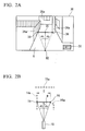
- FIG. 2A is an example of an image displayed on the display device.
- a set button 31 for a vehicle pass detection range is situated at a corner of the image on the display 30.
- An occupant of the vehicle presses the set button 31 to set a detection range (that is, the scan range of the radar 10) for determining whether or not the vehicle can pass through.
- the detection range is set by specifying the detection range on the image using the finger of the occupant.
- the transparent touch panel 30a is placed on the surface of the display 30, the detection range is set by pressing the touch panel 30a.
- the concerned range may be specified by pressing only the start point 34 and the end point 36 of the detection range. Furthermore, the concerned range may be specified by pressing from the start point 34 to the end point 36 in a straight line.
- the road surface 8 between the two is set as the detecting range for determining whether or not the vehicle can pass through.
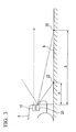
- FIG. 3 is an explanatory diagram of a method of calculating the distance to the central point of the detection range, being a side view ahead of the vehicle.
- the screen coordinates of a specific point on the road surface image, and the distance to the point 22 on the road surface corresponding to the screen coordinates correspond one to one. Accordingly, if the screen coordinates of the central point 35 are known, it is possible to obtain a distance B to a point 25 on the road surface corresponding to the central point 35.
- the control device 40 determines the scanning angle - ⁇ 2 to + ⁇ 1 of the radar 10 from the screen coordinates of the start point 34 and the end point 36 of the detection range as shown in FIG. 2A .
- the angle ⁇ 1 made by the direction corresponding to the central point 35 and the direction corresponding to the start point 34 of the detection range is obtained from the screen coordinates of the central point 35 and the screen coordinates of the start point 34.
- the angle ⁇ 2 made by the direction corresponding to the central point 35 and the direction corresponding to the end point 36 of the detection range is obtained from the screen coordinates of the central point 35 and the screen coordinates of the end point 36.
- the control device 40 drives the motor 10a to rotate the radar 10 based on the calculated rotation angle ⁇ .
- the control device 40 drives the radar 10.
- the radar 10 transmits electromagnetic waves parallel to the road surface, and receives reflected waves from objects. Based on the time from transmission to reception, the distances to the objects are detected. Furthermore, the control device 40 instructs the radar to scan based on the calculated scanning angle - ⁇ 2 to + ⁇ 1.
- FIG. 2B is a plan view of the object detection results from the radar.
- the locations of objects detected outside of the range of the scanning angle - ⁇ 2 to + ⁇ 1 are indicated by broken lines.
- a wall 14a on the left side, a wall 15a at the center rear, and a utility pole 16a on the right side are detected at fixed locations.
- the reflection point detecting device 44 shown in FIG 1 detects a plurality of reflection points of the reflected waves from locations at a predetermined distance B from the camera 20, based on the detection results of the radar 10.
- the predetermined distance B is the distance from the radar 10 to the detection range, and it is possible to employ the distance to the central point of the detection range as a representative.
- the reflection point 14 on the wall 14a and the reflection point 16 on the utility pole 16a are detected as reflection points separated from the radar 10 to the front of the vehicle by the distance B.
- the reflection point-to-point distance computing device 46 as shown in FIG. 1 calculates the distance between the plurality of reflection points.
- the distance C between the reflection point 14 on the wall 14a and the reflection point 16 on the utility pole 16a is calculated.
- the distance C between the two corresponds to the distance between the wall 14a and the utility pole 16a.
- the control device 40 as shown in FIG. 1 compares the distance C between the reflection points calculated by the reflection point-to-point distance computing device 46 with the vehicle width of the vehicle itself registered in advance, and determines whether or not the vehicle itself can pass between the objects. If the distance C between the reflection points is greater than the vehicle width, it determines that it is possible to pass through, and if it is smaller that the vehicle width, it determines that it is not possible to pass through.
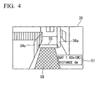
- FIG. 4 is an example of a screen on which the determination results and the like are displayed.
- a display section 51 that displays the determination results and the like from the control device 40 is provided at the corner of the screen of FIG. 4 .
- the display section 51 displays the distance between the objects, the determination result of whether or not it is possible to pass through, and the distance to the objects.
- the distance between the wall 34a and the utility pole 36a is displayed as "Gap 1.92m”
- the determination result of whether or not the vehicle itself can pass through is displayed as "OK”
- the distance from the camera to the central point of the detection range is displayed as "Distance 9m".
- a highlighted display section 55 is provided in which the range set by the occupant for detecting whether or not it is possible to pass through, is displayed in a frame or a band. As a result it can be determined at a glance to which area of the display the distance between the objects, the determination result of whether or not it is possible to pass through, and the distance to the objects, is related.
- a line display section 58 is provided in which lines corresponding to the vehicle width are displayed from the detection range for whether or not passing through is possible, down to the bottom of the screen. Thereby it is possible to determine at a glance the ratio of the width between the objects and the vehicle width. As a result, the occupant can to estimate the degree of difficulty of passing through.
- the object detecting apparatus 1 is provided with: the radar 10 that receives reflected waves from an object to detect the object by scanning a predetermined scan range using electromagnetic waves; the motor 10a that changes the direction of the radar 10; the camera 20 that captures images; the display 30 that displays an image captured by the camera 20; the touch panel 30a that sets the scan range of the radar 10 on the image displayed on the display 30; and the control device 40 that instructs the motor 10a to rotate the radar 10 based on the scan range, and instructs the radar 10 to scan the scan range.
- the motor that changes the direction of the radar 10 since there is provided the motor that changes the direction of the radar 10, then even in the case where a radar 10 with a narrow scan range is used, it is possible to detect objects in an arbitrary range. Furthermore, since there is provided the touch panel 30a that sets the scan range of the radar 10 on the image displayed, it is possible to set the scan range easily according to the intention of the occupant. Moreover, since there is provided the control device 40 that instructs the motor 10a to rotate the radar 10 based on the set scan range, and instructs the radar 10 to scan the scan range, then even if the scanning location of the laser cannot be observed visually, it is possible to rotate the radar 10 with respect to the set scan range automatically, to scan the scan range.
- the object detecting apparatus 1 is provided with the reflection point detecting device 44 that detects a plurality of reflection points of the reflected waves from locations at a predetermined distance from the camera 20, based on the detection results of the radar 10, and the reflection point-to-point distance computing device 46 that calculates the distance between the plurality of reflection points.
- the object detecting apparatus 1 it is possible to calculate the distance between the plurality of reflection points to obtain the distance between a plurality of objects. As a result it is possible to determine whether or not it is possible for the vehicle itself to pass between the objects.
- the control device 40 determines whether or not the distance between the plurality of reflection points calculated by the reflection point-to-point distance computing device 46 is greater than the vehicle width of the vehicle itself, and displays the result on the display 30. In this case, the occupant can determine at a glance of the display 30 whether or not the distance between the calculated reflection points is greater than the vehicle width of the vehicle itself.
- the control device 40 rotates the radar 10 so that the scanning center of the radar 10 matches the center of the scan range set using the touch panel 30a. In this case, even in the case where a radar 10 with a narrow scan range is used, it is possible to detect objects in a desired range reliably.
- indication of the distances to objects, the gaps between the objects, and the determination result of whether or not it is possible to pass through are not limited to display on a screen. They may be displayed in other places, and may be indicated by sound.
- the above-described display items are one example. Some of the display items may be removed, and other display items may be added.
- An object detecting apparatus can be provided in which objects can be detected in an arbitrary range, and the distance between a plurality of objects can be obtained.
Landscapes
- Engineering & Computer Science (AREA)
- Radar, Positioning & Navigation (AREA)
- Remote Sensing (AREA)
- Physics & Mathematics (AREA)
- Electromagnetism (AREA)
- Computer Networks & Wireless Communication (AREA)
- General Physics & Mathematics (AREA)
- Radar Systems Or Details Thereof (AREA)
- Traffic Control Systems (AREA)
- Geophysics And Detection Of Objects (AREA)
Claims (4)
- Appareil de détection d'objet monté sur un véhicule comprenant : un dispositif de détection d'objet (10) qui a pour effet que des ondes électromagnétiques sont reflétées depuis un objet et reçoit les ondes reflétées pour détecter ledit objet en balayant un intervalle de balayage prédéterminé (α1 + a2) ; un dispositif de prise d'images (20) qui prend des images ; un dispositif d'affichage (30) monté dans l'habitacle du véhicule (5), qui affiche une image prise par ledit dispositif de prise d'images (20) ; caractérisé en ce que l'appareil de détection d'objet (1) comprend en outre : un dispositif de rotation (10a) qui modifie un sens dudit dispositif de détection d'objet (10) ; un dispositif de réglage (30a) qui règle ledit intervalle de balayage (α1 + a2) dudit dispositif de détection d'objet (10) sur l'image affichée par ledit dispositif d'affichage (30) ; et un dispositif de commande (40) qui instruit ledit dispositif de rotation (10a) de faire tourner ledit dispositif de détection d'objet (10) en se basant sur l'intervalle de balayage fixé, et instruit ledit dispositif de détection d'objet (10) de balayer ledit intervalle de balayage (α1 + a2) ; et en ce que le dispositif de réglage comprend un panneau de boutons transparent (30a) sur le dispositif d'affichage (30) qui peut reconnaître un endroit enfoncé pour régler l'intervalle de balayage du dispositif de détection d'objet (10) ; et le dispositif d'affichage (30) comprend une section d'affichage accentuée (55) qui affiche un intervalle, dans un cadre ou une bande, réglé par un occupant pour détecter s'il est ou non possible de traverser l'intervalle, et une section d'affichage de lignes (58) qui affiche des lignes correspondant à la largeur du véhicule depuis l'intervalle jusqu'au bas d'un écran.
- Appareil de détection d'objet selon la revendication 1, comprenant en outre : un dispositif de détection d'un point de réflexion (44) qui détecte une pluralité de points de réflexion (14, 16) desdites ondes réfléchies depuis des endroits situés à une distance prédéterminée (B) dudit dispositif de prise d'images (20), basés sur un résultat de détection dudit dispositif de détection d'objet (10) ; et un dispositif de calcul de distance point à point de réflexion (46) qui calcule une distance (C) entre ladite pluralité de points de réflexion (14, 16).
- Appareil de détection d'objet selon la revendication 2, dans lequel ledit dispositif de commande (40) détermine si ladite distance (C) calculée par ledit dispositif de calcul de distance point à point de réflexion (46) est supérieure ou non à une valeur prédéterminée, et instruit ledit dispositif d'affichage (30) d'afficher le résultat.
- Appareil de détection d'objet selon la revendication 1, dans lequel ledit dispositif de commande (40) instruit ledit dispositif de rotation (10a) de faire tourner ledit dispositif de détection d'objet (10) de sorte qu'un centre du balayage dudit dispositif de détection d'objet (10) correspond à un centre de ladite indication d'intervalle de balayage réglée par ledit dispositif de réglage (30a).
Applications Claiming Priority (2)
| Application Number | Priority Date | Filing Date | Title |
|---|---|---|---|
| JP2007078790A JP5160114B2 (ja) | 2007-03-26 | 2007-03-26 | 車両の通り抜け判断装置 |
| PCT/JP2008/054874 WO2008117689A1 (fr) | 2007-03-26 | 2008-03-17 | Appareil de détection d'objet |
Publications (3)
| Publication Number | Publication Date |
|---|---|
| EP2096462A1 EP2096462A1 (fr) | 2009-09-02 |
| EP2096462A4 EP2096462A4 (fr) | 2009-12-30 |
| EP2096462B1 true EP2096462B1 (fr) | 2011-12-28 |
Family
ID=39788425
Family Applications (1)
| Application Number | Title | Priority Date | Filing Date |
|---|---|---|---|
| EP08722269A Not-in-force EP2096462B1 (fr) | 2007-03-26 | 2008-03-17 | Appareil de détection d'objet |
Country Status (5)
| Country | Link |
|---|---|
| US (1) | US8212713B2 (fr) |
| EP (1) | EP2096462B1 (fr) |
| JP (1) | JP5160114B2 (fr) |
| AT (1) | ATE539359T1 (fr) |
| WO (1) | WO2008117689A1 (fr) |
Families Citing this family (29)
| Publication number | Priority date | Publication date | Assignee | Title |
|---|---|---|---|---|
| JP5518321B2 (ja) * | 2008-11-12 | 2014-06-11 | 東日本旅客鉄道株式会社 | レーザレーダ用設置位置検証装置、レーザレーダ用設置位置の検証方法及びレーザレーダ用設置位置検証装置用プログラム |
| EP2204671B1 (fr) * | 2008-12-30 | 2012-04-11 | Sony Corporation | Système d'imagerie à capteur assisté par caméra et système d'imagerie d'aspects multiples |
| JP2011205513A (ja) * | 2010-03-26 | 2011-10-13 | Aisin Seiki Co Ltd | 車両周辺監視装置 |
| US8692708B2 (en) * | 2010-03-30 | 2014-04-08 | Sony Corporation | Radiometric imaging device and corresponding method |
| JP2013124968A (ja) * | 2011-12-15 | 2013-06-24 | Ihi Aerospace Co Ltd | 自動測距装置 |
| US12462415B2 (en) | 2014-05-06 | 2025-11-04 | Okkola Technologies, Llc | Stationary aerial platform scanning system utilizing measured distances for the construction, displaying terrain features and location of objects |
| US11022681B2 (en) * | 2014-05-06 | 2021-06-01 | Okkola Technologies, Llc | System and method for measuring and rendering terrain on a display |
| US9618611B2 (en) * | 2014-09-24 | 2017-04-11 | Nxp B.V. | Personal radar assistance |
| DE102014014307A1 (de) * | 2014-09-25 | 2016-03-31 | Audi Ag | Verfahren zum Betrieb einer Mehrzahl von Radarsensoren in einem Kraftfahrzeug und Kraftfahrzeug |
| WO2017175190A1 (fr) | 2016-04-07 | 2017-10-12 | Uhnder, Inc. | Transmission adaptative et annulation de brouillage pour radar mimo |
| US9846228B2 (en) | 2016-04-07 | 2017-12-19 | Uhnder, Inc. | Software defined automotive radar systems |
| US10261179B2 (en) * | 2016-04-07 | 2019-04-16 | Uhnder, Inc. | Software defined automotive radar |
| EP3449272B1 (fr) | 2016-04-25 | 2022-11-02 | Uhnder, Inc. | Système radar de véhicule comportant un système radar et de communication partagé, et procédé de gestion d'un tel système au sein d'un véhicule |
| US9945935B2 (en) | 2016-04-25 | 2018-04-17 | Uhnder, Inc. | Digital frequency modulated continuous wave radar using handcrafted constant envelope modulation |
| EP3449275B1 (fr) | 2016-04-25 | 2025-08-20 | Robert Bosch GmbH | Atténuation d'interférences pmcw-pmcw |
| US9753121B1 (en) | 2016-06-20 | 2017-09-05 | Uhnder, Inc. | Power control for improved near-far performance of radar systems |
| WO2018146530A1 (fr) | 2017-02-10 | 2018-08-16 | Uhnder, Inc. | Corrélation basée sur une fft à complexité réduite pour un radar automobile |
| US9971020B1 (en) | 2017-02-10 | 2018-05-15 | Uhnder, Inc. | Radar data buffering |
| US11454697B2 (en) | 2017-02-10 | 2022-09-27 | Uhnder, Inc. | Increasing performance of a receive pipeline of a radar with memory optimization |
| WO2018187946A1 (fr) * | 2017-04-11 | 2018-10-18 | 深圳市大疆创新科技有限公司 | Ensemble radar et aéronef sans pilote |
| US11105890B2 (en) | 2017-12-14 | 2021-08-31 | Uhnder, Inc. | Frequency modulated signal cancellation in variable power mode for radar applications |
| US12386029B2 (en) | 2018-01-29 | 2025-08-12 | Robert Bosch Gmbh | Millimeter wave automotive radar systems |
| US11474225B2 (en) | 2018-11-09 | 2022-10-18 | Uhnder, Inc. | Pulse digital mimo radar system |
| US11681017B2 (en) | 2019-03-12 | 2023-06-20 | Uhnder, Inc. | Method and apparatus for mitigation of low frequency noise in radar systems |
| WO2021144710A2 (fr) | 2020-01-13 | 2021-07-22 | Uhnder, Inc. | Procédé et système pour le fonctionnement multi-puce de systèmes radar |
| CN113829994B (zh) * | 2020-06-08 | 2023-11-21 | 广州汽车集团股份有限公司 | 基于车外鸣笛声的预警方法、装置、汽车及介质 |
| KR102439908B1 (ko) | 2020-09-03 | 2022-09-05 | 삼성전기주식회사 | 센싱 장치 |
| US12498452B2 (en) | 2021-12-02 | 2025-12-16 | Robert Bosch Gmbh | Radar system with enhanced processing for increased contrast ratio, improved angular separability and accuracy, and elimination of ghost targets in a single-snapshot |
| KR102599272B1 (ko) * | 2021-12-31 | 2023-11-08 | 현대오토에버 주식회사 | 도로폭 산출 장치 및 방법 |
Family Cites Families (30)
| Publication number | Priority date | Publication date | Assignee | Title |
|---|---|---|---|---|
| US3670330A (en) * | 1970-07-06 | 1972-06-13 | Sperry Rand Corp | Radar collision avoidance indicator |
| US3697986A (en) * | 1970-10-23 | 1972-10-10 | Sperry Rand Corp | Collision avoidance system |
| US4562439A (en) * | 1982-12-13 | 1985-12-31 | Ford Aerospace & Communications Corporation | Imaging radar seeker |
| JP2834924B2 (ja) | 1991-12-05 | 1998-12-14 | 三菱電機株式会社 | 車両用制御装置 |
| JP3263699B2 (ja) * | 1992-12-22 | 2002-03-04 | 三菱電機株式会社 | 走行環境監視装置 |
| JPH06294870A (ja) | 1993-04-12 | 1994-10-21 | Stanley Electric Co Ltd | 車両用レーザレーダ装置 |
| US5486832A (en) * | 1994-07-01 | 1996-01-23 | Hughes Missile Systems Company | RF sensor and radar for automotive speed and collision avoidance applications |
| JP3212235B2 (ja) * | 1995-02-10 | 2001-09-25 | 三菱電機株式会社 | 車両用障害物検出装置 |
| JP3314623B2 (ja) * | 1996-08-12 | 2002-08-12 | トヨタ自動車株式会社 | 車載走査型レーダ装置 |
| JP3804161B2 (ja) * | 1997-03-25 | 2006-08-02 | 日産自動車株式会社 | 自動駐車装置および駐車誘導装置 |
| JP3398745B2 (ja) * | 1997-08-21 | 2003-04-21 | 三菱電機株式会社 | 車載用レーダ装置 |
| JP2000147115A (ja) * | 1998-11-04 | 2000-05-26 | Toyota Motor Corp | 車載用レーダ装置 |
| JP3687516B2 (ja) * | 1999-01-19 | 2005-08-24 | 株式会社豊田自動織機 | 車両の後退時の操舵支援装置 |
| JP3787833B2 (ja) * | 1999-11-30 | 2006-06-21 | オムロン株式会社 | 対象物検出装置および方法、記録媒体、並びにプログラム |
| US6422508B1 (en) * | 2000-04-05 | 2002-07-23 | Galileo Group, Inc. | System for robotic control of imaging data having a steerable gimbal mounted spectral sensor and methods |
| US6683600B1 (en) | 2000-04-19 | 2004-01-27 | Microsoft Corporation | Adaptive input pen mode selection |
| US20050251018A1 (en) * | 2001-02-13 | 2005-11-10 | Gleman Stuart M | Radio-frequency imaging system for medical and other applications |
| JP2003123196A (ja) * | 2001-10-10 | 2003-04-25 | Denso Corp | 車両の周辺監視装置及びプログラム |
| JP3995500B2 (ja) * | 2002-02-27 | 2007-10-24 | 富士通テン株式会社 | レーダ装置のアンテナ軸の調整方法、レーダ装置、レーダ装置の製造方法、及びレーダ装置のアンテナ軸の調整装置 |
| JP3862015B2 (ja) * | 2002-10-25 | 2006-12-27 | オムロン株式会社 | 車載用レーダ装置 |
| KR100471268B1 (ko) * | 2002-10-28 | 2005-03-10 | 현대자동차주식회사 | 차간거리 측정 방법 |
| US6870162B1 (en) * | 2003-01-31 | 2005-03-22 | Millivision, Inc. | Weighted noise compensating method and camera used in millimeter wave imaging |
| US6878939B2 (en) * | 2003-01-31 | 2005-04-12 | Millivision Technologies | Offset drift compensating flat fielding method and camera used in millimeter wave imaging |
| US6900438B2 (en) * | 2003-01-31 | 2005-05-31 | Millivision Technologies | Baseline compensating method and camera used in millimeter wave imaging |
| JP4281485B2 (ja) | 2003-09-11 | 2009-06-17 | トヨタ自動車株式会社 | 衝突被害軽減装置の起動制御装置及びこれに使用するセンサ |
| JP2006151125A (ja) * | 2004-11-26 | 2006-06-15 | Omron Corp | 車載用画像処理装置 |
| JP2006201013A (ja) * | 2005-01-20 | 2006-08-03 | Hitachi Ltd | 車載用レーダ |
| JP2006221498A (ja) * | 2005-02-14 | 2006-08-24 | Hitachi Ltd | 運転支援装置 |
| JP4598653B2 (ja) | 2005-05-13 | 2010-12-15 | 本田技研工業株式会社 | 衝突予知装置 |
| JP2006323693A (ja) * | 2005-05-19 | 2006-11-30 | Olympus Corp | 処理装置、画像処理方法および画像処理プログラム |
-
2007
- 2007-03-26 JP JP2007078790A patent/JP5160114B2/ja not_active Expired - Fee Related
-
2008
- 2008-03-17 US US12/522,884 patent/US8212713B2/en not_active Expired - Fee Related
- 2008-03-17 EP EP08722269A patent/EP2096462B1/fr not_active Not-in-force
- 2008-03-17 WO PCT/JP2008/054874 patent/WO2008117689A1/fr not_active Ceased
- 2008-03-17 AT AT08722269T patent/ATE539359T1/de active
Also Published As
| Publication number | Publication date |
|---|---|
| JP5160114B2 (ja) | 2013-03-13 |
| US20100090880A1 (en) | 2010-04-15 |
| EP2096462A1 (fr) | 2009-09-02 |
| US8212713B2 (en) | 2012-07-03 |
| JP2008241304A (ja) | 2008-10-09 |
| ATE539359T1 (de) | 2012-01-15 |
| WO2008117689A1 (fr) | 2008-10-02 |
| EP2096462A4 (fr) | 2009-12-30 |
Similar Documents
| Publication | Publication Date | Title |
|---|---|---|
| US8212713B2 (en) | Object detecting apparatus | |
| KR100352423B1 (ko) | 차량용거리계측장치 | |
| US7379389B2 (en) | Apparatus for monitoring surroundings of vehicle and sensor unit | |
| EP1892149B1 (fr) | Procédé pour la capture d'image dans l'entourage d'un véhicule et système correspondant | |
| CN101641612B (zh) | 毫米波成像设备和捕获图像显示设备 | |
| EP1441318B1 (fr) | Système de sécurité | |
| EP3328705B1 (fr) | Champ de focalisation de détection d'objet variable pour commande de véhicule automatisée | |
| JP3212218B2 (ja) | 車両用障害物検出装置 | |
| JP5505702B2 (ja) | 車両周辺監視装置 | |
| JP4726621B2 (ja) | 車載センサの補正装置 | |
| JP3894322B2 (ja) | 車両用視界モニタシステム | |
| JP6291866B2 (ja) | 運転支援装置、および運転支援方法 | |
| JP2001099930A (ja) | 周辺監視センサ | |
| JP5280768B2 (ja) | 車両周辺監視装置 | |
| JP2012168845A (ja) | 物体検出装置、および、物体検出方法 | |
| JP2005236540A (ja) | 車載カメラ装置 | |
| KR101558586B1 (ko) | 차량 주위 영상 표시장치 및 방법 | |
| EP3089136A1 (fr) | Appareil et procédé pour détecter un objet dans une zone de surveillance d'un véhicule | |
| CN113247009A (zh) | 用于确定机动车辆中拖车尺寸的方法和设备 | |
| US11237673B2 (en) | Operation detection device and operation detection method | |
| JP2006221498A (ja) | 運転支援装置 | |
| KR20140050819A (ko) | 비에스디 경보 장치 및 그에 의한 근접 물체의 탐지 방법 | |
| JP2010122045A (ja) | Pcsセンサの電波軸調整装置及びその方法 | |
| KR20100040822A (ko) | 주정차 위반차량 단속시스템 | |
| JP6818902B2 (ja) | 車両検知システム |
Legal Events
| Date | Code | Title | Description |
|---|---|---|---|
| PUAI | Public reference made under article 153(3) epc to a published international application that has entered the european phase |
Free format text: ORIGINAL CODE: 0009012 |
|
| 17P | Request for examination filed |
Effective date: 20090708 |
|
| AK | Designated contracting states |
Kind code of ref document: A1 Designated state(s): AT BE BG CH CY CZ DE DK EE ES FI FR GB GR HR HU IE IS IT LI LT LU LV MC MT NL NO PL PT RO SE SI SK TR |
|
| A4 | Supplementary search report drawn up and despatched |
Effective date: 20091201 |
|
| 17Q | First examination report despatched |
Effective date: 20091211 |
|
| DAX | Request for extension of the european patent (deleted) | ||
| GRAP | Despatch of communication of intention to grant a patent |
Free format text: ORIGINAL CODE: EPIDOSNIGR1 |
|
| RIC1 | Information provided on ipc code assigned before grant |
Ipc: G01S 13/93 20060101ALI20110713BHEP Ipc: G01S 13/86 20060101AFI20110713BHEP |
|
| GRAS | Grant fee paid |
Free format text: ORIGINAL CODE: EPIDOSNIGR3 |
|
| GRAA | (expected) grant |
Free format text: ORIGINAL CODE: 0009210 |
|
| AK | Designated contracting states |
Kind code of ref document: B1 Designated state(s): AT BE BG CH CY CZ DE DK EE ES FI FR GB GR HR HU IE IS IT LI LT LU LV MC MT NL NO PL PT RO SE SI SK TR |
|
| REG | Reference to a national code |
Ref country code: GB Ref legal event code: FG4D |
|
| REG | Reference to a national code |
Ref country code: CH Ref legal event code: EP |
|
| REG | Reference to a national code |
Ref country code: AT Ref legal event code: REF Ref document number: 539359 Country of ref document: AT Kind code of ref document: T Effective date: 20120115 |
|
| REG | Reference to a national code |
Ref country code: IE Ref legal event code: FG4D |
|
| REG | Reference to a national code |
Ref country code: DE Ref legal event code: R096 Ref document number: 602008012340 Country of ref document: DE Effective date: 20120308 |
|
| REG | Reference to a national code |
Ref country code: NL Ref legal event code: VDEP Effective date: 20111228 |
|
| PG25 | Lapsed in a contracting state [announced via postgrant information from national office to epo] |
Ref country code: LT Free format text: LAPSE BECAUSE OF FAILURE TO SUBMIT A TRANSLATION OF THE DESCRIPTION OR TO PAY THE FEE WITHIN THE PRESCRIBED TIME-LIMIT Effective date: 20111228 Ref country code: NO Free format text: LAPSE BECAUSE OF FAILURE TO SUBMIT A TRANSLATION OF THE DESCRIPTION OR TO PAY THE FEE WITHIN THE PRESCRIBED TIME-LIMIT Effective date: 20120328 |
|
| LTIE | Lt: invalidation of european patent or patent extension |
Effective date: 20111228 |
|
| PG25 | Lapsed in a contracting state [announced via postgrant information from national office to epo] |
Ref country code: HR Free format text: LAPSE BECAUSE OF FAILURE TO SUBMIT A TRANSLATION OF THE DESCRIPTION OR TO PAY THE FEE WITHIN THE PRESCRIBED TIME-LIMIT Effective date: 20111228 Ref country code: SE Free format text: LAPSE BECAUSE OF FAILURE TO SUBMIT A TRANSLATION OF THE DESCRIPTION OR TO PAY THE FEE WITHIN THE PRESCRIBED TIME-LIMIT Effective date: 20111228 Ref country code: LV Free format text: LAPSE BECAUSE OF FAILURE TO SUBMIT A TRANSLATION OF THE DESCRIPTION OR TO PAY THE FEE WITHIN THE PRESCRIBED TIME-LIMIT Effective date: 20111228 Ref country code: GR Free format text: LAPSE BECAUSE OF FAILURE TO SUBMIT A TRANSLATION OF THE DESCRIPTION OR TO PAY THE FEE WITHIN THE PRESCRIBED TIME-LIMIT Effective date: 20120329 Ref country code: SI Free format text: LAPSE BECAUSE OF FAILURE TO SUBMIT A TRANSLATION OF THE DESCRIPTION OR TO PAY THE FEE WITHIN THE PRESCRIBED TIME-LIMIT Effective date: 20111228 |
|
| PGFP | Annual fee paid to national office [announced via postgrant information from national office to epo] |
Ref country code: DE Payment date: 20120131 Year of fee payment: 5 |
|
| PG25 | Lapsed in a contracting state [announced via postgrant information from national office to epo] |
Ref country code: BE Free format text: LAPSE BECAUSE OF FAILURE TO SUBMIT A TRANSLATION OF THE DESCRIPTION OR TO PAY THE FEE WITHIN THE PRESCRIBED TIME-LIMIT Effective date: 20111228 Ref country code: CY Free format text: LAPSE BECAUSE OF FAILURE TO SUBMIT A TRANSLATION OF THE DESCRIPTION OR TO PAY THE FEE WITHIN THE PRESCRIBED TIME-LIMIT Effective date: 20111228 |
|
| PG25 | Lapsed in a contracting state [announced via postgrant information from national office to epo] |
Ref country code: BG Free format text: LAPSE BECAUSE OF FAILURE TO SUBMIT A TRANSLATION OF THE DESCRIPTION OR TO PAY THE FEE WITHIN THE PRESCRIBED TIME-LIMIT Effective date: 20120328 Ref country code: IS Free format text: LAPSE BECAUSE OF FAILURE TO SUBMIT A TRANSLATION OF THE DESCRIPTION OR TO PAY THE FEE WITHIN THE PRESCRIBED TIME-LIMIT Effective date: 20120428 Ref country code: SK Free format text: LAPSE BECAUSE OF FAILURE TO SUBMIT A TRANSLATION OF THE DESCRIPTION OR TO PAY THE FEE WITHIN THE PRESCRIBED TIME-LIMIT Effective date: 20111228 Ref country code: NL Free format text: LAPSE BECAUSE OF FAILURE TO SUBMIT A TRANSLATION OF THE DESCRIPTION OR TO PAY THE FEE WITHIN THE PRESCRIBED TIME-LIMIT Effective date: 20111228 Ref country code: CZ Free format text: LAPSE BECAUSE OF FAILURE TO SUBMIT A TRANSLATION OF THE DESCRIPTION OR TO PAY THE FEE WITHIN THE PRESCRIBED TIME-LIMIT Effective date: 20111228 Ref country code: EE Free format text: LAPSE BECAUSE OF FAILURE TO SUBMIT A TRANSLATION OF THE DESCRIPTION OR TO PAY THE FEE WITHIN THE PRESCRIBED TIME-LIMIT Effective date: 20111228 |
|
| PG25 | Lapsed in a contracting state [announced via postgrant information from national office to epo] |
Ref country code: PL Free format text: LAPSE BECAUSE OF FAILURE TO SUBMIT A TRANSLATION OF THE DESCRIPTION OR TO PAY THE FEE WITHIN THE PRESCRIBED TIME-LIMIT Effective date: 20111228 Ref country code: RO Free format text: LAPSE BECAUSE OF FAILURE TO SUBMIT A TRANSLATION OF THE DESCRIPTION OR TO PAY THE FEE WITHIN THE PRESCRIBED TIME-LIMIT Effective date: 20111228 Ref country code: PT Free format text: LAPSE BECAUSE OF FAILURE TO SUBMIT A TRANSLATION OF THE DESCRIPTION OR TO PAY THE FEE WITHIN THE PRESCRIBED TIME-LIMIT Effective date: 20120430 |
|
| PGFP | Annual fee paid to national office [announced via postgrant information from national office to epo] |
Ref country code: FR Payment date: 20120413 Year of fee payment: 5 |
|
| REG | Reference to a national code |
Ref country code: AT Ref legal event code: MK05 Ref document number: 539359 Country of ref document: AT Kind code of ref document: T Effective date: 20111228 |
|
| PG25 | Lapsed in a contracting state [announced via postgrant information from national office to epo] |
Ref country code: DK Free format text: LAPSE BECAUSE OF FAILURE TO SUBMIT A TRANSLATION OF THE DESCRIPTION OR TO PAY THE FEE WITHIN THE PRESCRIBED TIME-LIMIT Effective date: 20111228 Ref country code: MC Free format text: LAPSE BECAUSE OF NON-PAYMENT OF DUE FEES Effective date: 20120331 |
|
| REG | Reference to a national code |
Ref country code: CH Ref legal event code: PL |
|
| PLBE | No opposition filed within time limit |
Free format text: ORIGINAL CODE: 0009261 |
|
| STAA | Information on the status of an ep patent application or granted ep patent |
Free format text: STATUS: NO OPPOSITION FILED WITHIN TIME LIMIT |
|
| GBPC | Gb: european patent ceased through non-payment of renewal fee |
Effective date: 20120328 |
|
| PG25 | Lapsed in a contracting state [announced via postgrant information from national office to epo] |
Ref country code: IT Free format text: LAPSE BECAUSE OF FAILURE TO SUBMIT A TRANSLATION OF THE DESCRIPTION OR TO PAY THE FEE WITHIN THE PRESCRIBED TIME-LIMIT Effective date: 20111228 |
|
| 26N | No opposition filed |
Effective date: 20121001 |
|
| REG | Reference to a national code |
Ref country code: IE Ref legal event code: MM4A |
|
| REG | Reference to a national code |
Ref country code: DE Ref legal event code: R097 Ref document number: 602008012340 Country of ref document: DE Effective date: 20121001 |
|
| PG25 | Lapsed in a contracting state [announced via postgrant information from national office to epo] |
Ref country code: CH Free format text: LAPSE BECAUSE OF NON-PAYMENT OF DUE FEES Effective date: 20120331 Ref country code: LI Free format text: LAPSE BECAUSE OF NON-PAYMENT OF DUE FEES Effective date: 20120331 Ref country code: IE Free format text: LAPSE BECAUSE OF NON-PAYMENT OF DUE FEES Effective date: 20120317 Ref country code: GB Free format text: LAPSE BECAUSE OF NON-PAYMENT OF DUE FEES Effective date: 20120328 Ref country code: AT Free format text: LAPSE BECAUSE OF FAILURE TO SUBMIT A TRANSLATION OF THE DESCRIPTION OR TO PAY THE FEE WITHIN THE PRESCRIBED TIME-LIMIT Effective date: 20111228 |
|
| PG25 | Lapsed in a contracting state [announced via postgrant information from national office to epo] |
Ref country code: ES Free format text: LAPSE BECAUSE OF FAILURE TO SUBMIT A TRANSLATION OF THE DESCRIPTION OR TO PAY THE FEE WITHIN THE PRESCRIBED TIME-LIMIT Effective date: 20120408 |
|
| PG25 | Lapsed in a contracting state [announced via postgrant information from national office to epo] |
Ref country code: FI Free format text: LAPSE BECAUSE OF FAILURE TO SUBMIT A TRANSLATION OF THE DESCRIPTION OR TO PAY THE FEE WITHIN THE PRESCRIBED TIME-LIMIT Effective date: 20111228 |
|
| PG25 | Lapsed in a contracting state [announced via postgrant information from national office to epo] |
Ref country code: MT Free format text: LAPSE BECAUSE OF FAILURE TO SUBMIT A TRANSLATION OF THE DESCRIPTION OR TO PAY THE FEE WITHIN THE PRESCRIBED TIME-LIMIT Effective date: 20111228 |
|
| REG | Reference to a national code |
Ref country code: FR Ref legal event code: ST Effective date: 20131129 |
|
| REG | Reference to a national code |
Ref country code: DE Ref legal event code: R119 Ref document number: 602008012340 Country of ref document: DE Effective date: 20131001 |
|
| PG25 | Lapsed in a contracting state [announced via postgrant information from national office to epo] |
Ref country code: FR Free format text: LAPSE BECAUSE OF NON-PAYMENT OF DUE FEES Effective date: 20130402 Ref country code: DE Free format text: LAPSE BECAUSE OF NON-PAYMENT OF DUE FEES Effective date: 20131001 |
|
| PG25 | Lapsed in a contracting state [announced via postgrant information from national office to epo] |
Ref country code: TR Free format text: LAPSE BECAUSE OF FAILURE TO SUBMIT A TRANSLATION OF THE DESCRIPTION OR TO PAY THE FEE WITHIN THE PRESCRIBED TIME-LIMIT Effective date: 20111228 |
|
| PG25 | Lapsed in a contracting state [announced via postgrant information from national office to epo] |
Ref country code: LU Free format text: LAPSE BECAUSE OF NON-PAYMENT OF DUE FEES Effective date: 20120317 |
|
| PG25 | Lapsed in a contracting state [announced via postgrant information from national office to epo] |
Ref country code: HU Free format text: LAPSE BECAUSE OF FAILURE TO SUBMIT A TRANSLATION OF THE DESCRIPTION OR TO PAY THE FEE WITHIN THE PRESCRIBED TIME-LIMIT Effective date: 20080317 |