EP2096529A2 - Système de stockage, procédé de copie, et appareil de stockage principal - Google Patents
Système de stockage, procédé de copie, et appareil de stockage principal Download PDFInfo
- Publication number
- EP2096529A2 EP2096529A2 EP08171196A EP08171196A EP2096529A2 EP 2096529 A2 EP2096529 A2 EP 2096529A2 EP 08171196 A EP08171196 A EP 08171196A EP 08171196 A EP08171196 A EP 08171196A EP 2096529 A2 EP2096529 A2 EP 2096529A2
- Authority
- EP
- European Patent Office
- Prior art keywords
- primary
- data
- volume
- storage apparatus
- storage
- Prior art date
- Legal status (The legal status is an assumption and is not a legal conclusion. Google has not performed a legal analysis and makes no representation as to the accuracy of the status listed.)
- Withdrawn
Links
Images


Classifications
-
- G—PHYSICS
- G06—COMPUTING OR CALCULATING; COUNTING
- G06F—ELECTRIC DIGITAL DATA PROCESSING
- G06F3/00—Input arrangements for transferring data to be processed into a form capable of being handled by the computer; Output arrangements for transferring data from processing unit to output unit, e.g. interface arrangements
- G06F3/06—Digital input from, or digital output to, record carriers, e.g. RAID, emulated record carriers or networked record carriers
- G06F3/0601—Interfaces specially adapted for storage systems
- G06F3/0628—Interfaces specially adapted for storage systems making use of a particular technique
- G06F3/0646—Horizontal data movement in storage systems, i.e. moving data in between storage devices or systems
- G06F3/065—Replication mechanisms
-
- G—PHYSICS
- G06—COMPUTING OR CALCULATING; COUNTING
- G06F—ELECTRIC DIGITAL DATA PROCESSING
- G06F3/00—Input arrangements for transferring data to be processed into a form capable of being handled by the computer; Output arrangements for transferring data from processing unit to output unit, e.g. interface arrangements
- G06F3/06—Digital input from, or digital output to, record carriers, e.g. RAID, emulated record carriers or networked record carriers
- G06F3/0601—Interfaces specially adapted for storage systems
- G06F3/0602—Interfaces specially adapted for storage systems specifically adapted to achieve a particular effect
- G06F3/0604—Improving or facilitating administration, e.g. storage management
- G06F3/0605—Improving or facilitating administration, e.g. storage management by facilitating the interaction with a user or administrator
-
- G—PHYSICS
- G06—COMPUTING OR CALCULATING; COUNTING
- G06F—ELECTRIC DIGITAL DATA PROCESSING
- G06F3/00—Input arrangements for transferring data to be processed into a form capable of being handled by the computer; Output arrangements for transferring data from processing unit to output unit, e.g. interface arrangements
- G06F3/06—Digital input from, or digital output to, record carriers, e.g. RAID, emulated record carriers or networked record carriers
- G06F3/0601—Interfaces specially adapted for storage systems
- G06F3/0668—Interfaces specially adapted for storage systems adopting a particular infrastructure
- G06F3/067—Distributed or networked storage systems, e.g. storage area networks [SAN], network attached storage [NAS]
-
- G—PHYSICS
- G06—COMPUTING OR CALCULATING; COUNTING
- G06F—ELECTRIC DIGITAL DATA PROCESSING
- G06F11/00—Error detection; Error correction; Monitoring
- G06F11/07—Responding to the occurrence of a fault, e.g. fault tolerance
- G06F11/16—Error detection or correction of the data by redundancy in hardware
- G06F11/1658—Data re-synchronization of a redundant component, or initial sync of replacement, additional or spare unit
- G06F11/1662—Data re-synchronization of a redundant component, or initial sync of replacement, additional or spare unit the resynchronized component or unit being a persistent storage device
-
- G—PHYSICS
- G06—COMPUTING OR CALCULATING; COUNTING
- G06F—ELECTRIC DIGITAL DATA PROCESSING
- G06F3/00—Input arrangements for transferring data to be processed into a form capable of being handled by the computer; Output arrangements for transferring data from processing unit to output unit, e.g. interface arrangements
- G06F3/06—Digital input from, or digital output to, record carriers, e.g. RAID, emulated record carriers or networked record carriers
- G06F3/0601—Interfaces specially adapted for storage systems
- G06F3/0628—Interfaces specially adapted for storage systems making use of a particular technique
- G06F3/0662—Virtualisation aspects
- G06F3/0665—Virtualisation aspects at area level, e.g. provisioning of virtual or logical volumes
Definitions
- the invention relates to a storage system, a copy method, and a primary storage apparatus.
- the invention is particularly suitable for use in a storage system including a storage apparatus where plural virtual volumes are paired.
- a storage apparatus includes a controller for controlling data I/O to/from the storage apparatus and a disk device having plural hard disk drives for storing the data.
- a storage apparatus is an apparatus in which plural hard disks are managed in a RAID (Redundant Array of Independent/Inexpensive Disks) format. At least one logical volume is formed in a physical storage area provided by a number of hard disks.
- remote copy which is designed to avoid, by duplicating data in another storage apparatus located in a distant place, disaster-related loss of data, or similar, in such a storage apparatus.
- Remote copy is technology for transferring data in a copy source storage apparatus (hereinafter referred to as a "primary storage apparatus") to a copy destination storage apparatus (hereinafter referred to as a "secondary storage apparatus") located in a distant place, and storing the data in a disk device in the secondary storage apparatus.
- a technique relating to remote copy is disclosed in Japanese Patent Laid-open Publication No. 11-85408 , with which data is copied between different storage apparatuses not via a host computer. With the remote copy technology, data can be duplicated to avoid loss of data.
- Japanese Patent Laid-open Publication No. 2003-015915 has disclosed a technique in which no logical volume with a fixed capacity is created from a storage area in hard disks, but a virtual volume is provided using plural logical volumes. Storage areas in logical volumes are dynamically allocated to that Virtual volume. With this configuration, storage areas that are in actuality dispersed over plural storage apparatuses can be provided as a single volume to a host computer.
- Pairs of those virtual volumes are set and data is copied from a primary virtual volume to a secondary virtual volume, thereby maintaining data reliability.
- all data (including zero data) in a primary virtual volume is copied to a secondary virtual volume when setting a pair so that the content of those virtual volumes are consistent.
- An object of the invention is to provide a storage system, a copy method, and a primary storage apparatus capable of reducing the load accompanying data transfer even in the case where remote copy is conducted when setting a virtual volume pair using the virtual volume technique in the storage system.
- the invention provides a storage system for providing a primary logical volume formed with a storage area in plural hard disks, that incudes a primary storage apparatus for storing data from a host computer in the primary logical volume, and a secondary storage apparatus connected to the primary storage apparatus, for providing a secondary logical volume for storing a copy of the data
- the storage system comprising: a search unit for checking whether or not data exists in each primary slot area formed by partitioning a storage area in the primary logical volume into predetermined storage areas; a transmission unit for sending, if no data is held in the primary slot area, a notice indicating no data stored to the secondary storage apparatus; and a data write unit for writing, when the notice is received from the primary storage apparatus, zero data in the secondary slot area.
- the primary storage apparatus only has to notify the secondary storage apparatus of no data being held, and the secondary storage apparatus writes zero data only. Accordingly, data transfer time and the load on the storage system accompanying data transfer is reduced.
- the invention also provides a copy method for a storage system for providing a primary logical volume formed with a storage area in plural hard disks, that includes a primary storage apparatus for storing data from a host computer in the primary logical volume, and a secondary storage apparatus connected to the primary storage apparatus, for providing a secondary logical volume for storing a copy of the data, the method comprising: a search step for checking whether or not data exists in each primary slot area formed by partitioning a storage area in the primary logical volume into predetermined storage areas; a transmission step for sending, if no data is held in the primary slot area, a notice indicating no data stored to the secondary storage apparatus; and a data write step for writing, when the notice is received from the primary storage apparatus, zero data in the secondary slot area.
- the primary storage apparatus only has to notify the secondary storage apparatus of no data being held, and the secondary storage apparatus writes zero data only. Accordingly, data transfer time and the load on the storage system accompanying data transfer is reduced.
- the invention also provides a primary storage apparatus for providing a primary logical volume formed with a storage area in plural hard disks and storing data from a host computer in the primary logical volume, the primary storage apparatus comprising: a search unit for checking whether or not data exists in each primary slot area formed by partitioning the storage area in the primary logical volume into predetermined storage areas; and a transmission unit for sending, if no data is held in the primary slot area, a notice indicating no data held to a paired secondary storage apparatus.
- the primary storage apparatus only has to notify the secondary storage apparatus of no data being held, and the secondary storage apparatus writes zero data only. Accordingly, data transfer time and the load on the storage system accompanying data transfer is reduced.
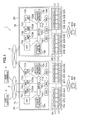
- Fig. 1 is a block diagram showing a hardware configuration for a storage system in an embodiment.
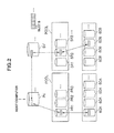
- Fig. 2 is a conceptual diagram illustrating logical volumes in the embodiment.
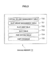
- Fig. 3 is a block diagram showing the content of shared memory in the embodiment.
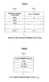
- Fig. 4 is a diagram showing a virtual volume management table in the embodiment.
- Fig. 5 is a diagram showing a slot group management table in the embodiment.
- Fig. 6 is a diagram showing a slot grid table in embodiment.
- Fig. 7 is a diagram showing a slot table in the embodiment.
- Fig. 8 is a diagram showing a pair setting table in the embodiment.
- Fig. 9 is a diagram illustrating a bitmap table in the embodiment.
- Fig. 10 is a flowchart showing processing for data transfer executed by a primary storage apparatus in a first pair setting in the embodiment.
- Fig.11 is a diagram showing transmission information in the case where copy data is sent in the embodiment.
- Fig. 12 is a diagram showing transmission information used when a "data unallocated" message in the embodiment is sent.
- Fig. 13 is a flowchart showing processing for data transfer executed by a secondary storage apparatus in a first pair setting in the embodiment.
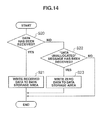
- Fig. 14 is a flowchart showing processing for data transfer executed by a secondary storage apparatus in a second pair setting in the embodiment.
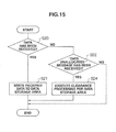
- Fig. 15 is a flowchart showing processing for quick format executed by a secondary storage apparatus in a second pair setting in the embodiment.
- Fig. 16 is a flowchart showing processing for data transfer executed by a primary storage apparatus in a third pair setting.
- numerical reference 1 represents the overall storage system in this embodiment.
- a host computer 2 is connected to a primary storage apparatus 5A via a network 3
- the primary storage apparatus 5A is connected to a secondary storage apparatus 5B via a data copy network 4.
- a storage apparatus that directly inputs/outputs data sent to/from the host computer 2 is referred to as a primary storage apparatus 5A.
- the host computer 2 is a computer device equipped with information processing resources such as a CPU and memory, and examples of the host computer 2 include a personal computer, a workstation, and a mainframe.
- the host computer 2 has information input devices such as a keyboard and a switch (not shown), and information output devices such as a monitor display and a speaker (not shown).
- Examples of the network 3 and the data copy network 4 include a SAN (Storage Area Network), a LAN (Local Area Network), the Internet, a public line, or a dedicated line. If the network 3 is a SAN, data is communicated according to Fibre Channel protocol. If the network 3 is a LAN, data is communicated according to TCP/IP protocol. In this embodiment, the network 3 for connecting the host computer 2 with the primary storage apparatus 5A is a SAN, and the other networks 3 and the copy network 4 are LANs.
- SAN Storage Area Network
- LAN Local Area Network
- the storage apparatus 5 has a disk unit 6 including plural hard disks 60 (HDD) and a controller unit 7 for managing the hard disks 60 in a RAID format.
- the suffixes "A” and “B” are omitted, except where the storage apparatuses have to be distinguished between.
- the hard disks 60 are expensive, high-access performance disks such as SCSI disks, or inexpensive, low-access performance disks such as SATA disks or optical disks.
- the controller unit 7 includes plural channel adapters 70 (referred to as “CHA” in the drawings), a switch 71, shared memory 72, cache memory 73, plural disk adapters 74 (referred to as “DKA” in the drawings), and a service processor 75 (referred to as “SVP” in the drawings).
- CHAIN channel adapters 70
- DKA cache memory
- SVP service processor
- Each channel adapter 70 is a microcomputer system including a microprocessor 700, memory (not shown), and a communication interface, and the like, and is provided with a port P for connection to a network. Each channel adapter 70 interprets various commands sent from the host computer 2 and executes the required processing. A network address (such as an IP address or WWN) for identifying each channel adapter 70 is allocated to the port P in the channel adapters 70. With this configuration, each channel adapter 70 can individually serve as a NAS (Network Attached Storage).
- NAS Network Attached Storage
- the switch 71 is connected to the channel adapters 70, the shared memory 72, the cache memory 73, and the disk adapters 74. Data and commands are exchanged, via the switch 71, between the channel adapters 70, the shared memory 72, the cache memory 73, and the disk adapters 74.
- the shared memory 72 is memory shared by the channel adapters 70 and the disk adapters 74.
- the shared memory 72 is used mainly for storing system configuration information, various control programs, and commands or similar sent from the host computer 2.
- the tables and program stored in the shared memory 72 will be described later.
- the cache memory 73 is also memory shared by the channel adapters 70 and the disk adapters 74.
- the cache memory 73 is used mainly for temporary storing data input to/output from the storage apparatuses.
- the disk adapter 74 is a microcomputer system including a microprocessor 700 (not shown) and memory (not shown), and the like, and functions as an interface for controlling protocols used during communication with the disk unit 6.
- Each disk adapter 74 is connected to a relevant disk unit 6 via, for example, a Fibre Channel cable, and exchanges data with that disk unit 6 in accordance with Fibre Channel protocol.
- the service processor 75 is a computer device for maintaining the storage apparatuses 5, and examples of the service processor 75 include a personal notebook computer.
- the service processor 75 is connected to the host computer 2 via the network 3, and is able to receive data or commands from the host computer 2.
- the storage navigator 8 is a computer device operated for managing the storage apparatuses 4, and examples of the storage navigator 8 include a personal computer.
- the storage navigator 8 sets storage apparatuses to be paired from among the plural storage apparatuses, sets a pair of virtual volumes V described later, and manages the association between a virtual volume V and a logical volume, which will also be described later.
- the storage navigator 8 may display the setting and management on a management screen 80.
- four disks in the hard disks 60 form a single RAID group.
- One or more logical volume(s) LU are defined in a storage area provided by the single RAID group.
- a specific identifier LUN (Logical Block Number) is allocated to each logical volume LU. Data is input or output by specifying an address, which is a combination of the identifier and a specific number LBA (Logical Block Address) assigned to each block, which is a logical division of a logical volume.
- LBA Logical Block Address
- Fig. 2 is a conceptual diagram showing a logical configuration for the hard disks 60 in the storage system 1.
- the logical volumes LU include virtual volumes V, which are logical volumes accessed by the host computer 2, and real volumes R, which are associated with those virtual volumes V.
- Each storage area in the real volumes R is associated with a real storage area in the hard disks 60.
- a pool area POOL is formed with plural real volumes R.
- Storage areas are provided to the virtual volumes V by dynamically allocating, to the virtual volumes V, storage areas in the real volumes R in the pool area POOL. Since the virtual volumes V do not have physical presence of volumes, when data is stored in response to a write request or similar from a host computer 2, a storage area in a real volume R included in a pool area POOL is reserved to store the data. If a read request from the host computer 2 is issued to an area that has reserved no storage area in a real volume R in the pool area POOL, the virtual volume V reads zero data from the pool area POOL to respond to the host computer 2. Thus a volume having an arbitrary capacity that does not depend on the physical capacity can be provided to the host computer 2 by virtually creating a volume capacity of the virtual volume V.
- Each storage area in the virtual volumes V and real volumes R is partitioned by a storage area referred to as a "slot S."
- the virtual volumes V and the real volumes R are associated with each other in units of slots S.
- a slot S is a minimum storage area where the above described data is stored, and corresponds to the above mentioned block.
- This embodiment aims at not only setting a pair of two virtual volumes V, but also setting a pair of a virtual volume V and a real volume R.
- a virtual volume V directly accessed by the host computer 2 is referred to as a "primary virtual volume V," and a copy destination virtual volume V where data stored in the primary virtual volume PV (in actuality, data in a storage area in the hard disks 60 allocated to the primary volume PV) is copied is referred to as a "secondary virtual volume SV.”
- a real volume associated with a primary virtual volume PV is referred to as a primary real volume PR
- a real volume associated with a secondary virtual volume SV is referred to as a secondary real volume SR.
- the primary and secondary storage apparatuses 5A and 5B respectively hold each of the below tables.
- the suffixes A and B are not used except where the tables are specified.
- Fig. 3 shows an example of various tables and a program stored in the shared memory 72.
- the shared memory 72 stores a virtual volume management table 720, a slot group management table 721, a slot grid table 722, a slot table 723, a pair setting table 724, and a copy program 725.
- the virtual volume management table 720, the slot group management table 721, the slot grid table 722, and the slot table 723 are association information used to associate, aside from the pair setting, storage areas of a virtual volume V and a real volume R in a storage apparatus 5.
- the copy program 725 is a program for having the storage apparatus 5 form a copy pair and execute copying.
- the virtual volume management table 720 is a table where storage areas of virtual volumes and associated slot numbers are stored.
- the virtual volume management table 720 includes "virtual volume address" entries 7200 and "slot number" entries 7201.
- the virtual volume management table 720 holds slot numbers "3-10,” which are associated with a virtual volume address "0x10.”
- the slot group management table 721 is a table for managing plural slots by groups, and includes "slot number group" entries 7210.
- the slot group management table 721 in Fig. 5 indicates that plural slots are managed in groups of fifty. Accordingly, the slot numbers "3-10" are managed in the first line of the slot group management table 721.
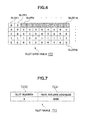
- the slot grid table 722 is a table showing, in a grid, plural slot numbers respectively managed in each line in the slot group management table 721. For example, if slots are managed in groups of fifty in the slot group management table 721, slots #1 to #50 are managed in one slot grid table 722, and the subsequent slots #51-#100 are managed in another slot grid table 722.
- a slot is associated with a virtual volume, "1,” which means "an allocated area,” is held. Meanwhile, if a slot is not associated with a virtual volume, "0,” which means "an unallocated area,” is held.
- slot numbers "3-10" are unallocated areas ("1").
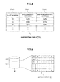
- the slot table 723 is a table prepared for each slot number, and stores a real volume address allocated to an arbitrary slot number.
- the slot table 723 includes a "slot number" entry 7230 and a "real volume address” entry 7231.
- the slot table 723 in Fig. 7 holds real volume address "0000,” which is allocated to slot number "3.”
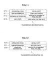
- Pair setting table 724 is a table for managing settings for pairs of copy source storage areas and copy destination storage areas.
- the pair setting table 724 includes "slot number" entries 7240, "copy source address” entries 7241, and "copy destination address” entries 7242.
- the pair setting table 724 shown in Fig. 8 holds primary and secondary storage areas associated with slot number "3.” Each of those primary and secondary storage areas is associated with address "0x10.”
- bitmap table M is management information that reflects the status of storage areas DS (hereinafter referred to as data storage areas DS) where data in real volumes R is stored, and is partitioned like a grid for management.
- the bitmap table M is a table used for real volumes that are not associated with Virtual volumes V.
- a slot number is allocated to each entry in the grid of the bitmap table M.
- the bitmap table M is stored in a management storage area MS for storing management information about real volumes R.
- the bitmap table has been explained as being managed in units of slots, but may also be managed in units other than slots, such as pages or blocks in the virtual volumes.
- the microprocessor 700A After receiving a remote copy order from the host computer 2 or the storage navigator 8A, the microprocessor 700A refers to the bitmap table M and checks whether or not the first slot S in the primary virtual volume PV has already been allocated (S1). In other words, the microprocessor 700A checks whether or not data is stored in the primary real volume associated with the primary virtual volume PV. When doing so, the microprocessor 700A checks whether or not the above described virtual volume management table 720A, slot group management table 721A, slot grid table 722A, and slot table 723A have been allocated to a copy target slot S.
- the microprocessor 700A judges the copy target slot S as having already been allocated (S1 : Yes)
- the data is stored in the primary real volume PR, so the microprocessor 700A reads data from the address in the primary real volume PR associated with the primary virtual volume PV (S2).
- the address in the associated primary real volume PR is searched for in the above described slot table 723.
- the microprocessor 700A refers to the pair setting table 724 and sends the above read data to the pair target secondary virtual volume SV (S3).
- the transmission information SI1 contains "operation code” SI10 for notifying the secondary storage apparatus 58 of an initial copy, "sub-information” SI11 for notification of whether or not copy data exists, "address information” SI12 about a copy source address, and "user data” SI13.
- step S3 Since in step S3 copy data is sent, "copy data exists" is registered as the "sub-information" SI11.
- address information SI12
- the head slot number in the primary real volume PV which is the position to start the copy, is held.
- Data for 1 slot S is registered as "user data” SI13.
- the microprocessor 700A judges the copy target slot S as being unallocated (S1 : NO), data is not stored in the primary real volume PR, so the microprocessor 700A sends, to the secondary storage apparatus 5B, a "data unallocated" message, which indicates no data stored in the storage area (slot S) in the copy target primary virtual volume PV (S4).
- the transmission information SI2 which is the notification message for "unallocated data," contains "operation code” SI20, "sub-information” S121, and "address information” S122, which is information on a copy source address.
- step S4 copy data is not sent; only a message is sent, so "no copy data" is held as the "sub-information" SI21.
- the head slot number in the primary real volume PV for which whether or not data is stored has been checked is held as the "address information" SI22.
- microprocessor 700A checks whether or not all slots S have been allocated (S5), If not all slots S have been checked (S5 : NO), the processing in steps S1 to S4 is repeated for the subsequent check target slots S.
- the microprocessor 700A terminates the processing for data transfer in the primary storage apparatus 5A.
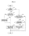
- the microprocessor 700B judges the data as having been received from the primary storage apparatus 5A (S10 : Yes), the microprocessor 700B refers to the pair setting table 724 and searches for the copy target secondary virtual volume SV. After that, the microprocessor 7008 refers to the bitmap table M and checks whether or not each slot S in the above searched secondary virtual volume SV has already been allocated to a secondary real volume SR (S11). In this step, the microprocessor 700B checks whether or not the above described virtual volume management table 720B, slot group management table 721B, slot grid table 722B, and slot table 723B have been allocated to a copy target slot S.
- each slot S in the secondary virtual volume SV searched for by the microprocessor 700B has not been allocated to a secondary real volume SR (S11 : NO)
- no data is stored in the secondary real volume SR, so a data storage area DS is reserved in the secondary real volume SR (S12).
- the microprocessor 700B sets, in the virtual volume management table 720B, the slot group management table 721B, the slot grid table 722B, and the slot table 723B, the relationship between the above reserved storage area in the secondary real volume SR and the secondary virtual volume SV.
- the microprocessor 700B writes the received data to the reserved data storage area DS in the secondary real volume SR (S13), and terminates the processing for data transfer.
- the microprocessor 7008 writes the received data to the data storage area DS in the associated secondary real volume SR (S13), and terminates the processing for data transfer.
- step S10 if the microprocessor 700B has not received data from the primary storage apparatus 5A (S10 : NO) but received a "data unallocated" message (S14 : Yes), the microprocessor 700B refers to the pair setting table 724 and searches for the copy target secondary virtual volume SV. After that, the microprocessor 700B refers to the virtual volume management table 720B, the slot group management table 721B, the slot grid table 722B, and the slot table 723B, and checks whether or not each slot S in the above searched secondary virtual volume SV has already been allocated to a secondary real volume SR (S15).
- the microprocessor 700B If each slots S in the secondary virtual volume SV searched for by the microprocessor 700B has already been allocated (S15 : Yes), the microprocessor 700B writes zero data to the data storage area DS in the associated real volume SR (S16) and terminates the processing for data transfer.
- the storage system 1 can create a virtual volume V having a capacity larger than the capacity of each real volume R. Accordingly, a large-capacity virtual volume V can be prepared in advance in consideration of the volume capacity that will increase in the future.
- the primary storage apparatus 5A For an unallocated area in a primary virtual volume PV, the primary storage apparatus 5A only has to transfer a "data unallocated" message to the secondary storage apparatus 5B, so processing relating to data transfer for that allocated area in the secondary storage apparatus 5B is unnecessary. Accordingly, as a whole, transfer time and processing time in the secondary storage apparatus 5B is greatly reduced.
- the microprocessor 700B checks, from the transmission information SI1 given from the primary storage apparatus 5A, that data has been received (S20 : Yes), the microprocessor 700B refers to the pair setting table 724B and searches for a copy target secondary real volume SR.
- the microprocessor 700B writes the received data to the data storage area DS indicated by an address in the above searched secondary real volume SR (S21), and terminates the processing for data transfer.
- step S20 if the microprocessor 700B checks, from the transmission information SI2 given from the primary storage apparatus 5A, that data has not been received (S20 : NO) but a "data unallocated" message has been received (S22 : Yes), the microprocessor 700B writes zero data to the data storage area DS indicated by an address in the above searched secondary real volume SR (S23) and terminates the processing for data transfer.
- the secondary storage apparatus 5B may execute "quick format” processing.
- the "quick format” processing is processing for erasing data in a data storage area DS in the secondary real volume SR.
- step S20 if the microprocessor 700B checks, from the transmission information SI2 given from the primary storage apparatus 5A, that data has not been received (S20 : NO) but a "data unallocated" message has been received (S22 : Yes), the microprocessor 700B erases data stored in the data storage area in the secondary real volume SR (S24). When doing so, the microprocessor 7008 sets the target slot S in the bitmap table M stored in the secondary real volume SR to "0.”
- microprocessor 700B terminates the processing for data transfer.
- the primary storage apparatus 5A since a virtual volume V is set as a primary volume and a real volume R is set as a secondary volume to form a pair, the primary storage apparatus 5A only has to transfer, regarding an unallocated area in a primary virtual volume PV, a "data unallocated" message to a secondary storage apparatus 5B.
- the secondary storage apparatus 5B only has to write zero data to the data storage area DS in the above set pair, so processing relating to data transfer is unnecessary. Accordingly, as a whole, transfer time can be reduced.
- the microprocessor 700A reads, after receiving a remote copy order from the host computer 2 or the storage navigator 8A, the bitmap table M from a management storage area MS in the primary real volume PR, and checks whether or not the first copy target slot S in the primary real volume PR is "0" (S30). More specifically, the microprocessor 700A checks whether or not data is stored in the data storage area DS at the position of the first slot S.
- the microprocessor 700A determines that the first copy target slot S is "0" (S30 : Yes)
- the microprocessor 700A sends a "data unallocated” message as transmission information SI2 to the secondary storage apparatus 5B (S31).
- microprocessor 700A determines that data exists in the data storage area DS corresponding to the first copy target slot S (S30 :
- the microprocessor 700A checks, for all slots, whether or not each slot S has been allocated (S34). If not all slots S have been checked (S34 :
- the microprocessor 700A If the microprocessor 700A has checked the allocation status of all slots S (S34 : NO), the microprocessor 700A terminates the processing for data transfer in the primary storage apparatus 5A.
- the primary storage apparatus 5A searches for an area in the primary real volume PR where data is not stored, and the primary storage apparatus 5A only has to transfer, regarding the area where data is not stored, a "'data unallocated' message" to a secondary storage apparatus 5B. Since the secondary storage apparatus 5B only has to write zero data to a data storage area DS in paired volumes, processing for data transfer is unnecessary and transfer time is reduced.
- the invention can be widely used in storage systems having one or more storage apparatus(es), or other types of storage systems.
Landscapes
- Engineering & Computer Science (AREA)
- Theoretical Computer Science (AREA)
- Human Computer Interaction (AREA)
- Physics & Mathematics (AREA)
- General Engineering & Computer Science (AREA)
- General Physics & Mathematics (AREA)
- Information Retrieval, Db Structures And Fs Structures Therefor (AREA)
Applications Claiming Priority (1)
| Application Number | Priority Date | Filing Date | Title |
|---|---|---|---|
| JP2008046724A JP5317495B2 (ja) | 2008-02-27 | 2008-02-27 | ストレージシステム、コピー方法及び正側のストレージ装置 |
Publications (2)
| Publication Number | Publication Date |
|---|---|
| EP2096529A2 true EP2096529A2 (fr) | 2009-09-02 |
| EP2096529A3 EP2096529A3 (fr) | 2011-04-06 |
Family
ID=40677537
Family Applications (1)
| Application Number | Title | Priority Date | Filing Date |
|---|---|---|---|
| EP08171196A Withdrawn EP2096529A3 (fr) | 2008-02-27 | 2008-12-10 | Système de stockage, procédé de copie, et appareil de stockage principal |
Country Status (4)
| Country | Link |
|---|---|
| US (2) | US8127102B2 (fr) |
| EP (1) | EP2096529A3 (fr) |
| JP (1) | JP5317495B2 (fr) |
| CN (1) | CN101520713B (fr) |
Families Citing this family (6)
| Publication number | Priority date | Publication date | Assignee | Title |
|---|---|---|---|---|
| JPH0664405B2 (ja) | 1984-07-13 | 1994-08-22 | キヤノン株式会社 | 転写装置 |
| JP5317495B2 (ja) | 2008-02-27 | 2013-10-16 | 株式会社日立製作所 | ストレージシステム、コピー方法及び正側のストレージ装置 |
| CN102246135B (zh) * | 2008-11-07 | 2015-04-22 | 戴尔康佩伦特公司 | 数据存储系统的瘦导入 |
| JP5540636B2 (ja) * | 2009-10-02 | 2014-07-02 | 日本電気株式会社 | ストレージシステム、ストレージ装置、ストレージ装置の記憶内容複製方法およびプログラム |
| US9965224B2 (en) * | 2010-02-24 | 2018-05-08 | Veritas Technologies Llc | Systems and methods for enabling replication targets to reclaim unused storage space on thin-provisioned storage systems |
| JP2016212548A (ja) * | 2015-05-01 | 2016-12-15 | 富士通株式会社 | ストレージ制御装置、ストレージ制御方法、及びストレージ制御プログラム |
Citations (3)
| Publication number | Priority date | Publication date | Assignee | Title |
|---|---|---|---|---|
| JPH1185408A (ja) | 1997-09-12 | 1999-03-30 | Hitachi Ltd | 記憶制御装置 |
| JP2003015915A (ja) | 2001-07-05 | 2003-01-17 | Hitachi Ltd | 記憶装置の容量自動拡張方法 |
| JP2008046724A (ja) | 2006-08-11 | 2008-02-28 | Dainippon Printing Co Ltd | 管理システム、サーバ及びプログラム |
Family Cites Families (5)
| Publication number | Priority date | Publication date | Assignee | Title |
|---|---|---|---|---|
| JP2006127028A (ja) | 2004-10-27 | 2006-05-18 | Hitachi Ltd | 記憶システム及び記憶制御装置 |
| JP4955996B2 (ja) * | 2005-09-20 | 2012-06-20 | 株式会社日立製作所 | ボリューム移行方法およびストレージネットワークシステム |
| JP4942371B2 (ja) | 2006-03-23 | 2012-05-30 | 株式会社日立製作所 | 記憶システム及びデータ管理方法 |
| JP4835249B2 (ja) | 2006-04-26 | 2011-12-14 | 株式会社日立製作所 | ストレージシステム、リモートコピー、その管理方法 |
| JP5317495B2 (ja) | 2008-02-27 | 2013-10-16 | 株式会社日立製作所 | ストレージシステム、コピー方法及び正側のストレージ装置 |
-
2008
- 2008-02-27 JP JP2008046724A patent/JP5317495B2/ja not_active Expired - Fee Related
- 2008-04-30 US US12/112,478 patent/US8127102B2/en not_active Expired - Fee Related
- 2008-12-10 EP EP08171196A patent/EP2096529A3/fr not_active Withdrawn
-
2009
- 2009-01-19 CN CN2009100048353A patent/CN101520713B/zh not_active Expired - Fee Related
-
2011
- 2011-11-15 US US13/296,461 patent/US8316205B2/en not_active Expired - Fee Related
Patent Citations (3)
| Publication number | Priority date | Publication date | Assignee | Title |
|---|---|---|---|---|
| JPH1185408A (ja) | 1997-09-12 | 1999-03-30 | Hitachi Ltd | 記憶制御装置 |
| JP2003015915A (ja) | 2001-07-05 | 2003-01-17 | Hitachi Ltd | 記憶装置の容量自動拡張方法 |
| JP2008046724A (ja) | 2006-08-11 | 2008-02-28 | Dainippon Printing Co Ltd | 管理システム、サーバ及びプログラム |
Also Published As
| Publication number | Publication date |
|---|---|
| US8316205B2 (en) | 2012-11-20 |
| CN101520713A (zh) | 2009-09-02 |
| EP2096529A3 (fr) | 2011-04-06 |
| JP5317495B2 (ja) | 2013-10-16 |
| CN101520713B (zh) | 2013-09-04 |
| JP2009205415A (ja) | 2009-09-10 |
| US20090216972A1 (en) | 2009-08-27 |
| US20120059987A1 (en) | 2012-03-08 |
| US8127102B2 (en) | 2012-02-28 |
Similar Documents
| Publication | Publication Date | Title |
|---|---|---|
| US8099569B2 (en) | Storage system and data migration method | |
| JP5222617B2 (ja) | 情報システム及びi/o処理方法 | |
| US8352678B2 (en) | Storage controller | |
| US8473703B2 (en) | Storage system and management method of the storage system | |
| US9122415B2 (en) | Storage system using real data storage area dynamic allocation method | |
| US7853765B2 (en) | Storage system and data management method | |
| US20120144116A1 (en) | Storage apparatus and storage area allocation method | |
| US20110264877A1 (en) | Storage subsystem and its data processing method, and computer system | |
| US7660946B2 (en) | Storage control system and storage control method | |
| US8316205B2 (en) | Storage system, copy method, and primary storage apparatus | |
| US8762671B2 (en) | Storage apparatus and its control method | |
| JP2013069096A (ja) | 制御装置、制御方法およびストレージ装置 | |
| JP5159353B2 (ja) | 記憶システム、解除方法及び副側のストレージ装置 | |
| US7966448B2 (en) | Storage apparatus and data writing method | |
| US7774543B2 (en) | Storage system, method for managing the same, and storage controller | |
| US20070245113A1 (en) | Storage system and data storage method | |
| US7493443B2 (en) | Storage system utilizing improved management of control information | |
| US20070118690A1 (en) | Storage system, disk array apparatus, volume presentation method, and data consistency confirmation method | |
| JP2009294699A (ja) | ストレージ装置 |
Legal Events
| Date | Code | Title | Description |
|---|---|---|---|
| PUAI | Public reference made under article 153(3) epc to a published international application that has entered the european phase |
Free format text: ORIGINAL CODE: 0009012 |
|
| AK | Designated contracting states |
Kind code of ref document: A2 Designated state(s): AT BE BG CH CY CZ DE DK EE ES FI FR GB GR HR HU IE IS IT LI LT LU LV MC MT NL NO PL PT RO SE SI SK TR |
|
| AX | Request for extension of the european patent |
Extension state: AL BA MK RS |
|
| PUAL | Search report despatched |
Free format text: ORIGINAL CODE: 0009013 |
|
| AK | Designated contracting states |
Kind code of ref document: A3 Designated state(s): AT BE BG CH CY CZ DE DK EE ES FI FR GB GR HR HU IE IS IT LI LT LU LV MC MT NL NO PL PT RO SE SI SK TR |
|
| AX | Request for extension of the european patent |
Extension state: AL BA MK RS |
|
| 17P | Request for examination filed |
Effective date: 20111006 |
|
| AKX | Designation fees paid |
Designated state(s): AT BE BG CH CY CZ DE DK EE ES FI FR GB GR HR HU IE IS IT LI LT LU LV MC MT NL NO PL PT RO SE SI SK TR |
|
| STAA | Information on the status of an ep patent application or granted ep patent |
Free format text: STATUS: THE APPLICATION HAS BEEN WITHDRAWN |
|
| 18W | Application withdrawn |
Effective date: 20161208 |