EP2096636B1 - Dispositif de lecture optique - Google Patents
Dispositif de lecture optique Download PDFInfo
- Publication number
- EP2096636B1 EP2096636B1 EP07806863A EP07806863A EP2096636B1 EP 2096636 B1 EP2096636 B1 EP 2096636B1 EP 07806863 A EP07806863 A EP 07806863A EP 07806863 A EP07806863 A EP 07806863A EP 2096636 B1 EP2096636 B1 EP 2096636B1
- Authority
- EP
- European Patent Office
- Prior art keywords
- region
- pickup device
- optical pickup
- dividing
- light source
- Prior art date
- Legal status (The legal status is an assumption and is not a legal conclusion. Google has not performed a legal analysis and makes no representation as to the accuracy of the status listed.)
- Expired - Fee Related
Links
- 230000003287 optical effect Effects 0.000 title claims abstract description 170
- 230000000737 periodic effect Effects 0.000 claims abstract description 60
- 238000000034 method Methods 0.000 claims description 17
- 239000011295 pitch Substances 0.000 description 13
- 102100030684 Sphingosine-1-phosphate phosphatase 1 Human genes 0.000 description 11
- 101710168942 Sphingosine-1-phosphate phosphatase 1 Proteins 0.000 description 11
- 102100030677 Sphingosine-1-phosphate phosphatase 2 Human genes 0.000 description 11
- 101710168938 Sphingosine-1-phosphate phosphatase 2 Proteins 0.000 description 11
- 238000001514 detection method Methods 0.000 description 11
- 238000009826 distribution Methods 0.000 description 5
- 230000000694 effects Effects 0.000 description 4
- 230000003321 amplification Effects 0.000 description 3
- 230000004048 modification Effects 0.000 description 3
- 238000012986 modification Methods 0.000 description 3
- 238000003199 nucleic acid amplification method Methods 0.000 description 3
- 230000007423 decrease Effects 0.000 description 2
- 238000010586 diagram Methods 0.000 description 2
- 239000004065 semiconductor Substances 0.000 description 2
- 101100532584 Clostridium perfringens (strain 13 / Type A) sspC1 gene Proteins 0.000 description 1
- 101100256651 Homo sapiens SENP6 gene Proteins 0.000 description 1
- 101100095550 Homo sapiens SENP7 gene Proteins 0.000 description 1
- 101150038317 SSP1 gene Proteins 0.000 description 1
- 101150098865 SSP2 gene Proteins 0.000 description 1
- 101100125020 Schizosaccharomyces pombe (strain 972 / ATCC 24843) pss1 gene Proteins 0.000 description 1
- 101100018019 Schizosaccharomyces pombe (strain 972 / ATCC 24843) ssc1 gene Proteins 0.000 description 1
- 102100023713 Sentrin-specific protease 6 Human genes 0.000 description 1
- 102100031406 Sentrin-specific protease 7 Human genes 0.000 description 1
- 238000006073 displacement reaction Methods 0.000 description 1
- 238000004519 manufacturing process Methods 0.000 description 1
- 238000005549 size reduction Methods 0.000 description 1
- 238000009987 spinning Methods 0.000 description 1
Images







Classifications
-
- G—PHYSICS
- G11—INFORMATION STORAGE
- G11B—INFORMATION STORAGE BASED ON RELATIVE MOVEMENT BETWEEN RECORD CARRIER AND TRANSDUCER
- G11B7/00—Recording or reproducing by optical means, e.g. recording using a thermal beam of optical radiation by modifying optical properties or the physical structure, reproducing using an optical beam at lower power by sensing optical properties; Record carriers therefor
- G11B7/08—Disposition or mounting of heads or light sources relatively to record carriers
- G11B7/09—Disposition or mounting of heads or light sources relatively to record carriers with provision for moving the light beam or focus plane for the purpose of maintaining alignment of the light beam relative to the record carrier during transducing operation, e.g. to compensate for surface irregularities of the latter or for track following
- G11B7/0901—Disposition or mounting of heads or light sources relatively to record carriers with provision for moving the light beam or focus plane for the purpose of maintaining alignment of the light beam relative to the record carrier during transducing operation, e.g. to compensate for surface irregularities of the latter or for track following for track following only
- G11B7/0903—Multi-beam tracking systems
-
- G—PHYSICS
- G11—INFORMATION STORAGE
- G11B—INFORMATION STORAGE BASED ON RELATIVE MOVEMENT BETWEEN RECORD CARRIER AND TRANSDUCER
- G11B7/00—Recording or reproducing by optical means, e.g. recording using a thermal beam of optical radiation by modifying optical properties or the physical structure, reproducing using an optical beam at lower power by sensing optical properties; Record carriers therefor
- G11B7/08—Disposition or mounting of heads or light sources relatively to record carriers
- G11B7/09—Disposition or mounting of heads or light sources relatively to record carriers with provision for moving the light beam or focus plane for the purpose of maintaining alignment of the light beam relative to the record carrier during transducing operation, e.g. to compensate for surface irregularities of the latter or for track following
-
- G—PHYSICS
- G11—INFORMATION STORAGE
- G11B—INFORMATION STORAGE BASED ON RELATIVE MOVEMENT BETWEEN RECORD CARRIER AND TRANSDUCER
- G11B7/00—Recording or reproducing by optical means, e.g. recording using a thermal beam of optical radiation by modifying optical properties or the physical structure, reproducing using an optical beam at lower power by sensing optical properties; Record carriers therefor
- G11B7/12—Heads, e.g. forming of the optical beam spot or modulation of the optical beam
- G11B7/135—Means for guiding the beam from the source to the record carrier or from the record carrier to the detector
- G11B7/1353—Diffractive elements, e.g. holograms or gratings
-
- G—PHYSICS
- G11—INFORMATION STORAGE
- G11B—INFORMATION STORAGE BASED ON RELATIVE MOVEMENT BETWEEN RECORD CARRIER AND TRANSDUCER
- G11B7/00—Recording or reproducing by optical means, e.g. recording using a thermal beam of optical radiation by modifying optical properties or the physical structure, reproducing using an optical beam at lower power by sensing optical properties; Record carriers therefor
- G11B2007/0003—Recording, reproducing or erasing systems characterised by the structure or type of the carrier
- G11B2007/0006—Recording, reproducing or erasing systems characterised by the structure or type of the carrier adapted for scanning different types of carrier, e.g. CD & DVD
Definitions
- the invention relates to an optical pickup device that is used in an optical information processor for performing processing such as recording of information onto an optical information recording medium and playback or erasure of information recorded on the optical information recording medium.
- Reading recorded information from an optical information recording medium is conducted by converging a light beam emitted from a light source such as a semiconductor laser device on a recording track of the optical disc by using an objective lens and converting reflected light from the optical disc to an electric signal by a photodetector.
- a focus error signal and a tracking error signal are detected and the position of the objective lens is controlled according to surface displacement, eccentricity, and the like of the optical disc.
- a differential push-pull (DPP) method is known as a typical method for detecting a tracking error signal.
- DPP differential push-pull
- a light beam is separated into three beams: a main beam; a + 1 st order diffracted beam; and a -1 st order diffracted beam. These three beams are respectively converged on three adjacent guide grooves formed at a prescribed pitch on the optical disc.
- Push-pull signals respectively obtained by detecting reflected light of the three beams and performing an arithmetic operation have a phase difference of 180 degrees between the main beam and the +1 st and -1 st order diffracted beams.
- optical discs such as a write once type DVD-R (Recordable) and an erasable type DVD-RW (Disk ReWritable) have a guide groove pitch of 0.74 ⁇ m
- optical discs such as an erasable type DVD-RAM (Random Access Memory) has a guide groove pitch of 1.23 ⁇ m.
- An optical pickup device that enables recording and playback of two or more types of optical discs of different standards has been demanded. The following optical pickup device is proposed in view of this demand (e.g., see Patent document 2).
- a special diffraction grating for separating a light beam is divided into three regions, and the phase of grating grooves periodically provided in each region is sequentially shifted by 90 degrees.
- a tracking error detection method using such a special diffraction grating is called an in-line DPP method, and the in-line DPP method enables stable tracking error detection on a plurality of optical information recording media having different guide groove pitches.
- a conventional optical pickup device using the conventional in-line DPP method has the following problems.
- FIG. 18 shows convergence spots of light beams that are converged on an optical information recording medium by a conventional optical pickup device.
- a convergence spot 101 corresponding to a +1 st order diffracted beam has higher intensity on the right side in a radial direction X of the optical information recording medium and has lower intensity on the left side.
- a convergence spot 102 corresponding to a -1 st order diffracted beam has lower intensity on the right side and has higher intensity on the left side. This can be explained as follows:
- the phase of grating grooves 119a in a region 119 is ahead of that of grating grooves 120a in a central region 120 by 90 degrees, and the phase of grating grooves 121a in a region 121 is behind that of the grating grooves 120a in the central region 120 by 90 degrees.
- the phase of the +1 st order diffracted beam that has passed through the region 119 is ahead of that of the +1 st order diffracted beam that has passed through the central region 120 by 90 degrees
- the phase of the +1 st order diffracted beam that has passed through the region 121 is behind that of the +1 st order diffracted beam that has passed through the central region 120 by 90 degrees.
- the phase relation of the grating grooves and diffracted beams is opposite for the -1 st order diffracted beam.
- phase of the -1 st order diffracted beam that has passed through the region 119 is behind that of the -1 st order diffracted beam that has passed through the central region 120 by 90 degrees
- the phase of the -1 st order diffracted beam that has passed through the region 121 is ahead of that of the -1 st order diffracted beam that has passed through the central region 120 by 90 degrees.
- the +1 st order diffracted beam has larger intensity distribution on the region 121 side where the phase is retarded, and the convergence spot 101 corresponding to the +1 st order diffracted beam on the optical information recording medium has higher intensity on the right side and lower intensity on the left side.
- the -1 st order diffracted beam has larger intensity distribution on the region 119 side where the phase is retarded, and the convergence spot 102 corresponding to the -1 st order diffracted beam has lower light intensity on the right side and higher intensity on the left side.
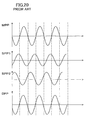
- FIG. 20 shows signal waveforms of a DPP signal obtained by the above convergence spots.
- the ordinate indicates signal strength and the abscissa indicates a relative position of the convergence spot on the optical information recording medium.
- MPP is a push-pull signal of a main beam corresponding to a 0 th order diffracted beam
- SPP1 is a push-pull signal of a preceding sub-beam corresponding to a +1 st order diffracted beam
- SPP2 is a push-pull signal of a succeeding sub-beam corresponding to a -1 st order diffracted beam
- DPP is a tracking error signal (differential push-pull signal) obtained from MPP, SPP1, and SPP2 as shown by the formula (1):
- DPP MPP - k ⁇ SPP ⁇ 1 + SPP ⁇ 2 where k is an arbitrary amplification factor. Since the respective convergence spots corresponding to the +1 st order diffracted beam and the -1 st order diffracted beam have left-right asymmetric intensity distribution, the phase difference of SSP1 and SSP2 from MPP is shifted from 180 degrees. If there is a signal strength difference between SPP1 and SPP2, DPP is shifted from a proper value and therefore each convergence spot cannot be formed on the same guide groove, hindering stable tracking error signal detection by the in-line DPP method. Note that, the positions where SPP1, SPP2, and DPP have proper values are shown by chain line in FIG. 20 .
- the invention is made to solve the above conventional problems and it is an object of the invention to implement an optical pickup device for conducting stable tracking error detection on a plurality of optical information recording media having different guide groove pitches while maintaining the advantages of the in-line DPP method.
- an optical pickup device of the invention includes a diffraction grating that is divided into four regions having different phases from each other.
- an optical pickup device is an optical pickup device for recording information onto an optical information recording medium and reading and erasing information recorded on the optical information recording medium.
- the optical pickup device includes: a light source; a diffraction grating for separating a light beam emitted from the light source into at least three light beams; and a photodetector for receiving the separated light beams reflected from the optical information recording medium.
- the diffraction grating is divided into a first region, a second region, a third region, and a fourth region having periodic structures of different phases by dividing lines extending in a direction parallel to a tangential direction of tracks of the optical information recording medium.
- the second region and the third region are located between the first region and the fourth region sequentially from the first region side.
- the periodic structure of the second region has a phase difference of approximately 180 degrees from the periodic structure of the third region
- the periodic structure of the first region has a phase difference of approximately 180 degrees from the periodic structure of the fourth region.
- the optical pickup device of the invention includes such a diffraction grating that the periodic structure of the second region has a phase difference of approximately 180 degrees from the periodic structure of the third region and the periodic structure of the first region has a phase difference of approximately 180 degrees from the periodic structure of the fourth region. Therefore, the phase of a + 1 st order diffracted beam that has passed through the first region is advanced with respect to that of the + 1 st order diffracted beam that has passed through the second region. The phase of the + 1 st order diffracted beam that has passed through the fourth region is advanced with respect to that of the +1 st order diffracted beam that has passed through the third region.
- the phase of the -1 st order diffracted beam is retarded in both cases. Accordingly, unlike the conventional in-line DPP method, spot shapes do not become left-right asymmetric, but the intensity distribution of convergence spots becomes left-right symmetric with respect to an extending direction of guide grooves.
- An optical pickup device for conducting stable tracking error detection on a plurality of optical information recording media having different guide groove pitches can thus be implemented.
- a distance between the dividing line dividing the first region and the second region from each other and the dividing line dividing the second region and the third region from each other is preferably equal to a distance between the dividing line dividing the second region and the third region from each other and the dividing line dividing the third region and the fourth region from each other.
- the light beams preferably include a 0 th order diffracted beam, a + 1 st order diffracted beam, and a -1 st order diffracted beam.
- a plurality of guide grooves are periodically formed on a recording surface of the optical information recording medium, and each of the light beams is converged on one of the plurality of guide grooves.
- the optical pickup device of the invention further includes an arithmetic processing circuit for detecting a tracking error signal by a differential push-pull method based on an output signal of the photodetector.
- the photodetector includes at least three light receiving elements respectively corresponding to the reflected light beams, and each of the light receiving elements is divided into a plurality of light receiving regions.
- a center of the light beam emitted from the light source is preferably positioned in the second region or the third region.
- the light source includes a first light source and a second light source, and a straight line connecting a center of a light beam emitted from the first light source and a center of a light beam emitted from the second light source crosses at least one of the dividing line dividing the first region and the second region from each other, the dividing line dividing the second region and the third region from each other, and the dividing line dividing the third region and the fourth region from each other.
- the light source includes a first light source and a second light source, and a straight line connecting a center of a light beam emitted from the first light source and a center of a light beam emitted from the second light source crosses the dividing line dividing the second region and the third region from each other.
- the light source includes a plurality of light sources, and a center of at least one of light beams respectively emitted from the plurality of light sources is positioned in the second region or the third region.
- the periodic structure of the first region of the diffraction grating preferably has a phase difference of 10 degrees to 350 degrees from the periodic structure of the second region. More preferably, the periodic structure of the first region of the diffraction grating has a phase difference of approximately 90 degrees from the periodic structure of the second region.
- the optical pickup device of the invention further includes an objective lens for converging the at least three light beams onto a recording surface of the optical information recording medium as independent convergence spots, and a region of the diffraction grating on which a range of the emitted light beam corresponding to an effective beam diameter determined by an aperture diameter of the objective lens is incident is a region including the first region, the second region, the third region, and the fourth region.
- a sum of a width of the second region and a width of the third region is preferably in a range of 10% to 40% of the effective beam diameter.
- the invention can thus implement an optical pickup device for conducting stable tracking error detection on a plurality of optical information recording media having different guide groove pitches while maintaining the advantages of the in-line DPP method.
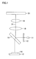
- FIG. 1 schematically shows a structure of an optical pickup device according to an embodiment of the invention.
- the optical pickup device of the embodiment includes a light source 11, such as a semiconductor laser element, for emitting a light beam 31 for performing recording of information onto an optical information recording medium 51 and playback of information recorded on the optical information recording medium 51, a diffraction grating 12 for diffracting and separating the light beam 31 into at least three light beams (not shown): a main beam that is a 0 th order diffracted beam; a sub-beam that is a +1 st order diffracted beam; and a sub-beam that is a -1 st order diffracted beam, a half mirror 15 for guiding the separated light beams 31 to the optical information recording medium 51, and an integrated circuit board 17 having a photodetector 16 for receiving the light beams 31 reflected from the optical information recording medium 51.
- a light source 11 such as a semiconductor laser element
- a collimating lens 18 and an objective lens 19 are placed between the half mirror 15 and the optical information recording medium 51.
- the light beam 31 emitted from the light source 11 is first diffracted and separated by the diffraction grating 12 into at least three light beams: a 0 th order diffracted beam; a +1 st order diffracted beam; and a -1 st order diffracted beam. These beams are then reflected by the half mirror 15 and reach the objective lens 19 through the collimating lens 18.
- the 0 th order diffracted beam, the +1 st order diffracted beam, and the -1 st order diffracted beam thus obtained by the diffraction grating 1 are then independently converged on a recording surface of the optical information recording medium 51 by the objective lens 19 to form three convergence spots.
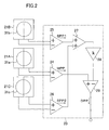
- FIG. 2 shows a circuit structure of the integrated circuit board 17 having the photodetector 16 in the optical pickup device of FIG. 1 .
- the integrated circuit board 17 has light receiving elements 21A, 21B, and 21C and an arithmetic processing circuit 23 for performing an arithmetic operation of signals from the light receiving elements.
- a main beam 31a and two sub-beams 31b and 31c separated from the emitted light beam 31 by the diffraction grating 12 are received by the light receiving elements 21A, 21B, and 21C, respectively.
- Each of the light receiving elements 21A, 21B, and 21C is divided into a plurality of light receiving regions.
- the arithmetic processing circuit 23 has subtracters 24, 25, and 26 for receiving signals from the light receiving elements 21A, 21B, and 21C, respectively, and an adder 27, an amplifier 28, and a subtracter 29 for receiving outputs from the subtracters 24, 25, and 26.
- the subtracters 24, 25, and 26 receive signals from the light receiving elements 21A, 21B, and 21C and output push-pull signals MPP, SPP1, and SPP2, respectively.
- the adder 27, the amplifier 28, and the subtracter 29 of the arithmetic processing circuit 23 will be described later.
- each light receiving element is divided into two light receiving regions. However, each light receiving element may be divided into three or more light receiving regions.
- each beam on each light receiving element is schematically shown to have a circular shape. However, the beam shape is not limited to this. When an astigmatic method is used for a focus error signal, each beam on each light receiving element is rotated by approximately 90 degrees. Each light receiving element therefore needs to be rotated by 90 degrees in advance in this case.
- the optical pickup device of this embodiment is characterized in the diffraction grating 12 for diffracting the light beam 31 emitted from the light source 11, and is characterized especially in a periodic structure of the diffraction grating 12.
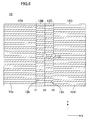
- FIG. 3 shows a periodic structure, that is, a grating pattern, of the diffraction grating 12.
- a grating surface of the diffraction grating 12 is divided into four regions: a first region 12A; a second region 12B; a third region 12C; and a fourth region 12D by three dividing lines D1, D2, and D3 extending in an extending direction of guide grooves of the optical information recording medium 51 (hereinafter, referred to as Y direction), that is, in a direction substantially parallel to a tangential direction of tracks of the optical information recording medium 51.
- the parallel direction means a parallel direction in view of an optical system provided between the diffraction grating 12 and the optical information recording medium 51.
- the first region 12A and the second region 12B are adjacent to each other with the dividing line D1 interposed therebetween.
- the second region 12B and the third region 12C are adjacent to each other with the dividing line D2 interposed therebetween.
- the third region 12C and the fourth region 12D are adjacent to each other with the dividing line D3 interposed therebetween.
- the first region 12A, the second region 12B, the third region 12C, and the fourth region 12D have grating grooves 12a, 12b, 12c, and 12d periodically provided along a radial direction of the optical information recording medium 51 (hereinafter, referred to as X direction), respectively.
- the grating grooves 12a, 12b, 12c, and 12d have the same width, and the portions (protruding portions) between the grating grooves 12a, 12b, 12c, and 12d have the same width.
- the phase of the periodic structure formed by the grating grooves 12a in the first region 12A is substantially 90 degrees ahead of that of the periodic structure formed in the second region 12B (a phase difference of substantially +90 degrees).
- the arrangement cycle of the grating grooves 12a in the first region 12A is shifted by quarter cycle from the arrangement cycle of the grating grooves 12b in the second region 12B in +Y direction.
- the phase of the periodic structure formed in the fourth region 12D is substantially 90 degrees behind that of the periodic structure formed in the second region 12B (a phase difference of substantially -90 degrees).
- the arrangement cycle of the grating grooves 12d in the fourth region 12D is shifted by quarter cycle from the arrangement cycle of the grating grooves 12b in the second region 12B in -Y direction.
- the periodic structure in the first region 12A has a phase difference of substantially 180 degrees from the periodic structure in the fourth region 12D.
- the phase of the periodic structure in the third region 12C is shifted by substantially 180 degrees from that of the periodic structure in the second region 12B.
- the arrangement cycle of the grating grooves 12c in the third region 12C is shifted by half cycle from the arrangement cycle of the grating grooves 12b in the second region 12B in +Y direction.
- phase difference of the periodic structure between the regions does not have to be exactly 90 degrees or 180 degrees. Since the convergence spots on the recording surface of the optical information recording medium 51 need only have a shape described below, the phase difference between regions may include an error of about ⁇ 10 degrees.
- the center (the center of a light emitting point) L1 of the light beam emitted from the light source 11 is positioned on the dividing line D2 within the assembly accuracy range of the device.
- the emitted light beam incident on the diffraction grating 12 is separated into a main beam and sub-beams having a prescribed phase difference by the respective periodic structures formed in the first region 12A, the second region 12B, the third region 12C, and the fourth region 12D.
- the main beam and the sub-beams are then guided to the optical information recording medium 51.
- optical pickup device of this embodiment can stably detect tracking errors on optical information recording media having different guide groove pitches.
- FIG. 4 shows the shapes of respective convergence spots of the main beam 31a and two sub-beams 31b and 31c of the emitted light beam which are generated by the diffraction grating 12 on the recording surface of the optical information recording medium 51.
- X direction shows the radius direction of the optical information recording medium
- Y direction shows the extending direction of the guide grooves.
- the diffraction grating in the second region 12B has a phase difference of 180 degrees from the diffraction grating in the third region 12C. Therefore, diffracted light that has passed through the second region 12B and diffracted light that has passed through the third region 12C cancel each other, and the respective convergence spots of the sub-beams 31b and 31c on the recording surface of the optical information recording medium 51 in FIG. 4 have lower intensity in the center. Since the respective convergence spots of the sub-beams 31b and 31c need only have lower intensity in the center, the phase difference between the second region 12B and the third region 12C may include an error of about ⁇ 10 degrees from 180 degrees.
- the phase of the diffraction grating in the first region 12A is 90 degrees ahead of that of the diffraction grating in the second region 12B.
- the phase of the diffraction grating in the fourth region 12D is 90 degrees ahead of that of the diffraction grating in the third region 12C. Accordingly, the phase of the +1 st order diffracted beam that has passed through the first region 12A is advanced by 90 degrees from that of the + 1 st order diffracted beam that has passed through the second region 12B.
- the phase of the +1 st order diffracted beam that has passed through the fourth region 12D is advanced by 90 degrees from that of the +1 st order diffracted beam that has passed through the third region 12C.
- phase of the -1 st order diffracted beam is retarded by 90 degrees. Accordingly, unlike the conventional in-line DPP method, spot shapes do not become left-right asymmetric, but the intensity distribution of the convergence spots becomes left-right symmetric with respect to Y direction.
- the phase difference between the first region 12A and the second region 12B and the phase difference between the fourth region 12D and the third region 12C may include an error of about ⁇ 10 degrees from 90 degrees.
- a plurality of guide grooves 51a are periodically formed on the recording surface of the optical information recording medium 51.
- the respective convergence spots of the main beam 31a, the sub-beam 31b, and the sub-beam 31c of the light beam 31 converged by the objective lens 19 are located on the same guide groove 51a, as shown in FIG. 4 .
- the main beam 31a, the sub beam 31b, and the sub beam 31c are reflected at the respective convergence spots, and the reflected light beams corresponding to the respective convergence spots are respectively received by the light receiving elements 21A, 21B, and 21C of the photodetector 16.
- the light receiving elements 21A, 21B, and 21C output a push-pull signal MPP corresponding to the main beam 31a, a push-pull signal SPP1 corresponding to the sub-beam 31b, and a push-pull signal SPP2 corresponding to the sub-beam 31c, respectively.
- Offset components of the push-pull signals MPP, SPP1, and SPP2 resulting from a radial shift of the objective lens 19 (a shift in the radius direction of the optical information recording medium) and a tilt of the optical information recording medium 51 are generated on the same side (the same phase) for each of the radial shift of the objective lens 19 and the tilt of the optical information recording medium 51. Accordingly, a differential push-pull (DPP) signal obtained by cancelling the offsets resulting from the radial shift of the objective lens 19 and the tilt of the optical information recording medium 51 can be detected by performing an arithmetic operation shown by the formula (2) by using the adder 27, the amplifier 28, and the subtracter 29 shown in FIG. 2 :
- DPP differential push-pull
- DPP MPP - k ⁇ SPP ⁇ 1 + SPP ⁇ 2 where k is an amplification factor of the amplifier 28.
- FIG. 5 shows respective output waveforms of the push-pull signals MPP, SPP1, and SPP2 and the DPP signal obtained by the formula (2).
- the ordinate indicates signal strength and the abscissa indicates a relative position of the convergence spot on the optical information recording medium 51.
- SPP1 and SPP2 have a phase difference of exactly 180 degrees from MPP. Even if there is a signal strength difference between SPP1 and SPP2, the DPP signal obtained by the formula (2) has a proper value and each convergence spot can therefore be formed on the same guide groove.
- the inputs of the adder 27 are respectively connected to the respective outputs of the subtracters 25 and 26, and the input of the amplifier 28 is connected to the output of the adder 27.
- the inputs of the subtracter 29 are respectively connected to the output of the subtracter 24 and the output of the amplifier 28.
- the arithmetic operation shown by the formula (2) can be performed with this structure.
- the coefficient k in the formula (2) is used to correct the difference in light intensity among the main beam 31a, the sub-beam 31b, and the sub-beam 31c that are reflected from the optical information recording medium 51.
- the coefficient k is a/2b.
- the coefficient k is a constant that is determined according to the type of the optical information recording medium 51. Note that a signal processing circuit having a conventional structure may be used in this embodiment.
- the optical information recording medium 51 is not limited to a specific type, and DVDs including a DVD-ROM, a DVD-RAM, a DVD-R, and a DVD-RW and CDs including a CD-ROM, a CD-R, and a CD-RW may be used as the optical information recording medium 51.
- the wavelength of the light beam 31 can be determined according to the type of the optical information recording medium 51, and is in the range of about 650 nm to about 780 nm in the case of a DVD and a CD.
- stable tracking error signal detection can be performed on both a DVD having a guide groove pitch of 0.74 ⁇ m such as a DVD-R and a DVD having a guide groove pitch of 1.23 ⁇ m such as a DVD-RAM.
- the diffraction grating 12 is placed between the light source 11 and the half mirror 15 in the optical system shown in FIG. 1 .
- the diffraction grating 12 may alternatively be placed, for example, between the half mirror 15 and the collimating lens 18.
- the optical system of FIG. 1 may be replaced with an optical system in which a light source and a photodetector are integrated (for example, an optical system that does not use a half mirror), and the diffraction grating may be placed between the light source and the collimating lens.
- the grating grooves in each region of the diffraction grating 12 are formed along X direction, that is, the radius direction of the optical information recording medium.
- the grating grooves may alternatively be formed in a direction oblique to X direction.
- the second region 12B and the third region 12C of the diffraction grating 12 have the same width.
- the second region 12B and the third region 12C of the diffraction grating 12 need not necessarily have the same width.
- a single light beam is emitted from the light source.
- the same effects can be obtained even when an optical pickup device has a plurality of light sources and a plurality of light beams are emitted from the light sources.
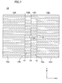
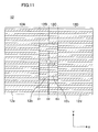
- the center L1 of a light emitting point of a first light source may be positioned on the dividing line D2 and the center L2 of a light emitting point of a second light source may be positioned on the dividing line D3 within the assembly accuracy range of the device.
- the center L1 of a light emitting point of a first light source may be positioned on the dividing line D2 and the center L2 of a light emitting point of a second light source may be positioned within the fourth region 12D near the dividing line D3 within the assembly accuracy range of the device.
- FIG. 7 the center L1 of a light emitting point of a first light source may be positioned on the dividing line D2 and the center L2 of a light emitting point of a second light source may be positioned within the fourth region 12D near the dividing line D3 within the assembly accuracy range of the device.
- the center L1 of a light emitting point of a first light source may be positioned within the second region 12B and the center L2 of a light emitting point of a second light source may be positioned within the third region 12C within the assembly accuracy range of the device.
- the center L1 of a light emitting point of a first light source may be positioned within the first region 12A near the dividing line D1 and the center L2 of a light emitting point of a second light source may be positioned within the fourth region 12D near the dividing line D3 within the assembly accuracy range of the device.
- the number of light sources is not limited to two, and three or more light sources may be provided.
- the center of a light emitting point of at least one light source is positioned within the second region 12B or the third region 12C within the assembly accuracy range of the device and the center of a light emitting point of the remainder of the light sources need not be specifically limited.
- the entire diffraction grating 12 is divided into the first region 12A, the second region 12B, the third region 12C, and the fourth region 12D.
- a region within an effective beam diameter range determined by the aperture diameter of the objective lens in the diffraction grating 12 need only be divided into the first to fourth regions, and the region outside the effective beam diameter range may have a different dividing state.
- the second region 12B and the second region 13B may not be formed in the region outside the effective beam diameter range.
- the phase difference between the periodic structures of the first region 12A and the periodic structure of the second region 12B is 90 degrees and the phase difference between the periodic structure of the fourth region 12D and the periodic structure of the third region 12C is 90 degrees.
- the phase difference between the first region 12A and the second region 12B and the phase difference between the third region 12C and the fourth region 12D may be any value as long as the phase difference between the first region 12A and the fourth region 12D is substantially 180 degrees and the phase difference between the second region 12B and the third region 12C is substantially 180 degrees.
- the phase difference between the first region 12A and the second region 12B and the phase difference between the fourth region 12D and the third region 12C are preferably in the range of 10 degrees and 350 degrees, and more preferably in the range of 70 degrees and 290 degrees.
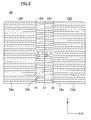
- FIG. 12 shows an example in which the phase difference between the first region 12A and the fourth region 12D is substantially 180 degrees, the phase difference between the second region 12B and the third region 12C is substantially 180 degrees, and the phase difference between the first region 12A and the second region 12B and the phase difference between the fourth region 12D and the third region 12C are substantially 45 degrees.
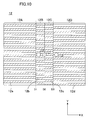
- FIG. 13 shows an example in which the phase difference between the periodic structure of the first region 12A and the periodic structure of the fourth region 12D is substantially 180 degrees, the phase difference between the periodic structure of the second region 12B and the periodic structure of the third region 12C is substantially 180 degrees, and the phase difference between the first region 12A and the second region 12B and the phase difference between the fourth region 12D and the third region 12C are substantially 180 degrees.
- the same effects as those of the diffraction grating of FIG. 3 can be obtained in these cases as well.
- FIGs. 14A through 14C show relations between the shift amount of the objective lens 19 and the DPP signal amplitude in the case where a DVD-RAM is used as the optical information recording medium 51.
- FIGs. 14A through 14C show examples in which the phase difference between the first region 12A and the second region 12B is 0 degrees, 90 degrees, and 180 degrees, respectively.
- the ordinate shows the DPP signal amplitude normalized assuming that the DPP signal amplification value is 100% when the shift amount of the objective lens 19 is 0 ⁇ m.
- the phase difference between the periodic structure of the first region 12A and the periodic structure of the fourth region 12D is substantially 180 degrees and the phase difference between the periodic structure of the second region 12B and the periodic structure of the third region 12C is substantially 180 degrees.
- the DPP signal amplitude changes more with shifting of the objective lens than in the case where the phase difference between the first region 12A and the second region 12B is 180 degrees.
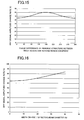
- FIG. 15 shows a relation between the phase difference between the first region 12A and the second region 12B and the change rate of DPP signal amplitude.
- the change rate of DPP signal amplitude is shown as a ratio of the DPP signal amplitude obtained when the shift amount of the objective lens is 300 ⁇ m to the DPP signal amplitude obtained when the shift amount of the objective lens is 0 ⁇ m.
- the change rate of DPP signal amplitude is closest to 100% when the phase difference between the periodic structure of the first region 12A and the periodic structure of the second region 12B is 180 degrees.
- the change rate of DPP signal amplitude decreases as the phase difference gets closer to 0 degrees or 360 degrees.
- the DPP signal amplitude is constant even if the objective lens is shifted. It is therefore more preferable that the change rate of DPP signal amplitude is closer to 100%.
- the phase difference between the periodic structure of the first region 12A and the periodic structure of the second region 12B can therefore be in the range of 10 degrees to 350 degrees. For more uniform DPP signal amplitude, however, it is preferable that the phase difference between the first region 12A and the second region 12B is in the range of 70 degrees to 290 degrees.
- a light beam that is effectively used includes a portion that has passed through the first region 12A of the diffraction grating 12, a portion that has passed through the second region 12B, a portion that has passed through the third region 12C, and a portion that has passed through the fourth portion 12D.
- a region of the diffraction grating 12 on which a range of the emitted light beam corresponding to the effective beam diameter determined by the aperture diameter of the objective lens 19 is incident includes the first region 12A through the fourth region 12D.
- the light source is a DVD-type light source
- the width W1 of the second region 12B and the width W2 of the third region 12C of the diffraction grating 12, that is, the width (W1 + W2) is in the range of 10% to 40% of the effective beam diameter determined by the aperture diameter of the objective lens 19.
- FIG 16 shows a relation between the change rate of DPP signal amplitude and the ratio of the width (W1 + W2) to the effective beam diameter determined by the aperture diameter of the objective lens 19 in a DVD-RAM.
- the change rate of DPP signal amplitude is shown as a ratio of the DPP signal amplitude obtained when the shift amount of the objective lens is 300 ⁇ m to the DPP signal amplitude obtained when the shift amount of the objective lens is 0 ⁇ m.
- the change rate of DPP signal amplitude is smaller than 66%.
- the DPP signal amplitude thus decreases by 34% or more of the DPP signal amplitude obtained when the shift amount of the objective lens is 0 ⁇ m. Such a large change in DPP signal amplitude is not preferable.
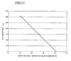
- FIG 17 shows a relation between the sum (SPP amplitude) of signal amplitude of the push-pull signal SPP1 and signal amplitude of the push-pull signal SPP2 and the ratio of the width (W1 + W2) to the effective beam diameter determined by the aperture diameter of the objective lens 19.
- the width (W1 + W2) is larger than 40% of the effective beam diameter determined by the aperture diameter of the objective lens 19
- the signal amplitude becomes closer to 0. Since the absolute value of the signal amplitude is reduced, characteristics of the optical pickup device are degraded.
- the width (W1 + W2) is in the range of 10% to 40% of the effective beam diameter determined by the aperture diameter of the objective lens.
- the width (W1 + W2) that is, the sum of the width W1 of the second region 12B and the width W2 of the third region 12C of the diffraction grating 12, is in the range of 10% to 35% of the DVD effective beam diameter determined by the aperture diameter of the objective lens 19.
- the optical pickup device of this embodiment can be used for various optical information recording media having different guide groove pitches and achieves tracking error signal detection that enables more stable recording and playback.
- the optical pickup device of this embodiment can implement size reduction, simplification, cost reduction, improved efficiency, and the like in DVD- and CD-type recording devices and playback devices.
- the optical pickup device of this embodiment is very useful as an optical pickup device having a signal detection function such as a playback signal, a recording signal, and various servo signals which are used in an optical head device that serves as a main part of an optical information processor for performing processing, such as recording, playback, and erasure of information, on an optical information recording medium such as an optical disc.
- the invention can implement an optical pickup device for performing stable tracking error detection on a plurality of optical information recording media having different guide groove pitches while maintaining the advantages of the in-line DPP method.
- the optical pickup device of the invention is useful as, for example, an optical pickup device that is used in an optical information processor for performing processing such as recording of information onto an optical information recording medium and playback or erasure of information recorded on an optical information recording medium.
Landscapes
- Physics & Mathematics (AREA)
- Optics & Photonics (AREA)
- Optical Head (AREA)
- Optical Recording Or Reproduction (AREA)
Abstract
Claims (22)
- Dispositif de lecture optique permettant d'enregistrer des informations sur un support optique d'enregistrement d'informations et de lire ainsi que d'effacer des informations enregistrées sur le support optique d'enregistrement d'informations, comprenant :une source de lumière (11)un réseau de diffraction (12) permettant de séparer un faisceau lumineux (31) émis depuis la source de lumière en au moins trois faisceaux lumineux, etun photodétecteur (16) permettant de recevoir les faisceaux lumineux séparés réfléchis à partir du support optique d'enregistrement d'informations (51),caractérisé en ce quele réseau de diffraction (12) est divisé en une première zone (12A), une deuxième zone (12B), une troisième zone (12C) et une quatrième zone (12D) comportant des structures périodiques de phases différentes l'une de l'autre obtenues en divisant des lignes de division s'étendant dans la direction parallèle à une direction tangentielle de pistes du support optique d'enregistrement d'informations,la deuxième zone et le troisième zone sont situées entre la première zone et la quatrième zone en séquence depuis le côté occupé par la première zone,la structure périodique de la deuxième zone présente une différence de phase d'approximativement 180 degrés par rapport à la structure périodique de la troisième zone, etla structure périodique de la première zone présente une différence de phase d'approximativement 180 degrés par rapport à la structure périodique de la quatrième zone.
- Dispositif de lecture optique selon la revendication 1, dans lequel un faisceau lumineux diffracté du 1e ordre qui a traversé la première zone (12A) présente une différence de phase de 80 degrés à 100 degrés par rapport à un faisceau lumineux diffracté du 1e ordre qui a traversé la deuxième zone (12B).
- Dispositif de lecture optique selon la revendication 1, dans lequel un faisceau lumineux diffracté du 1e ordre qui a traversé la première zone (12A) présente une différence de phase de 35 degrés à 55 degrés par rapport à un faisceau lumineux diffracté du 1e ordre qui a traversé la deuxième zone (12B).
- Dispositif de lecture optique selon la revendication 1, dans lequel le centre du faisceau lumineux émis depuis la source de lumière (11) est positionné dans la deuxième zone (12B) ou dans la troisième zone (12C).
- Dispositif de lecture optique selon la revendication 1, dans lequel la source de lumière inclut une première source de lumière et une seconde source de lumière.
- Dispositif de lecture optique selon la revendication 1 ou 5, dans lequel la distance entre la ligne de division (D1), qui sépare la première zone (12A) et la deuxième zone (12B) l'une de l'autre, et la ligne de division (D2), qui sépare la deuxième zone (12B) et la troisième zone (12C) l'une de l'autre, est égale à la distance entre la ligne de division (D2) qui sépare la deuxième zone et 1a troisième zone l'une de l'autre et la ligne de division (D3) qui sépare la troisième zone et la quatrième zone l'une de l'autre.
- Dispositif de lecture optique selon la revendication 1 ou 5, dans lequel les faisceaux lumineux (31) incluent un faisceau diffracté d'ordres 0 (31a), un faisceau lumineux diffracté du 1e ordre (31b) et un faisceau lumineux diffracté d'ordre -1 (31c).
- Dispositif de lecture optique selon la revendication 1 ou 5, dans lequel plusieurs rainures de guidage (51a) sont formées périodiquement sur une surface d'enregistrement du support optique d'enregistrement d'informations (51), et on fait converger chacun des faisceaux lumineux sur l'une de la pluralité de rainures de guidage.
- Dispositif de lecture optique selon la revendication 1 ou 5, comprenant en outre un circuit de traitement arithmétique (23) permettant de détecter un signal d'erreur de suivi de piste grâce à un procédé différentiel de type push-pull fondé sur le signal de sortie du photodétecteur.
- Dispositif de lecture optique selon la revendication 1 ou 5, dans lequel le photodétecteur (16) inclut au moins trois éléments de réception de lumière correspondant respectivement aux faisceaux lumineux réfléchis, et chacun des éléments de réception de lumière est divisé en une pluralité de zones de réception de lumière.
- Dispositif de lecture optique selon la revendication 5, dans lequel une ligne droite reliant le centre du faisceau lumineux émis depuis la première source de lumière et le centre du faisceau lumineux émis depuis la seconde source de lumière croise au moins l'une de la ligne de division (D1) qui sépare la première zone (12A) et la deuxième zone (12B) l'une de l'autre, de la ligne de division (D2) qui sépare la deuxième zone (12B) et la troisième zone (12C) l'une de l'autre et de la ligne de divisions (D3) qui sépare la troisième zone (12C) et la quatrième zone (12D) l'une de l'autre.
- Dispositif de lecture optique selon la revendication 5, dans lequel une ligne droite reliant le centre du faisceau lumineux émis depuis la première source de lumière et le centre d'un faisceau lumineux émis depuis la seconde source de lumière croise la ligne de division (D2) qui sépare la deuxième zone (12B) et la troisième zone (12C) l'une de l'autre.
- Dispositif de lecture optique selon la revendication 5, dans lequel le centre d'un faisceau lumineux émis depuis la première source de lumière est positionné approximativement sur la ligne de division (D2) qui sépare la deuxième zone (12B) et la troisième zone (12C) l'une de l'autre, et le centre d'un faisceau lumineux émis depuis la seconde source de lumière est positionné approximativement sur la ligne de division (D3) qui sépare la troisième zone (12C) et la quatrième zone (12D) l'une de l'autre.
- Dispositif de lecture optique selon la revendication 5, dans lequel le centre d'un faisceau lumineux émis depuis la première source de lumière est positionné approximativement sur la ligne de division (D2) qui sépare la deuxième zone (12B) et la troisième zone (12C) l'une de l'autre, et le centre d'un faisceau lumineux émis depuis la seconde source de lumière est positionné dans la quatrième zone (12D) à proximité de la ligne de division (D3) qui sépare la troisième zone (12C) et la quatrième zone (12D) l'une de l'autre.
- Dispositif de lecture optique selon la revendication 5, dans lequel le centre d'un faisceau lumineux émis depuis la première source de lumière est positionné dans la deuxième zone (12B), et le centre d'un faisceau lumineux émis depuis la seconde source de lumière est positionné dans la troisième zone (12C).
- Dispositif de lecture optique selon la revendication 5, dans lequel le centre d'un faisceau lumineux émis depuis la première source de lumière est positionné dans la première zone (12A) à proximité de la ligne de division (D1) qui sépare la première zone (12A) et la deuxième zone (12B) l'une de l'autre, et le centre d'un faisceau lumineux émis depuis la seconde source de lumière est positionné dans la quatrième zone (12D) à proximité de la ligne de division (D3) qui sépare la troisième zone (12C) et la quatrième zone (12D) l'une de l'autre.
- Dispositif de lecture optique selon la revendication 5, dans lequel le centre d'un faisceau lumineux émis depuis la première source de lumière est positionné approximativement sur la ligne de division (D2) qui sépare la deuxième zone (12B) et la troisième zone (12C) l'une de l'autre, et le centre d'un faisceau lumineux émis depuis la seconde source de lumière est positionné dans la troisième zone (12C) à proximité de la ligne de division (D3) qui sépare la troisième zone (12C) et la quatrième zone (12D) l'une de l'autre.
- Dispositif de lecture optique selon la revendication 1 ou 5, dans lequel la structure périodique de la première zone (12A) du réseau de diffraction présente une différence de phase de 10 degrés à 350 degrés par rapport à la structure périodique de la deuxième zone (12B).
- Dispositif de lecture optique selon la revendication 1 ou 5, dans lequel la structure périodique de la première zone (12A) du réseau de diffraction présente une différence de phase d'approximativement 90 degrés par rapport à la structure périodique de la deuxième zone (12B).
- Dispositif de lecture optique selon la revendication 1 ou 5, dans lequel la structure périodique de la première zone (12A) du réseau de diffraction présente une différence de phase d'approximativement 270 degrés par rapport à la structure périodique de la deuxième zone (12B).
- Dispositif de lecture optique selon la revendication 1 ou 5, comprenant en outre une lentille d'objectif (19) permettant de faire converger les au moins trois faisceaux lumineux sur une surface d'enregistrement du support optique d'enregistrement d'informations (51) comme des points de convergence indépendants, une zone du réseau de diffraction, sur laquelle est incidente une plage du faisceau lumineux émis, correspondant à un diamètre effectif de faisceau déterminé par un diamètre d'ouverture de la lentille d'objectif, incluant la première zone (12A), la deuxième zone (12B), la troisième zone (12C) et la quatrième zone (12D).
- Dispositif de lecture optique selon la revendication 21, dans lequel la somme de la largeur de la seconde zone (12B) et de la largeur de la troisième zone (12C) se trouve dans la plage de 10 % à 40 % du diamètre effectif du faisceau.
Applications Claiming Priority (3)
| Application Number | Priority Date | Filing Date | Title |
|---|---|---|---|
| JP2006339617 | 2006-12-18 | ||
| JP2007164510A JP4106072B1 (ja) | 2006-12-18 | 2007-06-22 | 光ピックアップ装置 |
| PCT/JP2007/067422 WO2008075484A1 (fr) | 2006-12-18 | 2007-09-06 | Dispositif de lecture optique |
Publications (3)
| Publication Number | Publication Date |
|---|---|
| EP2096636A1 EP2096636A1 (fr) | 2009-09-02 |
| EP2096636A4 EP2096636A4 (fr) | 2010-01-27 |
| EP2096636B1 true EP2096636B1 (fr) | 2012-06-27 |
Family
ID=39536120
Family Applications (1)
| Application Number | Title | Priority Date | Filing Date |
|---|---|---|---|
| EP07806863A Expired - Fee Related EP2096636B1 (fr) | 2006-12-18 | 2007-09-06 | Dispositif de lecture optique |
Country Status (7)
| Country | Link |
|---|---|
| US (2) | US7751297B2 (fr) |
| EP (1) | EP2096636B1 (fr) |
| JP (1) | JP4106072B1 (fr) |
| KR (1) | KR20090092693A (fr) |
| CN (1) | CN101473375B (fr) |
| TW (1) | TW200828291A (fr) |
| WO (1) | WO2008075484A1 (fr) |
Families Citing this family (6)
| Publication number | Priority date | Publication date | Assignee | Title |
|---|---|---|---|---|
| JP4106072B1 (ja) * | 2006-12-18 | 2008-06-25 | 松下電器産業株式会社 | 光ピックアップ装置 |
| JP4444977B2 (ja) | 2007-02-01 | 2010-03-31 | パナソニック株式会社 | 光ピックアップ装置 |
| TW201021039A (en) | 2008-10-30 | 2010-06-01 | Sanyo Electric Co | Optical pickup device and optical disc device equipped with same |
| CN106019440B (zh) * | 2016-07-25 | 2018-08-21 | 华中科技大学 | 一种偏振衍射光栅结构 |
| CN107880054A (zh) * | 2017-10-09 | 2018-04-06 | 浙江省海洋水产研究所 | 一种制备高纯河豚毒素的方法 |
| CN117687133B (zh) * | 2022-08-26 | 2025-01-28 | 中国科学院长春光学精密机械与物理研究所 | 变栅距光栅记录结构优化设计方法 |
Family Cites Families (17)
| Publication number | Priority date | Publication date | Assignee | Title |
|---|---|---|---|---|
| JPS6194246A (ja) | 1984-10-15 | 1986-05-13 | Sony Corp | 光学式ヘッドのトラッキング誤差検出方法 |
| JP3549301B2 (ja) * | 1995-09-08 | 2004-08-04 | 三菱電機株式会社 | 光ヘッドのトラッキング誤差検出装置 |
| JP3826082B2 (ja) * | 2002-08-23 | 2006-09-27 | シャープ株式会社 | 光ピックアップ装置 |
| JP3799318B2 (ja) | 2002-10-22 | 2006-07-19 | 株式会社日立製作所 | 光ピックアップおよびそれを用いた光学的情報記録装置または再生装置 |
| KR100469913B1 (ko) * | 2003-04-02 | 2005-02-02 | 주식회사 하이닉스반도체 | 반도체소자의 제조방법 |
| KR20060002808A (ko) * | 2003-04-25 | 2006-01-09 | 아사히 가라스 가부시키가이샤 | 회절 소자 및 광헤드 장치 |
| US7251208B2 (en) * | 2004-06-01 | 2007-07-31 | Matsushita Electric Industrial Co., Ltd. | Optical pick-up system for use in an optical disk device including use of improved gratings with more efficient beam diffraction |
| JP2005353187A (ja) | 2004-06-11 | 2005-12-22 | Nec Corp | 光ヘッド装置及び光学式情報記録再生装置 |
| KR100756042B1 (ko) | 2005-01-19 | 2007-09-07 | 삼성전자주식회사 | 회절소자 및 이를 포함하는 광픽업장치 |
| JP2006228260A (ja) * | 2005-02-15 | 2006-08-31 | Matsushita Electric Ind Co Ltd | 光ピックアップ |
| JP4368314B2 (ja) * | 2005-02-16 | 2009-11-18 | 三洋電機株式会社 | トラッキング制御装置 |
| JP2007042252A (ja) * | 2005-06-29 | 2007-02-15 | Enplas Corp | 光学素子および光ピックアップ装置ならびに光学的情報記録および/または再生装置 |
| JP4180073B2 (ja) | 2005-07-28 | 2008-11-12 | シャープ株式会社 | 光ピックアップ装置 |
| JP4859529B2 (ja) * | 2005-10-17 | 2012-01-25 | 三洋電機株式会社 | 光ピックアップ装置および光ディスク装置 |
| JP4645410B2 (ja) * | 2005-10-25 | 2011-03-09 | ソニー株式会社 | 光ピックアップ及び光ディスク装置 |
| CN101140772B (zh) * | 2006-09-07 | 2012-10-10 | 松下电器产业株式会社 | 光学头和光盘装置 |
| JP4106072B1 (ja) * | 2006-12-18 | 2008-06-25 | 松下電器産業株式会社 | 光ピックアップ装置 |
-
2007
- 2007-06-22 JP JP2007164510A patent/JP4106072B1/ja not_active Expired - Fee Related
- 2007-09-06 EP EP07806863A patent/EP2096636B1/fr not_active Expired - Fee Related
- 2007-09-06 US US12/303,578 patent/US7751297B2/en active Active
- 2007-09-06 CN CN2007800232473A patent/CN101473375B/zh not_active Expired - Fee Related
- 2007-09-06 KR KR1020087031146A patent/KR20090092693A/ko not_active Withdrawn
- 2007-09-06 WO PCT/JP2007/067422 patent/WO2008075484A1/fr not_active Ceased
- 2007-12-03 TW TW096145963A patent/TW200828291A/zh unknown
-
2010
- 2010-06-01 US US12/791,558 patent/US7898927B2/en active Active
Also Published As
| Publication number | Publication date |
|---|---|
| JP2008176899A (ja) | 2008-07-31 |
| US7898927B2 (en) | 2011-03-01 |
| US7751297B2 (en) | 2010-07-06 |
| EP2096636A1 (fr) | 2009-09-02 |
| CN101473375A (zh) | 2009-07-01 |
| EP2096636A4 (fr) | 2010-01-27 |
| US20100014411A1 (en) | 2010-01-21 |
| CN101473375B (zh) | 2011-08-31 |
| US20100238780A1 (en) | 2010-09-23 |
| JP4106072B1 (ja) | 2008-06-25 |
| WO2008075484A1 (fr) | 2008-06-26 |
| TW200828291A (en) | 2008-07-01 |
| KR20090092693A (ko) | 2009-09-01 |
Similar Documents
| Publication | Publication Date | Title |
|---|---|---|
| JP4151313B2 (ja) | 光再生装置 | |
| US7898927B2 (en) | Optical pickup device | |
| US7136344B2 (en) | Optical head device and optical information recording/reproducing apparatus | |
| US7940631B2 (en) | Optical pickup device | |
| CN100416673C (zh) | 光学拾取头 | |
| KR20020038335A (ko) | 광기록재생기기용 에러신호 검출장치 | |
| US7535814B2 (en) | Optical pickup device | |
| KR100717020B1 (ko) | 기록층의 두께 변화에 따른 구면 수차를 탐지하고 보상하는광픽업 장치 | |
| US7978586B2 (en) | Optical pickup device | |
| JP2008176905A (ja) | 光ピックアップ装置 | |
| JP4654085B2 (ja) | 光検出器、光ピックアップ及び光ディスク装置 | |
| CN1967679B (zh) | 光学拾取器、光学记录和再生装置及跟轨误差信号检测方法 | |
| US20090168626A1 (en) | Optical pickup device and photodetector | |
| US20110090776A1 (en) | Optical head device, optical information processing apparatus, and signal detecting method | |
| JP2007287278A (ja) | 光ピックアップ装置 | |
| JP2007226866A (ja) | 光検出器、回折格子、光ピックアップ、光ディスク装置 | |
| JP2006268974A (ja) | 光半導体装置 | |
| JP2008287807A (ja) | 光ピックアップ及び光ディスク装置 |
Legal Events
| Date | Code | Title | Description |
|---|---|---|---|
| PUAI | Public reference made under article 153(3) epc to a published international application that has entered the european phase |
Free format text: ORIGINAL CODE: 0009012 |
|
| 17P | Request for examination filed |
Effective date: 20090311 |
|
| AK | Designated contracting states |
Kind code of ref document: A1 Designated state(s): AT BE BG CH CY CZ DE DK EE ES FI FR GB GR HU IE IS IT LI LT LU LV MC MT NL PL PT RO SE SI SK TR |
|
| A4 | Supplementary search report drawn up and despatched |
Effective date: 20091229 |
|
| DAX | Request for extension of the european patent (deleted) | ||
| RBV | Designated contracting states (corrected) |
Designated state(s): DE |
|
| 17Q | First examination report despatched |
Effective date: 20101217 |
|
| GRAP | Despatch of communication of intention to grant a patent |
Free format text: ORIGINAL CODE: EPIDOSNIGR1 |
|
| GRAS | Grant fee paid |
Free format text: ORIGINAL CODE: EPIDOSNIGR3 |
|
| GRAA | (expected) grant |
Free format text: ORIGINAL CODE: 0009210 |
|
| AK | Designated contracting states |
Kind code of ref document: B1 Designated state(s): DE |
|
| REG | Reference to a national code |
Ref country code: DE Ref legal event code: R096 Ref document number: 602007023667 Country of ref document: DE Effective date: 20120830 |
|
| PGFP | Annual fee paid to national office [announced via postgrant information from national office to epo] |
Ref country code: DE Payment date: 20120927 Year of fee payment: 6 |
|
| PLBE | No opposition filed within time limit |
Free format text: ORIGINAL CODE: 0009261 |
|
| STAA | Information on the status of an ep patent application or granted ep patent |
Free format text: STATUS: NO OPPOSITION FILED WITHIN TIME LIMIT |
|
| 26N | No opposition filed |
Effective date: 20130328 |
|
| REG | Reference to a national code |
Ref country code: DE Ref legal event code: R097 Ref document number: 602007023667 Country of ref document: DE Effective date: 20130328 |
|
| REG | Reference to a national code |
Ref country code: DE Ref legal event code: R119 Ref document number: 602007023667 Country of ref document: DE Effective date: 20140401 |
|
| PG25 | Lapsed in a contracting state [announced via postgrant information from national office to epo] |
Ref country code: DE Free format text: LAPSE BECAUSE OF NON-PAYMENT OF DUE FEES Effective date: 20140401 |