EP2096656A1 - Schaltgerät - Google Patents
Schaltgerät Download PDFInfo
- Publication number
- EP2096656A1 EP2096656A1 EP09001281A EP09001281A EP2096656A1 EP 2096656 A1 EP2096656 A1 EP 2096656A1 EP 09001281 A EP09001281 A EP 09001281A EP 09001281 A EP09001281 A EP 09001281A EP 2096656 A1 EP2096656 A1 EP 2096656A1
- Authority
- EP
- European Patent Office
- Prior art keywords
- leg
- bobbin
- armature
- coil
- slot
- Prior art date
- Legal status (The legal status is an assumption and is not a legal conclusion. Google has not performed a legal analysis and makes no representation as to the accuracy of the status listed.)
- Granted
Links
Images


Classifications
-
- H—ELECTRICITY
- H01—ELECTRIC ELEMENTS
- H01H—ELECTRIC SWITCHES; RELAYS; SELECTORS; EMERGENCY PROTECTIVE DEVICES
- H01H71/00—Details of the protective switches or relays covered by groups H01H73/00 - H01H83/00
- H01H71/02—Housings; Casings; Bases; Mountings
- H01H71/0207—Mounting or assembling the different parts of the circuit breaker
-
- H—ELECTRICITY
- H01—ELECTRIC ELEMENTS
- H01H—ELECTRIC SWITCHES; RELAYS; SELECTORS; EMERGENCY PROTECTIVE DEVICES
- H01H71/00—Details of the protective switches or relays covered by groups H01H73/00 - H01H83/00
- H01H71/10—Operating or release mechanisms
- H01H71/12—Automatic release mechanisms with or without manual release
- H01H71/24—Electromagnetic mechanisms
- H01H71/2463—Electromagnetic mechanisms with plunger type armatures
Definitions
- the invention relates to a switching device, in particular a motor protection switch, with a magnetic release having a yoke, which has a U-shaped first portion having a first leg and a leg extending parallel thereto, between which a coil with a coil winding, an armature and a bobbin arranged are, wherein the armature passes through an opening, and with a restraining spring which is connected to the free end of the armature outside the first leg, according to the preamble of claim 1.
- the invention further relates to a method for mounting the magnetic release of the motor protection switch according to claim 4.
- Such a switching device is from the DE 199 35 662 A1 known.
- the magnetic release for the electrical switching device has a yoke, which has a U-shaped first portion having a first and a second leg, between which a coil with coil winding, armature and bobbin are arranged.
- the anchor engages through an opening in the first leg of the U-shape and is tied with a restraining spring, which is connected to the free end of the armature outside of the first leg.
- the object of the invention is the motor switch and in particular the magnetic release of the type mentioned in such a way that a simple assembly of the armature with coil and bobbin is possible. Furthermore, a simple assembly method should be specified.
- the opening is formed as a slot open to the free end of the first leg, so that the coil with the bobbin in the direction of the longitudinal extent of the first leg to the web connecting the two legs of the U-shape inserted or inserted into the slot , wherein the anchor passes through the slot.
- the assembly is considerably simplified because Einfädelungss the anchor in a closed opening no longer need to be performed.
- this simplification is further supported by the fact that the bobbin has two radial flanges, of which the first flange rests against the inner surface of the second leg and in that pockets are provided in the second flange, in which the tines delimiting the slot intervention.
- the diameter of the armature may be stepped with a larger diameter portion located in the bobbin, and with a smaller diameter portion protruding from the first leg and engaging the fetlock spring at the end thereof.
- the method for mounting the magnetic release, with which the assembly can be carried out is characterized in that first the bobbin wound with a coil, then the anchor is inserted into the interior of the bobbin, then that the bobbin together with the armature and the coil on the first leg of the yoke is pushed and that then the restraint spring is pushed over the anchor and fixed.
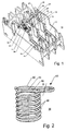
- the Fig. 1 shows the lower housing part 10 of an electrical switching device, here a motor protection switch, which is bounded by two parallel outer walls 11 and 12 and intermediate walls 13 and 14, are formed by the chambers 15, 16 and 17, in which there are electromagnetic triggers and other components, wherein the structure of the electromagnetic release based on the Figures 2 . 3 and 4 will be described in more detail.
- the electromagnetic actuator has a yoke 50 which has a U-shaped portion 51 having a first leg 52 and a second leg 53; at the free end of the second leg 53, a bent perpendicular to this bend 54 is formed on which a retaining leg 55 is formed on which a not shown in the drawing thermal release is attached.
- a coil 56 is used, which coil 56 has a bobbin 57 with two radial flanges 58 and 59; around the bobbin is one in the Fig. 4 not shown coil wound.
- an armature 80 having two sections 81 and 60 of different diameters; the first larger diameter portion 81 is completely within the bobbin, whereas the second portion 60 protrudes with a smaller diameter from the bobbin 57 and thereby projects beyond the first leg 52.
- the flange 59 is formed widened, in particular, the axial thickness of the flange 59 is increased relative to the axial thickness of the flange 58.
- an inwardly projecting bar 61 is provided, which partially surrounds the second portion 60 of the armature.
- an arm 62 is formed, which projects in the longitudinal direction of the armature 80 and at its free end a nose 63 which nose 63 protrudes toward the flange 59 and with a restraining spring 38, see Fig. 2 , cooperates.
- the shackle spring 38 comprises a plurality of circular, helically associated windings 39, the last turn 40 is oval shaped and has two legs 41 and 42 which are perpendicular to the spring axis and span a plane which is also perpendicular to the axis.
- the winding 40 with the two legs 41 and 42 forms a projection 43, which projects radially beyond the envelope of the coil spring 38 and the restraint spring 38. With this portion, which projects beyond the envelope of the restraining spring 38, the restraining spring cooperates with the nose 63 by the nose 63 engages in the space between the legs 41 and 42.
- the armature 80 has at the free end of the second portion 60 of smaller diameter, a mushroom 65 which is disposed from the free end portion of the second portion 60 at a distance D1 and therebetween a mushroom foot 66, with which the fungus 65 with the second section 60 is connected.
- the outer diameter of the mushroom foot 66 is sized to be encompassed by the two legs 41, 42 so that these two legs engage between the second portion 60 and the mushroom 65, thus coupling the fetlock spring to the armature 80.
- the first leg 52 has an opening 82 which is formed as an open slot, so that the bobbin, together with the coil and the armature parallel to the longitudinal extent of the leg 52 toward the web 67, which connects the two legs 52 and 53 together can be seen by the tines 68 and 69 in existing in the flange 59 pockets 70, 71, see Fig. 6 , can be inserted.
- the Fig. 6 also shows the arm 62 with the nose 63, which is arranged projecting on an L-leg 72 of the arm to the flange 59 out. The nose 63 attacks, as in Fig. 4 can be seen in the space between the windings 40 and 41 a.
- the advantage of the stepped armature is that the larger diameter portion that runs inside the coil receives a larger magnetic force; By using a larger amount of iron, saturation occurs later so that stronger and earlier attraction occurs at equal currents, as compared to an anchor having a non-stepped outer diameter.
- the armature 80 is first inserted into the bobbin 57, wherein previously, of course, the coil is wound around the bobbin 57. Then, the bobbin 57 is inserted with the anchor used in the yoke or in the slot 82 by the tines 68 and 69 engage in the pockets 70 and 71 sized for it; In this case, the protruding from the bobbin anchor part, that is, therefore, the second portion 60 of smaller diameter is inserted through the opening of the elongated hole in the same; Thereafter, the restraint spring 38 is attached to the bobbin 57, and the flange 59 projecting portion 60, wherein the two windings 40, 41 engaged in the region of the mushroom foot 66 and the projection of the windings 40, 41 are placed behind the nose 63.
- the bar 61 on the spool flange limits the movement of the armature 80 toward the first leg 52.
- the strip 61 overlaps only a portion of the inner diameter, so that only this small portion with the gradation 61 1 is used to guide the restraint spring 38.
- the Fig. 3 shows a slot 83 in the leg 55, in this slot 80, the foot of a bimetallic strip, which is perpendicular to the leg 55, used and fixed therein.
Landscapes
- Physics & Mathematics (AREA)
- Electromagnetism (AREA)
- Electromagnets (AREA)
- Breakers (AREA)
Abstract
Description
- Die Erfindung betrifft ein Schaltgerät, insbesondere einen Motorschutzschalter, mit einem Magnetauslöser mit einem Joch, welches einen U-förmigen ersten Abschnitt mit einem ersten Schenkel und einem parallel dazu verlaufenden Schenkel aufweist, zwischen denen eine Spule mit einer Spulenwicklung, einem Anker und einem Spulenkörper angeordnet sind, wobei der Anker eine Öffnung durchgreift, und mit einer Fesselfeder, die am freien Ende des Ankers außerhalb des ersten Schenkels angeschlossen ist, gemäß dem Oberbegriff des Anspruches 1. Die Erfindung betrifft weiterhin ein Verfahren zur Montage des Magnetauslösers des Motorschutzschalters nach Anspruch 4.
- Ein derartiges Schaltgerät ist aus der
DE 199 35 662 A1 bekannt geworden. - Der Magnetauslöser für das elektrische Schaltgerät besitzt ein Joch, welches einen U-förmigen ersten Abschnitt mit einem ersten und einem zweiten Schenkel aufweist, zwischen denen eine Spule mit Spulenwicklung, Anker und Spulenkörper angeordnet sind. Der Anker durchgreift dabei eine Öffnung in dem ersten Schenkel der U-Form und ist mit einer Fesselfeder, die am freien Ende des Ankers außerhalb des ersten Schenkels angeschlossen ist, gefesselt.
- Über die Montage des Ankers zusammen mit dem Spulenkörper ist in der
DE 199 35 662 A1 nichts ausgesagt. - Aufgabe der Erfindung ist es, den Motorschalter und insbesondere den Magnetauslöser der eingangs genannten Art so auszugestalten, dass eine einfache Montage des Ankers mit Spule und Spulenkörper möglich ist. Weiterhin soll ein einfaches Montageverfahren angegeben werden.
- Diese Aufgabe wird erfindungsgemäß durch die Merkmale des Anspruches 1 gelöst.
- Erfindungsgemäß ist die Öffnung als ein zum freien Ende des ersten Schenkels offenes Langloch ausgebildet, so dass die Spule mit dem Spulenkörper in Richtung der Längserstreckung des ersten Schenkels zu dem die beiden Schenkel miteinander verbindenden Steg der U-Form hin in das Langloch einführbar beziehungsweise eingeführt ist, wobei der Anker das Langloch durchgreift.
- Insbesondere mit der Ausgestaltung der Öffnung als Langloch wird die Montage erheblich vereinfacht, weil Einfädelungsarbeiten des Ankers in eine geschlossene Öffnung nicht mehr ausgeführt werden müssen.
- In einer besonders vorteilhaften Ausführungsform der Erfindung wird diese Vereinfachung weiterhin dadurch unterstützt, dass der Spulenkörper zwei radiale Flansche aufweist, von denen der erste Flansch an der Innenfläche des zweiten Schenkels anliegt und dass im zweiten Flansch Taschen vorgesehen sind, in welche die das Langloch begrenzenden Zinken eingreifen.
- Gemäß einer weiteren Ausgestaltung der Erfindung kann der Durchmesser des Ankers gestuft sein mit einem Bereich größeren Durchmessers, der sich im Spulenkörper befindet, und mit einem Bereich kleineren Durchmessers, der aus dem ersten Schenkel herausragt und an dessen Ende die Fesselfeder angreift.
- Dadurch kann eine Erhöhung der Auslösekraft erreicht werden, weil sich im Inneren der Spule der Bereich mit dem größeren Durchmesser befindet.
- Das Verfahren zur Montage des Magnetauslösers, mit dem die Montage durchgeführt werden kann, ist dadurch gekennzeichnet, dass zunächst der Spulenkörper mit einer Spule bewickelt, sodann der Anker ins Innere des Spulenkörpers eingeführt wird, dass danach der Spulenkörper zusammen mit dem Anker und der Spule auf den ersten Schenkel des Joches aufgeschoben wird und dass danach die Fesselfeder über den Anker geschoben und fixiert wird.
- Weitere vorteilhafte Ausgestaltungen und Verbesserungen der Erfindung sind den weiteren Unteransprüchen zu entnehmen.
- Anhand der Zeichnung, in der ein Ausführungsbeispiel der Erfindung dargestellt ist, sollen die Erfindung sowie weitere vorteilhafte Ausgestaltungen und Verbesserung der Erfindung und weitere Vorteile näher erläutert und beschrieben werden.
- Es zeigen:
- Fig. 1
- eine Einsicht in das Gehäuseunterteil eines Motorschutzschalters,
- Fig. 2
- eine perspektivische Ansicht einer Fesselfeder,
- Fig. 3
- eine perspektivische Ansicht eines Joches,
- Fig. 4
- eine Schnittansicht des Joches mit Spule, Spulenkörper, Anker und Fesselfeder,
- Fig. 5
- eine Seitenansicht eines Ankers für den Magnetauslöser und
- Fig. 6
- eine perspektivische Ansicht des Spulenkörpers für den Magnetauslöser.
- Die
Fig. 1 zeigt das Gehäuseunterteil 10 eines elektrischen Schaltgerätes, hier eines Motorschutzschalters, das von zwei parallelen Außenwänden 11 und 12 begrenzt ist und Zwischenwände 13 und 14 besitzt, durch die Kammern 15, 16 und 17 gebildet sind, in denen sich elektromagnetische Auslöser und weitere Komponenten befinden, wobei der Aufbau des elektromagnetischen Auslösers anhand derFiguren 2 ,3 und 4 näher beschrieben werden soll. - In den beiden Seitenwänden 11 und 12 ist je eine Lagerstelle 18, 19 für eine Schwenkwelle 20 angeordnet, an welcher Schwenkwelle 20 Arme 21, 22 und 23 angeformt sind, mit der in nicht näher dargestellter Weise eine Verklinkungsstelle in einem Schaltschloss geöffnet werden kann.
- Diese Anordnung ist, wie aus der
DE 199 35 662 A1 ersichtlich ist, Stand der Technik. - In der
Fig. 1 ist ein elektromagnetischer Auslöser eingesetzt; selbstverständlich sind auch in den Kammern 14 und 16 elektromagnetische Auslöser eingebaut. Die weiteren Komponenten, wie Anschlussklemmen, bewegliche Kontaktstücke mit Kontaktbrücken und dergleichen, sind nicht dargestellt. - Es sei nun Bezug genommen auf die
Fig. 4 . - Der elektromagnetische Auslöser besitzt ein Joch 50, welches einen U-förmigen Abschnitt 51 aufweist, der einen ersten Schenkel 52 und einen zweiten Schenkel 53 aufweist; am freien Ende des zweiten Schenkels 53 ist eine senkrecht dazu abgebogene Abwinklung 54 angeformt, an der ein Halteschenkel 55 angeformt ist, an dem ein in der Zeichnung nicht dargestellter thermischer Auslöser befestigt ist.
- Zwischen den ersten und dem zweiten Schenkel 52, 53 ist eine Spule 56 eingesetzt, welche Spule 56 einen Spulenkörper 57 mit zwei Radialflanschen 58 und 59 aufweist; um den Spulenkörper herum ist eine in der
Fig. 4 nicht dargestellte Spule gewickelt. - Innerhalb des Spulenkörpers 57 befindet sich ein Anker 80, der zwei Abschnitte 81 und 60 mit unterschiedlichem Durchmesser aufweist; der erste Abschnitt 81 mit größerem Durchmesser befindet sich vollständig innerhalb des Spulenkörpers, wogegen der zweite Abschnitt 60 mit geringerem Durchmesser aus dem Spulenkörper 57 herausragt und dabei auch den ersten Schenkel 52 überragt. Der Flansch 59 ist verbreitert ausgebildet, wobei insbesondere die axiale Dicke des Flansches 59 gegenüber der axialen Dicke des Flansches 58 vergrößert ist. Im Bereich des Flansches 59, an dessen Innenseite, ist eine nach innen vorspringende Leiste 61 vorgesehen, die den zweiten Abschnitt 60 des Ankers teilweise umgreift. Auf der Außenseite des Flansches 59 ist ein Arm 62 angeformt, der in Längsrichtung des Ankers 80 vorspringt und an seinem freien Ende eine Nase 63 aufweist, welche Nase 63 in Richtung zum Flansch 59 vorspringt und mit einer Fesselfeder 38, siehe
Fig. 2 , zusammenwirkt. - Die Fesselfeder 38 umfasst mehrere kreisförmige, schraubenförmig einander zugeordnete Windungen 39, deren letzte Windung 40 oval verformt ist und zwei Schenkel 41 und 42 aufweist, die senkrecht zur Federachse verlaufen und eine Ebene aufspannen, die ebenfalls senkrecht zu der Achse verläuft. Die Windung 40 mit den beiden Schenkeln 41 und 42 bildet einen Vorsprung 43, der radial die Umhüllende der Schraubenfeder 38 beziehungsweise der Fesselfeder 38 überragt. Mit diesem Teilbereich, der die Umhüllende der Fesselfeder 38 überragt, wirkt die Fesselfeder mit der Nase 63 zusammen, indem die Nase 63 in den Zwischenraum zwischen den Schenkeln 41 und 42 eingreift.
- Wie aus der
Fig. 5 zu entnehmen ist, besitzt der Anker 80 am freien Ende des zweiten Abschnitts 60 mit geringerem Durchmesser einen Pilz 65, der von dem freien Endbereich des zweiten Abschnittes 60 in einem Abstand D1 angeordnet ist und dazwischen einen Pilzfuß 66 aufweist, mit dem der Pilz 65 mit dem zweiten Abschnitt 60 verbunden ist. Der Außendurchmesser des Pilzfußes 66 ist so bemessen, dass er von den beiden Schenkeln 41, 42 umfasst werden kann, so dass diese beiden Schenkel zwischen den zweiten Abschnitt 60 und den Pilz 65 greifen und auf diese Weise die Fesselfeder mit dem Anker 80 gekoppelt ist. - Es sei nun Bezug genommen auf die
Fig. 3 , in der lediglich das Joch 50 ohne zusätzliche Elemente gezeichnet ist. - Der erste Schenkel 52 besitzt eine Öffnung 82, die als offenes Langloch ausgebildet ist, so dass der Spulenkörper zusammen mit der Spule und dem Anker parallel zu der Längserstreckung des Schenkels 52 hin zum Steg 67, der die beiden Schenkel 52 und 53 miteinander verbindet, eingeschoben werden kann, indem die Zinken 68 und 69 in im Flansch 59 vorhandene Taschen 70, 71, siehe
Fig. 6 , eingeschoben werden kann. DieFig. 6 zeigt auch den Arm 62 mit der Nase 63, die an einem L-Schenkel 72 des Armes zum Flansch 59 hin vorspringend angeordnet ist. Die Nase 63 greift, wie inFig. 4 ersichtlich, in den Zwischenraum zwischen den Windungen 40 und 41 ein. - Hierdurch wird die Montage des Spulenkörpers erheblich vereinfacht.
- Der Vorteil des gestuften Ankers besteht darin, dass der Bereich größeren Durchmessers, der innerhalb der Spule verläuft, eine größere Magnetkraft erhält; dadurch, dass eine größere Menge an Eisen verwendet wird, tritt eine Sättigung später ein, so dass eine stärkere und frühere Anziehung bei gleichen Strömen erfolgt, im Vergleich zu einem Anker, der einen nicht gestuften Außendurchmesser aufweist.
- Zur Montage wird zunächst der Anker 80 in den Spulenkörper 57 eingeschoben, wobei vorher natürlich die Spule um den Spulenkörper 57 herumgewickelt ist. Sodann wird der Spulenkörper 57 mit dem eingesetzten Anker in das Joch beziehungsweise in das Langloch 82 eingeschoben, indem die Zinken 68 und 69 in die dafür bemessenen Taschen 70 und 71 eingreifen; dabei wird der aus dem Spulenköper überstehende Ankerteil, das heißt also der zweite Abschnitt 60 mit geringerem Durchmesser durch die Öffnung des Langloches in dasselbe eingeführt; danach wird die Fesselfeder 38 auf den den Spulenkörper 57, beziehungsweise den Flansch 59 überstehenden Abschnitt 60 aufgesteckt, wobei die beiden Windungen 40, 41 in den Bereich des Pilzfußes 66 eingerastet und der Vorsprung der Windungen 40, 41 hinter die Nase 63 gelegt werden.
- Die Leiste 61 am Spulenflansch begrenzt die Bewegung des Ankers 80 hin zum ersten Schenkel 52.
- Wie aus der
Fig. 6 ersichtlich ist, übergreift die Leiste 61 lediglich einen Teilbereich des Innendurchmessers, so dass nur dieser kleine Teilbereich mit der Stufung 611 zur Führung der Fesselfeder 38 dient. - Die
Fig. 3 zeigt ein Langloch 83 im Schenkel 55, in dieses Langloch 80 wird der Fuß eines Thermobimetalls, welches senkrecht zum Schenkel 55 verläuft, eingesetzt und darin fixiert. -
- 10
- Gehäuseunterteil
- 11
- Außenwand
- 12
- Außenwand
- 13
- Zwischenwand
- 14
- Zwischenwand
- 15
- Kammer
- 16
- Kammer
- 17
- Kammer
- 18
- Lagerstelle
- 19
- Lagerstelle
- 20
- Schwenkwelle
- 21
- Arm
- 22
- Arm
- 23
- Arm
- 38
- Fesselfeder
- 39
- Windung
- 40
- letzte Windung
- 41
- Windungsschenkel
- 42
- Windungsschenkel
- 43
- Vorsprung
- 50
- Joch
- 51
- U-förmiger Joch-Abschnitt
- 52
- erster Schenkel
- 53
- zweiter Schenkel
- 54
- senkrechte Abwinklung
- 55
- Halteschenkel
- 56
- Spule
- 57
- Spulenkörper
- 58
- Radialflansch des Spulenkörpers
- 59
- Radialflansch des Spulenkörpers
- 60
- zweiter Anker-Abschnitt
- 61
- Leiste
- 62
- Arm
- 63
- Nase
- 65
- Pilz
- 66
- Pilzfuß
- 67
- Steg
- 68
- Zinken
- 69
- Zinken
- 70
- Tasche im Flansch
- 71
- Tasche im Flansch
- 72
- L-Schenkel
- 80
- Anker
- 81
- erster Anker-Abschnitt
- 82
- Öffnung im ersten Schenkel
- 83
- Langloch
Claims (4)
- Schaltgerät, insbesondere Motorschutzschalter, mit einem Magnetauslöser mit einem Joch (50), welches einen U-förmigen ersten Abschnitt (51) mit einem ersten Schenkel (52) und einem parallel dazu verlaufenden Schenkel (53) aufweist, zwischen denen eine Spule mit einer Spulenwichlung, einem Anker (80) und einem Spulenkörper (57) angeordnet sind, wobei der Anker (80) eine Öffnung (62) durchgreift, und mit einer Fesselfeder (38), die am freien Ende des Ankers (80) außerhalb des ersten Schenkels (52) angeschlossen ist, dadurch gekennzeichnet, dass die Öffnung (82) als ein zum freien Ende des ersten Schenkels (52) offenes Langloch (82) ausgebildet ist, so dass die Spule mit dem Spulenkörper (57) in Richtung der Längserstreckung des ersten Schenkels (52) zu dem die beiden Schenkel (52, 53) miteinander verbindenden Steg (67) der U-Form hin in das Langloch (82) einführbar beziehungsweise eingeführt ist, wobei der Anker das Langloch durchgreift.
- Schaltgerät nach Anspruch 1, dadurch gekennzeichnet, dass der Spulenkörper (57) zwei radiale Flansche (58, 59) aufweist, von denen der erste Flansch (58) an der Innenfläche des zweiten Schenkels (53) anliegt und dass im zweiten Flansch (59) Taschen (70, 71) vorgesehen sind, in welche die das Langloch (82) begrenzenden Zinken (68, 69) eingreifen.
- Schaltgerät nach einem der vorherigen Ansprüche, dadurch gekennzeichnet, dass der Durchmesser des Ankers (80) gestuft ist und einen Bereich (81) mit größerem Durchmesser, der sich vollständig im Spulenkörper (57) befindet, und einem Bereich (60) kleineren Durchmessers aufweist, der aus dem ersten Schenkel (52) herausragt und an dessen Ende die Fesselfeder (38) angreift.
- Verfahren zur Montage des Magnetauslösers gemäß einem der Ansprüche 1 bis 3, dadurch gekennzeichnet, dass zunächst der Spulenkörper mit einer Spule bewickelt, sodann der Anker ins Innere des Spulenkörpers eingeführt wird, dass danach der Spulenkörper zusammen mit dem Anker und der Spule auf den ersten Schenkel des Joches aufgeschoben wird und dass danach die Fesselfeder über den Anker geschoben und fixiert wird.
Applications Claiming Priority (1)
| Application Number | Priority Date | Filing Date | Title |
|---|---|---|---|
| DE102008012149A DE102008012149A1 (de) | 2008-03-01 | 2008-03-01 | Schaltgerät |
Publications (2)
| Publication Number | Publication Date |
|---|---|
| EP2096656A1 true EP2096656A1 (de) | 2009-09-02 |
| EP2096656B1 EP2096656B1 (de) | 2015-04-08 |
Family
ID=40756269
Family Applications (1)
| Application Number | Title | Priority Date | Filing Date |
|---|---|---|---|
| EP09001281.6A Active EP2096656B1 (de) | 2008-03-01 | 2009-01-30 | Schaltgerät |
Country Status (4)
| Country | Link |
|---|---|
| US (1) | US8049584B2 (de) |
| EP (1) | EP2096656B1 (de) |
| CN (1) | CN101556883B (de) |
| DE (1) | DE102008012149A1 (de) |
Families Citing this family (4)
| Publication number | Priority date | Publication date | Assignee | Title |
|---|---|---|---|---|
| DE102010005345B4 (de) | 2010-01-21 | 2022-04-21 | Abb Schweiz Ag | Elektrisches Schaltgerät in modularer Bauweise |
| GB2498806A (en) * | 2012-01-30 | 2013-07-31 | P S Electrical Services 1998 Ltd | Air circuit breaker coil adapter |
| DE102013114663A1 (de) | 2013-12-20 | 2015-06-25 | Eaton Industries Austria Gmbh | Schaltgerät |
| CN111640601A (zh) * | 2020-06-09 | 2020-09-08 | 广州坤开机电设备有限公司 | 一种拼接式可插拔的小型断路器及其使用方法 |
Citations (4)
| Publication number | Priority date | Publication date | Assignee | Title |
|---|---|---|---|---|
| EP0569652A1 (de) * | 1992-05-13 | 1993-11-18 | Hager Electro S.A. | Magnetauslöser für Schutzschalter, entsprechende Baugruppe und diese enthaltende Schutzschalter |
| DE19845476A1 (de) * | 1998-10-02 | 2000-04-13 | Aeg Niederspannungstech Gmbh | Magnetsystem |
| DE19935662A1 (de) | 1999-07-29 | 2001-02-01 | Abb Patent Gmbh | Elektromagnetischer Auslöser |
| DE102005020167A1 (de) * | 2005-04-30 | 2006-11-09 | Abb Patent Gmbh | Elektromagnetischer Auslöser für ein elektrisches Installationsgerät |
Family Cites Families (15)
| Publication number | Priority date | Publication date | Assignee | Title |
|---|---|---|---|---|
| US3959755A (en) * | 1974-12-13 | 1976-05-25 | Airpax Electronics Incorporated | Circuit breaker with improved delay |
| US4250477A (en) * | 1978-09-07 | 1981-02-10 | Allen-Bradley Company | Mechanical latch apparatus |
| US4288769A (en) * | 1979-11-28 | 1981-09-08 | General Electric Company | Ambient temperature responsive trip device for static trip circuit breakers |
| DE3339401A1 (de) * | 1983-10-29 | 1985-05-09 | Sursum Elektrizitätsgesellschaft Leyhausen GmbH & Co, 8500 Nürnberg | Selbstschalter zum aufsetzen auf schienen |
| US4697163A (en) * | 1986-03-27 | 1987-09-29 | Westinghouse Electric Corp. | Circuit breaker with impact trip delay |
| US4713639A (en) * | 1987-02-20 | 1987-12-15 | Westinghouse Electric Corp. | Circuit breaker with push-to-trip button and trip bar |
| FR2616584B1 (fr) * | 1987-06-11 | 1989-09-29 | Hager Electro | Ensemble magnetothermique de disjonction pour disjoncteur ou disjoncteur differentiel |
| US4973928A (en) * | 1989-03-31 | 1990-11-27 | Westinghouse Electric Corp. | Extender spring for increased magnetic trip settings |
| FR2673487B1 (fr) * | 1991-02-28 | 1993-10-29 | Telemecanique | Interrupteur de protection incorporant un sous-ensemble magnetothermique de declenchement. |
| FR2753836B1 (fr) | 1996-09-23 | 1998-10-30 | Declencheur electromagnetique pour appareil electrique de protection | |
| US5831501A (en) * | 1997-04-14 | 1998-11-03 | Eaton Corporation | Adjustable trip unit and circuit breaker incorporating same |
| EP1105900B1 (de) * | 1998-08-14 | 2002-10-30 | Siemens Aktiengesellschaft | Einrichtung mit axial positionierbarer spulenwicklung |
| DE10002773B4 (de) * | 2000-01-22 | 2005-12-15 | Abb Patent Gmbh | Motorschutzschalter |
| DE60032137T2 (de) * | 2000-09-12 | 2007-10-11 | Hager-Electro S.A.S. | Schutzschalter mit magnetothermischer Auslöseeinheit |
| US6940373B2 (en) * | 2003-11-21 | 2005-09-06 | Ark-Les Corporation | Fast engage, slow release electrical actuator |
-
2008
- 2008-03-01 DE DE102008012149A patent/DE102008012149A1/de not_active Withdrawn
-
2009
- 2009-01-30 EP EP09001281.6A patent/EP2096656B1/de active Active
- 2009-02-27 CN CN200910118670.2A patent/CN101556883B/zh active Active
- 2009-02-27 US US12/395,064 patent/US8049584B2/en active Active
Patent Citations (4)
| Publication number | Priority date | Publication date | Assignee | Title |
|---|---|---|---|---|
| EP0569652A1 (de) * | 1992-05-13 | 1993-11-18 | Hager Electro S.A. | Magnetauslöser für Schutzschalter, entsprechende Baugruppe und diese enthaltende Schutzschalter |
| DE19845476A1 (de) * | 1998-10-02 | 2000-04-13 | Aeg Niederspannungstech Gmbh | Magnetsystem |
| DE19935662A1 (de) | 1999-07-29 | 2001-02-01 | Abb Patent Gmbh | Elektromagnetischer Auslöser |
| DE102005020167A1 (de) * | 2005-04-30 | 2006-11-09 | Abb Patent Gmbh | Elektromagnetischer Auslöser für ein elektrisches Installationsgerät |
Also Published As
| Publication number | Publication date |
|---|---|
| EP2096656B1 (de) | 2015-04-08 |
| US20090219662A1 (en) | 2009-09-03 |
| CN101556883B (zh) | 2014-08-06 |
| US8049584B2 (en) | 2011-11-01 |
| CN101556883A (zh) | 2009-10-14 |
| DE102008012149A1 (de) | 2009-09-03 |
Similar Documents
| Publication | Publication Date | Title |
|---|---|---|
| DE202005021724U1 (de) | Magnetventil | |
| DE10026813B4 (de) | Elektromagnetischer Auslöser | |
| DE10205350B4 (de) | Elektromagnetisches Relais | |
| EP2096656B1 (de) | Schaltgerät | |
| EP1036399B1 (de) | Magnetsystem | |
| DE102007019684A1 (de) | Magnetsystem für eine elektrische Schaltvorrichtung | |
| DE3310914C2 (de) | ||
| DE60022531T2 (de) | Elektromagnetischer aktuator | |
| WO2018054714A1 (de) | Elektromagnetisches relais | |
| DE102008021768B4 (de) | Elektromagnetischer Auslöser, Verfahren zur Herstellung eines elektromagnetischen Auslösers und Leitungsschutzschalter mit einem elektromagnetischen Auslöser | |
| DE102017110849A1 (de) | Elektromagnet | |
| EP1073083B1 (de) | Elektromagnetischer Auslöser | |
| EP0513010B1 (de) | Elektromagnetisches relais | |
| DE2901552A1 (de) | Schalter mit einem elektromagneten mit verschiebbaren festen elementen | |
| DE102018200084B4 (de) | Verfahren zur Herstellung einer elektromagnetischen Ventilanordnung sowie elektromagnetische Ventilanordnung | |
| DE3319374C2 (de) | ||
| EP1878037A2 (de) | Elektromagnetischer auslöser für ein elektrisches installationsgerät | |
| EP1473751B1 (de) | Elektromagnetischer Auslöser | |
| EP1728309B1 (de) | Flachstator mit fixierung von polschuhen durch statorgehäuse | |
| DE4143063C2 (de) | Minielektromagnet und seine Verwendung als Relais | |
| DE102016107818B4 (de) | Drosselanordnung mit einem Einsatz | |
| DE102016201409A1 (de) | Kamm für ein schmales Relais, Kammanordnung und Relais | |
| EP2042749B1 (de) | Klammer für Planarkerne | |
| DE19602641B4 (de) | Elektromagnetisches Relais mit flachem Anker | |
| DE102024121818A1 (de) | Differenzstromauslöser |
Legal Events
| Date | Code | Title | Description |
|---|---|---|---|
| PUAI | Public reference made under article 153(3) epc to a published international application that has entered the european phase |
Free format text: ORIGINAL CODE: 0009012 |
|
| AK | Designated contracting states |
Kind code of ref document: A1 Designated state(s): AT BE BG CH CY CZ DE DK EE ES FI FR GB GR HR HU IE IS IT LI LT LU LV MC MK MT NL NO PL PT RO SE SI SK TR |
|
| AX | Request for extension of the european patent |
Extension state: AL BA RS |
|
| 17P | Request for examination filed |
Effective date: 20100122 |
|
| AKX | Designation fees paid |
Designated state(s): AT BE BG CH CY CZ DE DK EE ES FI FR GB GR HR HU IE IS IT LI LT LU LV MC MK MT NL NO PL PT RO SE SI SK TR |
|
| GRAP | Despatch of communication of intention to grant a patent |
Free format text: ORIGINAL CODE: EPIDOSNIGR1 |
|
| INTG | Intention to grant announced |
Effective date: 20150105 |
|
| GRAS | Grant fee paid |
Free format text: ORIGINAL CODE: EPIDOSNIGR3 |
|
| GRAA | (expected) grant |
Free format text: ORIGINAL CODE: 0009210 |
|
| AK | Designated contracting states |
Kind code of ref document: B1 Designated state(s): AT BE BG CH CY CZ DE DK EE ES FI FR GB GR HR HU IE IS IT LI LT LU LV MC MK MT NL NO PL PT RO SE SI SK TR |
|
| REG | Reference to a national code |
Ref country code: GB Ref legal event code: FG4D Free format text: NOT ENGLISH |
|
| REG | Reference to a national code |
Ref country code: CH Ref legal event code: EP |
|
| REG | Reference to a national code |
Ref country code: IE Ref legal event code: FG4D Free format text: LANGUAGE OF EP DOCUMENT: GERMAN |
|
| REG | Reference to a national code |
Ref country code: DE Ref legal event code: R096 Ref document number: 502009010860 Country of ref document: DE Effective date: 20150513 |
|
| REG | Reference to a national code |
Ref country code: AT Ref legal event code: REF Ref document number: 721103 Country of ref document: AT Kind code of ref document: T Effective date: 20150515 |
|
| REG | Reference to a national code |
Ref country code: NL Ref legal event code: VDEP Effective date: 20150408 |
|
| REG | Reference to a national code |
Ref country code: LT Ref legal event code: MG4D |
|
| PG25 | Lapsed in a contracting state [announced via postgrant information from national office to epo] |
Ref country code: NL Free format text: LAPSE BECAUSE OF FAILURE TO SUBMIT A TRANSLATION OF THE DESCRIPTION OR TO PAY THE FEE WITHIN THE PRESCRIBED TIME-LIMIT Effective date: 20150408 |
|
| PG25 | Lapsed in a contracting state [announced via postgrant information from national office to epo] |
Ref country code: PT Free format text: LAPSE BECAUSE OF FAILURE TO SUBMIT A TRANSLATION OF THE DESCRIPTION OR TO PAY THE FEE WITHIN THE PRESCRIBED TIME-LIMIT Effective date: 20150810 Ref country code: ES Free format text: LAPSE BECAUSE OF FAILURE TO SUBMIT A TRANSLATION OF THE DESCRIPTION OR TO PAY THE FEE WITHIN THE PRESCRIBED TIME-LIMIT Effective date: 20150408 Ref country code: FI Free format text: LAPSE BECAUSE OF FAILURE TO SUBMIT A TRANSLATION OF THE DESCRIPTION OR TO PAY THE FEE WITHIN THE PRESCRIBED TIME-LIMIT Effective date: 20150408 Ref country code: LT Free format text: LAPSE BECAUSE OF FAILURE TO SUBMIT A TRANSLATION OF THE DESCRIPTION OR TO PAY THE FEE WITHIN THE PRESCRIBED TIME-LIMIT Effective date: 20150408 Ref country code: NO Free format text: LAPSE BECAUSE OF FAILURE TO SUBMIT A TRANSLATION OF THE DESCRIPTION OR TO PAY THE FEE WITHIN THE PRESCRIBED TIME-LIMIT Effective date: 20150708 Ref country code: HR Free format text: LAPSE BECAUSE OF FAILURE TO SUBMIT A TRANSLATION OF THE DESCRIPTION OR TO PAY THE FEE WITHIN THE PRESCRIBED TIME-LIMIT Effective date: 20150408 |
|
| PG25 | Lapsed in a contracting state [announced via postgrant information from national office to epo] |
Ref country code: IS Free format text: LAPSE BECAUSE OF FAILURE TO SUBMIT A TRANSLATION OF THE DESCRIPTION OR TO PAY THE FEE WITHIN THE PRESCRIBED TIME-LIMIT Effective date: 20150808 Ref country code: LV Free format text: LAPSE BECAUSE OF FAILURE TO SUBMIT A TRANSLATION OF THE DESCRIPTION OR TO PAY THE FEE WITHIN THE PRESCRIBED TIME-LIMIT Effective date: 20150408 Ref country code: GR Free format text: LAPSE BECAUSE OF FAILURE TO SUBMIT A TRANSLATION OF THE DESCRIPTION OR TO PAY THE FEE WITHIN THE PRESCRIBED TIME-LIMIT Effective date: 20150709 |
|
| REG | Reference to a national code |
Ref country code: DE Ref legal event code: R097 Ref document number: 502009010860 Country of ref document: DE |
|
| REG | Reference to a national code |
Ref country code: FR Ref legal event code: PLFP Year of fee payment: 8 |
|
| PG25 | Lapsed in a contracting state [announced via postgrant information from national office to epo] |
Ref country code: DK Free format text: LAPSE BECAUSE OF FAILURE TO SUBMIT A TRANSLATION OF THE DESCRIPTION OR TO PAY THE FEE WITHIN THE PRESCRIBED TIME-LIMIT Effective date: 20150408 Ref country code: EE Free format text: LAPSE BECAUSE OF FAILURE TO SUBMIT A TRANSLATION OF THE DESCRIPTION OR TO PAY THE FEE WITHIN THE PRESCRIBED TIME-LIMIT Effective date: 20150408 |
|
| PLBE | No opposition filed within time limit |
Free format text: ORIGINAL CODE: 0009261 |
|
| STAA | Information on the status of an ep patent application or granted ep patent |
Free format text: STATUS: NO OPPOSITION FILED WITHIN TIME LIMIT |
|
| PG25 | Lapsed in a contracting state [announced via postgrant information from national office to epo] |
Ref country code: SK Free format text: LAPSE BECAUSE OF FAILURE TO SUBMIT A TRANSLATION OF THE DESCRIPTION OR TO PAY THE FEE WITHIN THE PRESCRIBED TIME-LIMIT Effective date: 20150408 Ref country code: RO Free format text: LAPSE BECAUSE OF NON-PAYMENT OF DUE FEES Effective date: 20150408 Ref country code: PL Free format text: LAPSE BECAUSE OF FAILURE TO SUBMIT A TRANSLATION OF THE DESCRIPTION OR TO PAY THE FEE WITHIN THE PRESCRIBED TIME-LIMIT Effective date: 20150408 Ref country code: CZ Free format text: LAPSE BECAUSE OF FAILURE TO SUBMIT A TRANSLATION OF THE DESCRIPTION OR TO PAY THE FEE WITHIN THE PRESCRIBED TIME-LIMIT Effective date: 20150408 |
|
| 26N | No opposition filed |
Effective date: 20160111 |
|
| PG25 | Lapsed in a contracting state [announced via postgrant information from national office to epo] |
Ref country code: BE Free format text: LAPSE BECAUSE OF NON-PAYMENT OF DUE FEES Effective date: 20160131 Ref country code: SI Free format text: LAPSE BECAUSE OF FAILURE TO SUBMIT A TRANSLATION OF THE DESCRIPTION OR TO PAY THE FEE WITHIN THE PRESCRIBED TIME-LIMIT Effective date: 20150408 |
|
| PG25 | Lapsed in a contracting state [announced via postgrant information from national office to epo] |
Ref country code: LU Free format text: LAPSE BECAUSE OF FAILURE TO SUBMIT A TRANSLATION OF THE DESCRIPTION OR TO PAY THE FEE WITHIN THE PRESCRIBED TIME-LIMIT Effective date: 20160130 |
|
| REG | Reference to a national code |
Ref country code: CH Ref legal event code: PL |
|
| GBPC | Gb: european patent ceased through non-payment of renewal fee |
Effective date: 20160130 |
|
| PG25 | Lapsed in a contracting state [announced via postgrant information from national office to epo] |
Ref country code: MC Free format text: LAPSE BECAUSE OF FAILURE TO SUBMIT A TRANSLATION OF THE DESCRIPTION OR TO PAY THE FEE WITHIN THE PRESCRIBED TIME-LIMIT Effective date: 20150408 |
|
| PG25 | Lapsed in a contracting state [announced via postgrant information from national office to epo] |
Ref country code: GB Free format text: LAPSE BECAUSE OF NON-PAYMENT OF DUE FEES Effective date: 20160130 Ref country code: CH Free format text: LAPSE BECAUSE OF NON-PAYMENT OF DUE FEES Effective date: 20160131 Ref country code: LI Free format text: LAPSE BECAUSE OF NON-PAYMENT OF DUE FEES Effective date: 20160131 |
|
| REG | Reference to a national code |
Ref country code: IE Ref legal event code: MM4A |
|
| REG | Reference to a national code |
Ref country code: FR Ref legal event code: PLFP Year of fee payment: 9 |
|
| PG25 | Lapsed in a contracting state [announced via postgrant information from national office to epo] |
Ref country code: IE Free format text: LAPSE BECAUSE OF NON-PAYMENT OF DUE FEES Effective date: 20160130 |
|
| REG | Reference to a national code |
Ref country code: AT Ref legal event code: MM01 Ref document number: 721103 Country of ref document: AT Kind code of ref document: T Effective date: 20160130 |
|
| PGFP | Annual fee paid to national office [announced via postgrant information from national office to epo] |
Ref country code: FR Payment date: 20170120 Year of fee payment: 9 |
|
| PG25 | Lapsed in a contracting state [announced via postgrant information from national office to epo] |
Ref country code: AT Free format text: LAPSE BECAUSE OF NON-PAYMENT OF DUE FEES Effective date: 20160130 |
|
| PG25 | Lapsed in a contracting state [announced via postgrant information from national office to epo] |
Ref country code: SE Free format text: LAPSE BECAUSE OF FAILURE TO SUBMIT A TRANSLATION OF THE DESCRIPTION OR TO PAY THE FEE WITHIN THE PRESCRIBED TIME-LIMIT Effective date: 20150408 |
|
| PGFP | Annual fee paid to national office [announced via postgrant information from national office to epo] |
Ref country code: IT Payment date: 20170124 Year of fee payment: 9 |
|
| PG25 | Lapsed in a contracting state [announced via postgrant information from national office to epo] |
Ref country code: MT Free format text: LAPSE BECAUSE OF FAILURE TO SUBMIT A TRANSLATION OF THE DESCRIPTION OR TO PAY THE FEE WITHIN THE PRESCRIBED TIME-LIMIT Effective date: 20150408 |
|
| PG25 | Lapsed in a contracting state [announced via postgrant information from national office to epo] |
Ref country code: HU Free format text: LAPSE BECAUSE OF FAILURE TO SUBMIT A TRANSLATION OF THE DESCRIPTION OR TO PAY THE FEE WITHIN THE PRESCRIBED TIME-LIMIT; INVALID AB INITIO Effective date: 20090130 Ref country code: CY Free format text: LAPSE BECAUSE OF FAILURE TO SUBMIT A TRANSLATION OF THE DESCRIPTION OR TO PAY THE FEE WITHIN THE PRESCRIBED TIME-LIMIT Effective date: 20150408 |
|
| PG25 | Lapsed in a contracting state [announced via postgrant information from national office to epo] |
Ref country code: TR Free format text: LAPSE BECAUSE OF FAILURE TO SUBMIT A TRANSLATION OF THE DESCRIPTION OR TO PAY THE FEE WITHIN THE PRESCRIBED TIME-LIMIT Effective date: 20150408 Ref country code: MK Free format text: LAPSE BECAUSE OF FAILURE TO SUBMIT A TRANSLATION OF THE DESCRIPTION OR TO PAY THE FEE WITHIN THE PRESCRIBED TIME-LIMIT Effective date: 20150408 |
|
| PG25 | Lapsed in a contracting state [announced via postgrant information from national office to epo] |
Ref country code: BG Free format text: LAPSE BECAUSE OF FAILURE TO SUBMIT A TRANSLATION OF THE DESCRIPTION OR TO PAY THE FEE WITHIN THE PRESCRIBED TIME-LIMIT Effective date: 20150408 |
|
| PG25 | Lapsed in a contracting state [announced via postgrant information from national office to epo] |
Ref country code: FR Free format text: LAPSE BECAUSE OF NON-PAYMENT OF DUE FEES Effective date: 20180131 |
|
| REG | Reference to a national code |
Ref country code: FR Ref legal event code: ST Effective date: 20180928 |
|
| PG25 | Lapsed in a contracting state [announced via postgrant information from national office to epo] |
Ref country code: IT Free format text: LAPSE BECAUSE OF NON-PAYMENT OF DUE FEES Effective date: 20180130 |
|
| REG | Reference to a national code |
Ref country code: DE Ref legal event code: R081 Ref document number: 502009010860 Country of ref document: DE Owner name: ABB SCHWEIZ AG, CH Free format text: FORMER OWNER: ABB AG, 68165 MANNHEIM, DE |
|
| PGFP | Annual fee paid to national office [announced via postgrant information from national office to epo] |
Ref country code: DE Payment date: 20260121 Year of fee payment: 18 |