EP2096660A2 - Magnetron - Google Patents
Magnetron Download PDFInfo
- Publication number
- EP2096660A2 EP2096660A2 EP09152226A EP09152226A EP2096660A2 EP 2096660 A2 EP2096660 A2 EP 2096660A2 EP 09152226 A EP09152226 A EP 09152226A EP 09152226 A EP09152226 A EP 09152226A EP 2096660 A2 EP2096660 A2 EP 2096660A2
- Authority
- EP
- European Patent Office
- Prior art keywords
- magnet ring
- anode cylinder
- magnet
- ring
- magnetron
- Prior art date
- Legal status (The legal status is an assumption and is not a legal conclusion. Google has not performed a legal analysis and makes no representation as to the accuracy of the status listed.)
- Withdrawn
Links
- 230000004907 flux Effects 0.000 abstract description 44
- 238000010586 diagram Methods 0.000 description 29
- 230000006641 stabilisation Effects 0.000 description 10
- 238000011105 stabilization Methods 0.000 description 10
- 238000001816 cooling Methods 0.000 description 6
- 230000010355 oscillation Effects 0.000 description 5
- XEEYBQQBJWHFJM-UHFFFAOYSA-N Iron Chemical compound [Fe] XEEYBQQBJWHFJM-UHFFFAOYSA-N 0.000 description 4
- 239000000696 magnetic material Substances 0.000 description 3
- 229910052742 iron Inorganic materials 0.000 description 2
- 238000000034 method Methods 0.000 description 2
- 238000006243 chemical reaction Methods 0.000 description 1
- 238000004519 manufacturing process Methods 0.000 description 1
Images


Classifications
-
- H—ELECTRICITY
- H01—ELECTRIC ELEMENTS
- H01J—ELECTRIC DISCHARGE TUBES OR DISCHARGE LAMPS
- H01J25/00—Transit-time tubes, e.g. klystrons, travelling-wave tubes, magnetrons
- H01J25/50—Magnetrons, i.e. tubes with a magnet system producing an H-field crossing the E-field
- H01J25/52—Magnetrons, i.e. tubes with a magnet system producing an H-field crossing the E-field with an electron space having a shape that does not prevent any electron from moving completely around the cathode or guide electrode
- H01J25/58—Magnetrons, i.e. tubes with a magnet system producing an H-field crossing the E-field with an electron space having a shape that does not prevent any electron from moving completely around the cathode or guide electrode having a number of resonators; having a composite resonator, e.g. a helix
- H01J25/587—Multi-cavity magnetrons
-
- H—ELECTRICITY
- H01—ELECTRIC ELEMENTS
- H01J—ELECTRIC DISCHARGE TUBES OR DISCHARGE LAMPS
- H01J23/00—Details of transit-time tubes of the types covered by group H01J25/00
- H01J23/02—Electrodes; Magnetic control means; Screens
- H01J23/10—Magnet systems for directing or deflecting the discharge along a desired path, e.g. a spiral path
Definitions
- the present invention relates to a magnetron used for a device utilizing a microwave such as a microwave oven.
- the aforesaid magnetron is configured in a manner, as an example, that a magnet ring (also called as a conversion plate or a shim plate) formed by magnetic material is disposed between an anode cylinder having anode vanes disposed radially on the inner wall surface thereof and an circular magnet disposed on the opening end side of the anode cylinder, in order to improve a magnetic force in an active space at the periphery of a cathode structure (refer JP-A-2002-163993 , for example). Since the magnet ring is disposed, much magnetic flux can be conducted into the active space, so that the efficiency of a magnetic circuit can be improved.
- a magnet ring also called as a conversion plate or a shim plate formed by magnetic material is disposed between an anode cylinder having anode vanes disposed radially on the inner wall surface thereof and an circular magnet disposed on the opening end side of the anode cylinder, in order to improve a magnetic force in an active space at the
- the magnetic flux is also attracted on the outer periphery side which does not so much contribute to the conduction of the magnetic flux in the active space at the periphery of the cathode structure, so that there is a limit in the improvement of the efficiency of the magnetic circuit.
- the magnet ring of the magnetron of the related art has an annular uniform shape, the magnet ring can not be restricted and so free in the radial direction.
- the positioning of the magnet ring is difficult in the manufacturing process of the magnetron.
- the magnet ring likely deviates at its center axis from the radial direction of the circular magnet and the anode cylinder.
- the center axis of the magnet ring deviates, the magnetic characteristics in the active space at the periphery of the cathode structure can not be realized so as to coincide with the design.
- JP-A-2002-163993 is configured in a manner that, as shown in a perspective view of Fig. 14 and a partial sectional diagram of Fig. 15 , a cut and erected part 100a is provided at the outer circumferential part of a magnet ring 100, and then the cut and erected part 100a is fit into the outer circumferential part on the cathode structure side of an circular magnet 110 to thereby position the cut and erected part to thereby prevent the positional deviation in the radial direction of the magnet ring 100 and the circular magnet 110.
- the JP-A-2002-163993 also discloses another example having a cut and erected part provided at the inner circumferential part and a still another example having an arbitrary number of projection portions provided on the entire surface on the side contacting to the circular magnet.
- the magnetron disclosed in the JP-A-2002-163993 provides the cut and erected part at the outer circumferential part or the inner circumferential part of the magnet ring or provides the arbitrary number of projection portions on the entire surface in order to suppress the positional deviation of the circular magnet and the magnet ring.
- the cut and erected part or the projection portions obstructs the flow of the magnetic flux lines to thereby degrade the efficiency of the magnetic circuit.
- the invention is made in view of the aforesaid circumstances and an object of the invention is to provide a magnetron which can conduct more magnetic flux in the active space at the periphery of a cathode structure to thereby further improve the efficiency of a magnetic circuit.
- the magnetron according to the invention includes an anode cylinder on which inner wall a plurality of anode vanes are provided, a pole piece provided on an end side of the anode cylinder, a circular magnet provided on the vicinity of the pole piece, and a magnet ring provided between the anode cylinder and the circular magnet.
- the outer radius of the magnet ring is smaller than or equal to the outer diameter of the circular magnet, and larger than or equal to the outer diameter of the anode cylinder.
- the magnet ring has a portion on a surface of the pole piece side whose normal line is non-parallel to the central axis of the anode cylinder.
- the first aspect of the invention is that a first thickness of the magnetic ring at a first position which is distant from the center of the magnetic ring in the outer diameter of the anode cylinder and a second thickness of the magnetic ring at a second position which is distant from the center of the magnetic ring in the outer diameter of the circular magnet are different.
- the thickness of the magnet ring from the position corresponding to the outer diameter position of the anode cylinder to the position corresponding to the outer diameter position of the circular magnet differs from the thickness of the remaining part of the magnet ring.
- the invention does not employ the structure that the seal flange of a large diameter is coupled to the opening portion of the anode cylinder and the magnet ring is joined to the seal flange, but the invention employs the structure that the anode cylinder is disposed separately from the magnet ring, whereby the assembling procedure can be performed easily.
- Examples of the thickness differences in the magnet ring are as follows.
- the first example is that a thickness of a part of the magnet ring between the first position and the second position is smaller than a thickness of the remaining part of the magnet ring.
- the second example is that the thickness of the part of the magnet ring between the first position and the second position is partially thin
- the third example is that the thickness of the magnetic ring is linearly changes from the first position to the second position.
- the magnet ring is configured in a manner that the magnetic ring includes a plurality of bended parts directed to the anode cylinder and a plurality of plane parts at the outer periphery of the magnetic ring.
- the bended parts and the plane parts are periodically and alternately arranged.
- the second aspect of the invention is that the magnet ring has a projection portion directing to the anode cylinder.
- the projection portion is provided between a first position which is distant from the center of the magnetic ring in the outer diameter of the anode cylinder and a second thickness of the magnetic ring at a second position which is distant from the center of the magnetic ring in the outer diameter of the circular magnet.
- the projection portion is provided between the first and the second position.
- Examples of the shape of the projection portion are as follows.
- the first example is that the projection portion is formed in a rail shape so as to continue along a circumferential direction of the magnet ring.
- the second example is that at least one projection portion is formed in a convex shape, such as mountain shape.
- the third example is that a plurality of the projection portions is disposed along the circumferential direction of the magnet ring.
- the forth example is that the projection portion is formed at a position contacting with an outer side surface of the anode cylinder.
- the performance can be further improved when the magnetron is applied to a device utilizing a microwave such as a microwave oven.
- the improvement of the efficiency of the magnetic circuit and the stabilization of the magnetic field distribution in the active space can be achieved.
- Fig. 1 is a partially cutaway view of the magnetron according to the embodiment of the invention and shows an anode cylinder, circular magnets, cooling fins and so on within a magnetic yoke.
- Fig. 2 is an enlarged diagram of the portion A of the magnetron 1 shown in Fig. 1 .
- the anode cylinder 11 having pole pieces 12 respectively fixed at opening ends on the both sides thereof, the doughnut-shaped circular magnets 13A, 13B respectively disposed just above the upper part and just below the lower part of the anode cylinder 11, and a side tube 14 on the anode side.
- magnet rings 20 are disposed between a part of the upper portion of the side tube 14 and the circular magnet 13A and between a part of the lower portion of the side tube 14 and the circular magnet 13B, respectively.
- Cooling fins 16 are fit in the outer circumferential surface of the anode cylinder 11.
- a plurality of anode vanes 17 are disposed radially on the inner circumferential surface of the anode cylinder 11 (only one of the anode vanes 17 is shown in Fig. 1 ).
- a cathode structure 19 is disposed at the center portion of the anode cylinder 11.
- a space surrounded by the cathode structure 19 and the anode vanes 17 forms an active space 18.
- the pole piece 12 is formed in a funnel shape by such a processing of subjecting a plate member of magnetic material having a small magnetic resistance value such as iron to a squeezing processing and so on.
- the magnet ring 20 is configured in a manner that the outer diameter thereof is equal to or smaller than the outer diameter of the circular magnets 13A, 13B and is equal to or larger than the outer diameter of the anode cylinder 11. Further, as shown in Fig. 3 , the magnet ring is formed in a tapered shape in a manner that the thickness thereof reduces gradually toward the outer circumferential end thereof from the inner circumferential end thereof. Fig. 3 shows a sectional diagram of a part of the magnet ring 20 and also shows the lower side of this part.
- the magnet ring 20 is not configured to have the entirely uniform thickness but configured to have the thicker thickness on the inner circumferential side and the thinner thickness on the outer circumferential side, most of the magnetic flux generated at the circular magnets 13A, 13B flows toward the inner side. That is, more magnetic flux flows in the active space 18 at the periphery of the cathode structure 19. Since more magnetic flux flows in the active space 18 at the periphery of the cathode structure 19, the efficiency of the magnetic circuit can be improved.
- Fig. 4 is a typical diagram showing the distribution of the magnetic field in the vicinity of the cathode in the case of using the magnet ring 20
- Fig. 5 is a typical diagram showing the magnetic field distribution in the vicinity of the cathode in the case of using the magnet ring 200 having the uniform thickness of the related art.
- Fig. 6 is an enlarged diagram of a magnetic field analyzing portion, in which a position shown by an arrow B represents the position near the cathode and a portion shown by an arrow C represents the portion shown by the magnetic field distribution.
- Fig. 7 is a graph showing the magnetic flux density in the case where the range in the X-axis direction at the position B near the cathode in Fig.
- Cv1 represents the characteristics of the magnetic flux density in the case of using the magnet ring 20 according to the invention and Cv2 represents the characteristics of the magnetic flux density in the case of using the magnet ring 200 of the related art. It will be understood from the figure that the magnetic flux density is higher by about 13 (mT) in the case of using the magnet ring 20 according to the invention.
- the magnet ring is configured in a manner that the outer diameter thereof is equal to or smaller than the outer diameter of the circular magnets 13A, 13B and is equal to or larger than the outer diameter of the anode cylinder 11 and further the magnet ring is formed in the tapered shape in a manner that the thickness thereof reduces gradually toward the outer circumferential end thereof from the inner circumferential end thereof.
- the embodiment does not employ the structure that the seal flange of a large diameter is coupled to the opening portion of the anode cylinder and the magnet ring is joined to the seal flange, but the embodiment employs the structure that the anode cylinder is disposed separately from the magnet ring, whereby the assembling procedure can be performed easily.
- the aforesaid embodiment employs the magnet ring 20 formed in the tapered shape in a manner that the thickness thereof reduces gradually toward the outer circumferential end thereof from the inner circumferential end thereof, the shape of the magnet ring is not limited thereto and various kinds of shapes may be applied to the magnet ring. Applied examples of the magnet ring 20 will be explained below.
- a magnet ring 20A shown in Fig. 8 is configured in a manner that the circumferential part 20Aa on the outer circumferential side thereof is made thin and the remaining part 20Ab thereof is made thick. In this case, the circumferential part 20Aa is not made thin gradually but made thin in a step manner.
- a magnet ring 20B shown in Fig. 9 is changed in its thickness in a step manner almost like the magnet ring 20A shown in Fig. 8 , but differs therefrom in a point that the tip end of the circumferential part 20Ba on the outer circumferential side thereof is formed in a slanted surface.
- a magnet ring 20C shown in Fig. 10 has a tapered shape almost like the magnet ring 20 shown in Fig. 3 , but differs therefrom in a point that the taper start point does not locate at the inner circumferential end but at a portion slightly near the center thereof. Further, the taper start point locates between the outer diameter position of the anode cylinder 11 and the outer diameter position of the circular magnet 13A (13B).
- a magnet ring 20D shown in Fig. 11 is configured in a manner that the circumferential part 20Da on the outer circumferential side thereof is made thin and the remaining part 20Db thereof is made thick, almost like the magnet ring 20A shown in Fig. 8 , but differs therefrom in a point that cut and erected parts 20Dc each bent orthogonally on the anode cylinder 11 side from the outer circumferential end are formed at a constant interval. That is, the magnet ring 20D is configured in a manner that the parts bent from the circumference to the anode cylinder side and the substantially flat parts are alternately and periodically arranged so as to prevent the magnetic leakage from the cut and erected parts20Dc and stabilize the magnetic field distribution in the active space.
- the cut and erected parts 20Dc enables the engagement with the side tube 14 on the anode side, whereby the positional deviation in the radial direction of the magnet ring 20D can be prevented. Since the positional deviation of the magnet ring 20D can be prevented, the magnetic flux becomes stable and so the magnetic field distribution in the active space can be stabilized. Further, since the cut and erected parts 20Dc are provided along the circumferential direction of the magnet ring 20D, the anode cylinder 11 and the magnet ring 20D can be positioned more firmly.
- the magnet ring 20D can simultaneously achieve the improvement of the efficiency of the magnetic circuit and the stabilization of the magnetic field distribution in the active space.
- a magnet ring 20E shown in Fig. 12 is configured in a manner that bent parts 20Ea bent on the anode cylinder 11 side from the outer circumferential end and flat parts 20Eb are alternately formed in the circumferential direction.
- the thickness of the flat parts 20Eb is made thinner than that of remaining parts 20Ec. Further, the tip end of the bent part 20Ea locates at the position corresponding to the outer diameter position of the anode cylinder 11.
- the bent part 20Ea is narrower in its width and lower in its height as compared with the cut and erected part 20Dc of the magnet ring 20D shown in Fig. 11 but is arranged to enable the engagement with the side tube 14 on the anode side like the cut and erected part 20Dc, whereby the positional deviation in the radial direction of the magnet ring 20E can be prevented. Since the positional deviation of the magnet ring 20E can be prevented, the magnetic flux becomes stable and so the magnetic field distribution in the active space can be stabilized. Further, since the bent parts 20Ea are provided along the circumferential direction of the magnet ring 20E, the anode cylinder 11 and the magnet ring 20E can be positioned more firmly.
- the magnet ring 20E can simultaneously achieve the improvement of the efficiency of the magnetic circuit and the stabilization of the magnetic field distribution in the active space.
- a magnet ring 20F shown in Fig. 13 is configured in a manner that the circumferential part 20Fa on the outer circumferential side thereof is made thinner than other part 20Fc and projection portions 20Fb are formed at a constant interval in the circumferential direction on the inner circumferential side than the circumferential part 20Fa on the outer circumferential side thereof.
- the projection portions 20Fb are arranged to enable the engagement with the side tube 14 on the anode side like the bent parts 20Ea of the magnet ring 20E shown in Fig. 12 , whereby the magnet ring 20F can be prevented from positionally deviating in the radial direction. Since the positional deviation of the magnet ring 20F can be prevented, the magnetic flux becomes stable and so the magnetic field distribution in the active space can be stabilized.
- the projection portions 20Fb are provided along the circumferential direction of the magnet ring 20F, the anode cylinder 11 and the magnet ring 20F can be positioned more firmly. Furthermore, since the projection portions 20Fb are not provided at the outer circumferential end of the magnet ring 20F, the flow of the magnetic flux lines are scarcely obstructed and so there does not arise a problem that the efficiency of the magnetic circuit is degraded. Thus, the magnet ring 20F can simultaneously achieve the improvement of the efficiency of the magnetic circuit and the stabilization of the magnetic field distribution in the active space.
- Fig. 16 is a partially cutaway view of the magnetron according to the embodiment of the invention and shows an anode cylinder, annular magnets, cooling fins etc. within a magnetic yoke.
- same elements of the magnetron 3 as magnetron 1 are assigned same reference numeral in Fig.1 .
- Fig. 17 is an enlarged diagram of the portion A of the magnetron 3 shown in Fig. 16 .
- the anode cylinder 11 having pole pieces 12 respectively fixed at opening ends on the both sides thereof, the doughnut-shaped annular magnets 13A, 13B respectively disposed just above the upper part and just below the lower part of the anode cylinder 11, and a side tube 14 on the anode side.
- magnet rings 20 are disposed between a part of the upper portion of the side tube 14 and the annular magnet 13A and between a part of the lower portion of the side tube 14 and the annular magnet 13B, respectively.
- Cooling fins 16 are fit in the outer circumferential surface of the anode cylinder 11.
- a plurality of anode vanes 17 are disposed radially on the inner circumferential surface of the anode cylinder 11 (only one of the anode vanes 17 is shown in Fig. 16 ).
- a cathode structure 19 is disposed at the center portion of the anode cylinder 11.
- a space surrounded by the cathode structure 19 and the anode vanes 17 forms an active space 18.
- the pole piece 12 is formed in a funnel shape by such a processing of subjecting a plate member of magnetic material having a small magnetic resistance value such as iron to a squeezing processing and so on.
- the magnet ring 30 is configured in a manner that the outer diameter thereof is equal to or smaller than the outer diameter of the annular magnets 13A, 13B and is equal to or larger than the outer diameter of the anode cylinder 11.
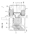
- a projection portion 20A is formed at a position contacting with the outer side surface of the anode cylinder 11, on a surface (hereinafter called a rear surface) of the magnet ring opposing to the anode cylinder 11.
- Fig. 18 is a sectional diagram which shows a part of the magnet ring 20 and also shows the lower surface side of this part.
- the projection portion 30A is formed in a rail shape so as to continue along the circumferential direction of the magnet ring 30.
- the projection portion 30A is provided on the inner circumferential side than the outer circumferential end of the magnet ring on the rear surface of the magnet ring 30, most of the magnetic flux generated by the annular magnets 13A, 13B tends to be directed to the inner circumferential side. That is, more magnetic flux flows to the active space 18 at the periphery of the cathode structure 19, whereby the efficiency of a magnetic circuit can be improved.
- both the anode cylinder 11 and the magnet ring 30 can be positioned.
- the distribution of the magnetic field of the active space 18 can be stabilized, so that the stabilization and the improvement of efficiency of the oscillation can be achieved.
- Fig. 19 is a graph showing the relation between the radial direction position of the projection portion 30A and the magnetic flux density, wherein the abscissa represents the radial direction position ( ⁇ ) of the projection portion 30A and the ordinate represents the magnetic flux density (mT).
- P1 is a graph formed by plotting the values of the magnetic flux density in the case where the projection portion 30A is moved radially from a position near a side tube 14 on the anode side to the position of the outer diameter (outer circumferential end) of the magnet ring 30.
- P2 represents a plotted value of the magnetic flux density of the magnet ring 30 having the uniform thickness of the related art.
- the magnetic flux density at the position 50 mm of the outer diameter of the magnet ring 30 is about 204 mT.
- the magnetic flux density becomes about 220 mT in the case where the projection portion 30A is provided in a range from 25 mm to 45 mm in the vicinity of the body 1. That is, the magnetic flux density increases about 7% by providing the projection portion 30A within this range.
- the projection portion 30A may be provided at any position on the inner circumferential side than the outer circumferential end of the magnet ring 30.
- the position is preferably in a range equal to or smaller than 45 mm in a view point of increasing the magnetic flux density.
- the projection portion 30A is desirably provided at the position contacting with the outer side surface of the anode cylinder 11 in the vicinity of the anode cylinder 11. Instead, the projection portion 30A can be provided at the position contacting with the outer periphery of the pole piece 12.
- the positioning of the magnet ring 30 is made possible, whereby the positional deviation in the radial direction of the magnet ring 30 and the annular magnet 13A (13B) can be prevented. Accordingly, as described above, the distribution of the magnetic field of the active space 18 can be stabilized and so the stabilization and the improvement of efficiency of the oscillation can be achieved.
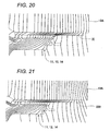
- Fig. 20 is a diagram showing the magnetic field distribution of the magnet ring 30 where the projection portion 30A is provided at the position contacting with the outer side surface of the anode cylinder 11, whilst Fig. 21 is a diagram showing the magnetic field distribution of the magnet ring 20 having the uniform thickness of the related art.
- the projection portion 30A is provided at the position contacting with the outer side surface of the anode cylinder 11 on the rear surface (that is, the surface opposing to the anode cylinder 11) of the magnet ring 30.
- the cut and erected part or the projection portions provided at the outer circumferential end of the magnet ring obstructs the flow of the magnetic flux lines.
- the efficiency of the magnetic circuit can be improved.
- the magnet ring 30 can simultaneously achieve the improvement of the efficiency of the magnetic circuit and the stabilization of the magnetic field distribution in the active space.
- the projection portion 30A is formed in the rail shape so as to continue along the circumferential direction of the magnet ring 30 (concentric continuous rail), the shape of the projection portion is not limited thereto.
- a plurality of projection portions 20B each formed in a mountain shape may be disposed along the circumferential direction of the magnet ring 30.
- the projection portions are also provided on the inner circumferential side than the outer circumferential end of the magnet ring on the rear surface of the magnet ring 30.
- the projection portions provided on the inner circumferential side are preferably disposed at the position contacting with the outer side surface of the anode cylinder 11.
- the anode cylinder 11 and the magnet ring 30 can be positioned more firmly.
- the mountain-shaped projection portion 30B has a size of the height of 0.2 mm and the diameter of 1 mm on the surface thereof contacting with the magnet, as an example.
- the invention can achieve the improvement of the efficiency of the magnetic circuit and the stabilization of the magnetic field distribution in the active space, and can be applied to a device utilizing a microwave such as a microwave oven.
Landscapes
- Microwave Tubes (AREA)
Applications Claiming Priority (2)
| Application Number | Priority Date | Filing Date | Title |
|---|---|---|---|
| JP2008047975A JP2009205963A (ja) | 2008-02-28 | 2008-02-28 | マグネトロン |
| JP2008091247A JP2009245760A (ja) | 2008-03-31 | 2008-03-31 | マグネトロン |
Publications (2)
| Publication Number | Publication Date |
|---|---|
| EP2096660A2 true EP2096660A2 (de) | 2009-09-02 |
| EP2096660A3 EP2096660A3 (de) | 2010-04-14 |
Family
ID=40433885
Family Applications (1)
| Application Number | Title | Priority Date | Filing Date |
|---|---|---|---|
| EP09152226A Withdrawn EP2096660A3 (de) | 2008-02-28 | 2009-02-06 | Magnetron |
Country Status (2)
| Country | Link |
|---|---|
| US (1) | US8120258B2 (de) |
| EP (1) | EP2096660A3 (de) |
Families Citing this family (1)
| Publication number | Priority date | Publication date | Assignee | Title |
|---|---|---|---|---|
| JP5805842B1 (ja) * | 2014-12-03 | 2015-11-10 | 東芝ホクト電子株式会社 | マグネトロン |
Citations (3)
| Publication number | Priority date | Publication date | Assignee | Title |
|---|---|---|---|---|
| JPS53162654U (de) * | 1977-05-25 | 1978-12-20 | ||
| JPS5584849U (de) * | 1978-12-07 | 1980-06-11 | ||
| JP2002163993A (ja) | 2000-11-22 | 2002-06-07 | Sanyo Electric Co Ltd | マグネトロン |
Family Cites Families (8)
| Publication number | Priority date | Publication date | Assignee | Title |
|---|---|---|---|---|
| JPS53111272A (en) * | 1977-03-09 | 1978-09-28 | Matsushita Electronics Corp | Magnetron unit |
| JPS5935497B2 (ja) * | 1979-02-28 | 1984-08-29 | 株式会社東芝 | マグネトロン |
| US4395657A (en) * | 1979-12-21 | 1983-07-26 | Tokyo Shibaura Denki Kabushiki Kaisha | Magnetron unit with a magnetic field compensating means |
| JPS5721050A (en) * | 1980-07-14 | 1982-02-03 | Hitachi Ltd | Magnetron |
| KR900009011B1 (ko) * | 1986-10-06 | 1990-12-17 | 가부시끼가이샤 도시바 | 전자레인지용 마그네트론 |
| JPH06267443A (ja) | 1993-03-17 | 1994-09-22 | Toshiba Corp | マグネトロン |
| JP4006980B2 (ja) * | 2001-11-09 | 2007-11-14 | 松下電器産業株式会社 | マグネトロン装置 |
| KR100651905B1 (ko) * | 2005-03-29 | 2006-12-01 | 엘지전자 주식회사 | 마그네트론 |
-
2009
- 2009-02-06 EP EP09152226A patent/EP2096660A3/de not_active Withdrawn
- 2009-02-19 US US12/388,822 patent/US8120258B2/en active Active
Patent Citations (3)
| Publication number | Priority date | Publication date | Assignee | Title |
|---|---|---|---|---|
| JPS53162654U (de) * | 1977-05-25 | 1978-12-20 | ||
| JPS5584849U (de) * | 1978-12-07 | 1980-06-11 | ||
| JP2002163993A (ja) | 2000-11-22 | 2002-06-07 | Sanyo Electric Co Ltd | マグネトロン |
Also Published As
| Publication number | Publication date |
|---|---|
| US20090218949A1 (en) | 2009-09-03 |
| EP2096660A3 (de) | 2010-04-14 |
| US8120258B2 (en) | 2012-02-21 |
Similar Documents
| Publication | Publication Date | Title |
|---|---|---|
| JP2019022312A (ja) | モータ製造方法及びモータ | |
| KR100685507B1 (ko) | 진공 밸브 | |
| US7385354B2 (en) | Multi-beam klystron apparatus | |
| EP2096660A2 (de) | Magnetron | |
| KR100252839B1 (ko) | 진공밸브 | |
| US7731108B2 (en) | Electromagnetic fuel injection valve | |
| US20080023445A1 (en) | Switching Contfact for Vacuum Interrupters | |
| JP2023533106A (ja) | 電子膨張弁 | |
| CN101521134B (zh) | 磁控管 | |
| US6281623B1 (en) | Core for deflecting yoke | |
| WO2018180636A1 (ja) | モータ | |
| JP2010118293A (ja) | 真空バルブ | |
| US9000669B2 (en) | Magnetron and microwave utilization device | |
| JP5404317B2 (ja) | 真空バルブ | |
| JP2009245760A (ja) | マグネトロン | |
| CN222320081U (zh) | 一种真空灭弧室的外壳组件和真空灭弧室 | |
| US20240234059A1 (en) | Vacuum interrupter | |
| JP5562577B2 (ja) | マグネトロン | |
| JP2018106977A (ja) | マルチビームクライストロン | |
| JP2002163993A (ja) | マグネトロン | |
| JP5210789B2 (ja) | 真空バルブ | |
| EP4657484A1 (de) | Vakuumschalter | |
| JP7615414B1 (ja) | 真空バルブ | |
| US20190295758A1 (en) | Magnetic core | |
| US20230154705A1 (en) | Vacuum interrupter |
Legal Events
| Date | Code | Title | Description |
|---|---|---|---|
| PUAI | Public reference made under article 153(3) epc to a published international application that has entered the european phase |
Free format text: ORIGINAL CODE: 0009012 |
|
| AK | Designated contracting states |
Kind code of ref document: A2 Designated state(s): AT BE BG CH CY CZ DE DK EE ES FI FR GB GR HR HU IE IS IT LI LT LU LV MC MK MT NL NO PL PT RO SE SI SK TR |
|
| AX | Request for extension of the european patent |
Extension state: AL BA RS |
|
| PUAL | Search report despatched |
Free format text: ORIGINAL CODE: 0009013 |
|
| AK | Designated contracting states |
Kind code of ref document: A3 Designated state(s): AT BE BG CH CY CZ DE DK EE ES FI FR GB GR HR HU IE IS IT LI LT LU LV MC MK MT NL NO PL PT RO SE SI SK TR |
|
| AX | Request for extension of the european patent |
Extension state: AL BA RS |
|
| 17P | Request for examination filed |
Effective date: 20101014 |
|
| 17Q | First examination report despatched |
Effective date: 20101112 |
|
| AKX | Designation fees paid |
Designated state(s): DE FR GB |
|
| STAA | Information on the status of an ep patent application or granted ep patent |
Free format text: STATUS: THE APPLICATION IS DEEMED TO BE WITHDRAWN |
|
| 18D | Application deemed to be withdrawn |
Effective date: 20150325 |