EP2096701B1 - Pile à combustible, bloc de piles à combustible, et procédé de fabrication de pile à combustible - Google Patents
Pile à combustible, bloc de piles à combustible, et procédé de fabrication de pile à combustible Download PDFInfo
- Publication number
- EP2096701B1 EP2096701B1 EP08018998.8A EP08018998A EP2096701B1 EP 2096701 B1 EP2096701 B1 EP 2096701B1 EP 08018998 A EP08018998 A EP 08018998A EP 2096701 B1 EP2096701 B1 EP 2096701B1
- Authority
- EP
- European Patent Office
- Prior art keywords
- cross
- outer periphery
- frames
- electrolyte membrane
- fuel cell
- Prior art date
- Legal status (The legal status is an assumption and is not a legal conclusion. Google has not performed a legal analysis and makes no representation as to the accuracy of the status listed.)
- Active
Links
Images







Classifications
-
- H—ELECTRICITY
- H01—ELECTRIC ELEMENTS
- H01M—PROCESSES OR MEANS, e.g. BATTERIES, FOR THE DIRECT CONVERSION OF CHEMICAL ENERGY INTO ELECTRICAL ENERGY
- H01M8/00—Fuel cells; Manufacture thereof
- H01M8/10—Fuel cells with solid electrolytes
- H01M8/1004—Fuel cells with solid electrolytes characterised by membrane-electrode assemblies [MEA]
-
- H—ELECTRICITY
- H01—ELECTRIC ELEMENTS
- H01M—PROCESSES OR MEANS, e.g. BATTERIES, FOR THE DIRECT CONVERSION OF CHEMICAL ENERGY INTO ELECTRICAL ENERGY
- H01M8/00—Fuel cells; Manufacture thereof
- H01M8/02—Details
- H01M8/0271—Sealing or supporting means around electrodes, matrices or membranes
- H01M8/0273—Sealing or supporting means around electrodes, matrices or membranes with sealing or supporting means in the form of a frame
-
- H—ELECTRICITY
- H01—ELECTRIC ELEMENTS
- H01M—PROCESSES OR MEANS, e.g. BATTERIES, FOR THE DIRECT CONVERSION OF CHEMICAL ENERGY INTO ELECTRICAL ENERGY
- H01M8/00—Fuel cells; Manufacture thereof
- H01M8/02—Details
- H01M8/0271—Sealing or supporting means around electrodes, matrices or membranes
- H01M8/0276—Sealing means characterised by their form
-
- H—ELECTRICITY
- H01—ELECTRIC ELEMENTS
- H01M—PROCESSES OR MEANS, e.g. BATTERIES, FOR THE DIRECT CONVERSION OF CHEMICAL ENERGY INTO ELECTRICAL ENERGY
- H01M8/00—Fuel cells; Manufacture thereof
- H01M8/02—Details
- H01M8/0271—Sealing or supporting means around electrodes, matrices or membranes
- H01M8/028—Sealing means characterised by their material
- H01M8/0284—Organic resins; Organic polymers
-
- H—ELECTRICITY
- H01—ELECTRIC ELEMENTS
- H01M—PROCESSES OR MEANS, e.g. BATTERIES, FOR THE DIRECT CONVERSION OF CHEMICAL ENERGY INTO ELECTRICAL ENERGY
- H01M8/00—Fuel cells; Manufacture thereof
- H01M8/02—Details
- H01M8/0271—Sealing or supporting means around electrodes, matrices or membranes
- H01M8/0286—Processes for forming seals
-
- H—ELECTRICITY
- H01—ELECTRIC ELEMENTS
- H01M—PROCESSES OR MEANS, e.g. BATTERIES, FOR THE DIRECT CONVERSION OF CHEMICAL ENERGY INTO ELECTRICAL ENERGY
- H01M8/00—Fuel cells; Manufacture thereof
- H01M8/24—Grouping of fuel cells, e.g. stacking of fuel cells
- H01M8/241—Grouping of fuel cells, e.g. stacking of fuel cells with solid or matrix-supported electrolytes
- H01M8/242—Grouping of fuel cells, e.g. stacking of fuel cells with solid or matrix-supported electrolytes comprising framed electrodes or intermediary frame-like gaskets
-
- H—ELECTRICITY
- H01—ELECTRIC ELEMENTS
- H01M—PROCESSES OR MEANS, e.g. BATTERIES, FOR THE DIRECT CONVERSION OF CHEMICAL ENERGY INTO ELECTRICAL ENERGY
- H01M8/00—Fuel cells; Manufacture thereof
- H01M8/24—Grouping of fuel cells, e.g. stacking of fuel cells
- H01M8/2465—Details of groupings of fuel cells
- H01M8/2483—Details of groupings of fuel cells characterised by internal manifolds
-
- H—ELECTRICITY
- H01—ELECTRIC ELEMENTS
- H01M—PROCESSES OR MEANS, e.g. BATTERIES, FOR THE DIRECT CONVERSION OF CHEMICAL ENERGY INTO ELECTRICAL ENERGY
- H01M8/00—Fuel cells; Manufacture thereof
- H01M8/10—Fuel cells with solid electrolytes
- H01M2008/1095—Fuel cells with polymeric electrolytes
-
- Y—GENERAL TAGGING OF NEW TECHNOLOGICAL DEVELOPMENTS; GENERAL TAGGING OF CROSS-SECTIONAL TECHNOLOGIES SPANNING OVER SEVERAL SECTIONS OF THE IPC; TECHNICAL SUBJECTS COVERED BY FORMER USPC CROSS-REFERENCE ART COLLECTIONS [XRACs] AND DIGESTS
- Y02—TECHNOLOGIES OR APPLICATIONS FOR MITIGATION OR ADAPTATION AGAINST CLIMATE CHANGE
- Y02E—REDUCTION OF GREENHOUSE GAS [GHG] EMISSIONS, RELATED TO ENERGY GENERATION, TRANSMISSION OR DISTRIBUTION
- Y02E60/00—Enabling technologies; Technologies with a potential or indirect contribution to GHG emissions mitigation
- Y02E60/30—Hydrogen technology
- Y02E60/50—Fuel cells
-
- Y—GENERAL TAGGING OF NEW TECHNOLOGICAL DEVELOPMENTS; GENERAL TAGGING OF CROSS-SECTIONAL TECHNOLOGIES SPANNING OVER SEVERAL SECTIONS OF THE IPC; TECHNICAL SUBJECTS COVERED BY FORMER USPC CROSS-REFERENCE ART COLLECTIONS [XRACs] AND DIGESTS
- Y02—TECHNOLOGIES OR APPLICATIONS FOR MITIGATION OR ADAPTATION AGAINST CLIMATE CHANGE
- Y02P—CLIMATE CHANGE MITIGATION TECHNOLOGIES IN THE PRODUCTION OR PROCESSING OF GOODS
- Y02P70/00—Climate change mitigation technologies in the production process for final industrial or consumer products
- Y02P70/50—Manufacturing or production processes characterised by the final manufactured product
-
- Y—GENERAL TAGGING OF NEW TECHNOLOGICAL DEVELOPMENTS; GENERAL TAGGING OF CROSS-SECTIONAL TECHNOLOGIES SPANNING OVER SEVERAL SECTIONS OF THE IPC; TECHNICAL SUBJECTS COVERED BY FORMER USPC CROSS-REFERENCE ART COLLECTIONS [XRACs] AND DIGESTS
- Y10—TECHNICAL SUBJECTS COVERED BY FORMER USPC
- Y10T—TECHNICAL SUBJECTS COVERED BY FORMER US CLASSIFICATION
- Y10T29/00—Metal working
- Y10T29/49—Method of mechanical manufacture
- Y10T29/49002—Electrical device making
- Y10T29/49108—Electric battery cell making
- Y10T29/4911—Electric battery cell making including sealing
Definitions
- the present invention relates to a fuel cell, a fuel cell stack, and a method for manufacturing a fuel cell.
- a fuel cell stack has a structure formed by stacking a number of fuel cells.
- a stack of the number of fuel cells is fastened by end plates arranged on both sides in the stacking direction.
- the fuel cell includes a membrane electrode assembly (hereinafter abbreviated as "MEA").
- MEA includes an electrolyte membrane and a pair of electrodes.
- the pair of electrodes are arranged on both sides of the electrolyte membrane in the thickness direction.
- One of the pair of electrodes is a fuel electrode, and the other is an oxygen electrode.
- the fuel electrode is supplied with fuel gas such as hydrogen and hydrocarbon.
- the oxygen electrode is supplied with oxidant gas such as oxygen and air.
- the supplied gas, the electrolyte membrane, and the electrodes are subjected to an electrochemical reaction at three phase boundary to generate electricity.
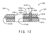
- FIG. 12 shows a partial sectional view of the fuel cell disclosed in the document. An outer periphery portion of the fuel cell is shown in FIG. 12 .
- a fuel cell 100 includes an MEA 101 and a gasket 102.
- the MEA 101 includes an electrolyte membrane 101a and a pair of electrodes 101b and 101c.
- the pair of electrodes 101b and 101c are arranged on both surfaces in the thickness direction of the electrolyte membrane 101a.
- the gasket 102 has a three-layer structure formed by stacking an elastic layer 102a, a shape preservation layer 102b, and a thermal cross-linking layer 102c.
- the thermal cross-linking layer 102c bends and extends in an L-shape. Specifically, the thermal cross-linking layer 102c extends from a thickness direction gap C100 between the electrolyte membrane 101a and the shape preservation layer 102b to a surface extending direction gap C101 between the elastic layer 102a as well as the shape preservation layer 102b and the electrode 101b. In a thickness direction end portion of the thermal cross-linking layer 102c, a rib 102d is formed.
- a method for manufacturing the fuel cell 100 includes a gasket original sheet preparation step, a gasket original sheet punching step, an in-cavity arrangement step, and a cross-linking step.
- FIG. 13 shows a schematic view of the gasket original sheet preparation step.
- FIG. 14 shows a schematic view of the gasket original sheet punching step.
- FIG. 15 shows a schematic view of the in-cavity arrangement step.
- an original sheet of the gasket 102 having the three-layer structure is prepared.
- the original sheet of the gasket 102 is formed by stacking the elastic layer 102a, the shape preservation layer 102b, and the uncross-linked thermal cross-linking layer 102c.
- the gasket original sheet punching step as shown in FIG. 14 , a hole such as a manifold hole 103 is punched out in a predetermined portion of the original sheet of the gasket 102.
- the MEA 101 and the original sheet of the gasket 102 are stacked and arranged in a cavity of a metal mold 104.
- the thermal cross-linking layer 102c is arranged only in the thickness direction gap C100.
- a mold clamping of the metal mold 104 is performed.
- the thermal cross-linking layer 102c is compressed in the thickness direction by the mold clamping. Therefore, the thermal cross-linking layer 102c flows to spill out in the surface extending direction, and is filled in the surface extending direction gap C101 as shown with white arrows in FIG. 15 .
- the thermal cross-linking layer 102c is cross-linked.
- the fuel cell 100 is manufactured.
- the thermal cross-linking layer 102c and the electrolyte membrane 101a are subjected to cross-linking adhesion. Therefore, the thermal cross-linking layer 102c and the electrolyte membrane 101a are firmly joined. Thus, a crossover due to separation of the electrolyte membrane 101a and the gasket 102 can be suppressed.
- an end surface F100 of the electrolyte membrane 101a is exposed to the manifold hole 103, as shown in FIG. 12 . Therefore, there has been a possibility of a product due to decomposition of the electrolyte membrane 101a, such as a fluoride and a sulfonic acid, leaking from the end surface F100.
- Japanese Patent Application Publication No. JP-A-9-199145 discloses a fuel cell in which an outer periphery portion of an electrolyte membrane is sealed with an epoxy adhesive.
- an end surface of the electrolyte membrane is covered by the adhesive. Therefore, the possibility of a product leaking from the end surface of the electrolyte membrane is small.
- JP-A-2007-157420 discloses a fuel cell in which an outer periphery portion of an electrolyte membrane is sealed with an annular ribbon having a thermoplastic resin layer.
- an end surface of the electrolyte membrane is covered by the annular ribbon. Therefore, the possibility of a product leaking from the end surface of the electrolyte membrane is small.
- the annular ribbon is sandwiched merely by a pair of gaskets from both sides in the thickness direction. Therefore, the annular ribbon tends to fall from between the pair of gaskets. Also, there is a possibility of the thermoplastic resin layer of the annular ribbon deforming due to heat. Therefore, the thermoplastic resin layer may separate from the end surface of the electrolyte membrane due to heat. Thus, the sealability at the end surface of the electrolyte membrane may deteriorate.
- a fuel cell, a fuel cell stack, and a method for manufacturing a fuel cell according to some aspects of the present invention have been completed in view of the problems described above.
- the outer periphery portion of the electrolyte membrane is accommodated in the membrane accommodating portion of the first cross-linking adhesive member. Therefore, an external leak of a product due to decomposition of the electrolyte membrane, such as a fluoride and a sulfonic acid, via an end surface of the outer periphery portion of the electrolyte membrane can be suppressed.
- the outer periphery portion of the electrolyte membrane is subjected to cross-linking adhesion with the first cross-linking adhesive member. Therefore, the outer periphery portion of the electrolyte membrane hardly falls from the membrane accommodating portion of the first cross-linking adhesive member. In this manner, the fuel cell of the present aspect has high sealability and adhesiveness between the outer periphery portion of the electrolyte membrane and the first cross-linking adhesive member.
- the first intermediate portion of the first cross-linking adhesive member is arranged between the pair of frames.
- the pair of frames are subjected to cross-linking adhesion with the first cross-linking adhesive member. Therefore, the fuel cell of the present aspect has high sealability and adhesiveness between the pair of frames and the first cross-linking adhesive member.
- the first cross-linking adhesive member is formed of rubber. It is therefore less likely that the first cross-linking adhesive member separates from the outer periphery portion of the electrolyte membrane due to heat, unlike in the thermoplastic resin of the annular ribbon of the fuel cell of Japanese Patent Application Publication No. JP-A-2007-157420 mentioned above.
- the first cross-linking adhesive member is formed of rubber, and therefore is highly water-repellent. Thus, moisture hardly reaches an adhesion boundary surface between the outer periphery portion of the electrolyte membrane and the first cross-linking adhesive member and an adhesion boundary surface between the pair of frames and the first cross-linking adhesive member. That is, the sealability and the adhesiveness are hardly degraded between the outer periphery portion of the electrolyte membrane and the first cross-linking adhesive member and between the pair of frames and the first cross-linking adhesive member.
- the first cross-linking adhesive member is formed of rubber, and therefore has a wide elastic deformation region.
- the first cross-linking adhesive member can easily follow swelling and shrinkage deformation of the electrolyte membrane.
- the difference in deformation amount between the electrolyte membrane and the pair of frames can be easily offset by the first cross-linking adhesive member.
- the sealability and the adhesiveness between the outer periphery portion of the electrolyte membrane and the first cross-linking adhesive member are hardly degraded in this regard as well.
- the electrolyte membrane i.e., the MEA
- the pair of frames can be firmly connected via the first cross-linking adhesive member.
- the gasket and the second cross-linking adhesive member are subjected to cross-linking adhesion.
- the frames and the second cross-linking adhesive member are subjected to cross-linking adhesion. Therefore, the sealability and the adhesiveness between the gasket and the second cross-linking adhesive member and between the frames and the second cross-linking adhesive member are high.
- the second cross-linking adhesive member is formed of rubber, and therefore is highly water-repellent. Thus, moisture hardly reaches an adhesion boundary surface between the gasket and the second cross-linking adhesive member and an adhesion boundary surface between the frames and the second cross-linking adhesive member. That is, the sealability and the adhesiveness between the gasket and the second cross-linking adhesive member and between the frames and the second cross-linking adhesive member are hardly degraded.
- the second cross-linking adhesive member is formed of rubber, and therefore has a wide elastic deformation region.
- the difference in deformation amount between the gasket and the frames can be easily offset.
- the sealability and the adhesiveness between the gasket and the second cross-linking adhesive member and between the frames and the second cross-linking adhesive member are hardly degraded in this regard as well. With this configuration, the gasket and the frames can be firmly connected via the second cross-linking adhesive member.
- Embodiments of a fuel cell, a fuel cell stack, and a method for manufacturing a fuel cell of the present invention will be described below.
- FIG. 1 shows a partial sectional view of the fuel cell stack of this embodiment in the stacking direction.
- FIG. 2 shows an exploded view of a fuel cell and a separator of the fuel cell stack.
- a fuel cell stack 10 of this embodiment includes a fuel cell 1, separators 90U and 90D, and an adhesive member 91.
- the configuration of the fuel cell 1 will be described later in detail.
- the separator 90U is formed of metal, and has a rectangular thin plate shape with unevenness. Gas flow paths 900U are formed in the separator 90U by the uneven shape.
- the separator 90U is arranged above an arbitrary fuel cell 1 (specifically, above a gas diffusion layer 4U described later).
- the separator 90D is formed of metal, and has a rectangular thin plate shape with unevenness. Gas flow paths 900D are formed in the separator 90D by the uneven shape.
- the separator 90D is arranged below an arbitrary fuel cell 1 (specifically, below a gas diffusion layer 4D described later). That is, the arbitrary fuel cell 1 is sandwiched in the vertical direction by the pair of separators 90U and 90D.
- a number of unit structures of the separator 90U, the fuel cell 1, and the separator 90D are stacked in the vertical direction with adhesive members 91 formed of olefin thermoplastic resin therebetween.
- the fuel cell stack 10 has manifold holes 92L and 92R.
- the manifold holes 92L and 92R penetrate separator 90U and 90D and the fuel cell 1 to the stacking direction.
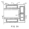
- FIG. 3A shows an upper surface view of the fuel cell of this embodiment.
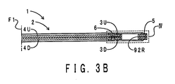
- FIG. 3B shows a sectional view along line B-B of FIG. 3A .
- FIGS. 3A and 3B show the right half portion of the fuel cell 1 with respect to a horizontal direction center plane F1.
- the fuel cell 1 is symmetric with respect to the horizontal direction center plane F1.
- FIG. 4 shows an enlarged view of a frame IV of FIG. 3B .
- the fuel cell 1 of this embodiment includes an MEA 2, a pair of frames 3U and 3D, a pair of gas diffusion layers 4U and 4D, a gasket 5, and a first cross-linking adhesive member 6.
- the MEA 20 includes an electrolyte membrane 20 and a pair of electrodes (not shown).
- the electrolyte membrane 20 is an ion exchange membrane.
- the electrolyte membrane 20 is formed of fluororesin, and has a rectangular thin membrane shape.
- the electrolyte membrane 20 has proton conductivity.
- the pair of electrodes are formed of platinum, and are applied on upper and lower surfaces of the electrolyte membrane 20. Note that the pair of electrodes are not applied on the upper and lower surfaces of an outer periphery portion 200 of the electrolyte membrane 20.
- a method of applying the electrode will be briefly described. First, carbon powder carrying platinum is dispersed in an appropriate organic solvent. Next, an appropriate amount of an electrolyte solution is added to the organic solvent dispersed with the carbon powder to prepare a paste. Then, the paste is screen-printed on the upper and lower surfaces of the electrolyte membrane 20. Thus, the pair of electrodes are applied to the upper and lower surfaces of the electrolyte membrane 20.
- the pair of gas diffusion layers 4U and 4D are respectively formed of carbon cloth formed by weaving of carbon fiber.
- the pair of gas diffusion layers 4U and 4D respectively have rectangular sheet shapes.
- the gas diffusion layer 4U is arranged above the MEA 2.
- the gas diffusion layers 4D is arranged below the MEA 2.
- the pair of frames 3U and 3D are respectively formed of olefin or ester resin, and have rectangular frame shapes. Between a frame inner periphery portion 30U of the frame 3U and a frame inner periphery portion 30D of the frame 3D, the outer periphery portion 200 of the electrolyte membrane 20 is indirectly sandwiched with the first cross-linking adhesive member 6 described later therebetween.
- the gas diffusion layer 4U is arranged inside the frame 3U. Between the frame inner periphery portion 30U of the frame 3U and an outer periphery portion 40U of the gas diffusion layer 4U, a gap CU is formed.
- the gas diffusion layers 4D is arranged inside the frame 3D. Between the frame inner periphery portion 30D of the frame 3D and an outer periphery portion 40D of the gas diffusion layers 4D, a gap CD is formed. An outer periphery portion 31U of the frame 3U and an outer periphery portion 31D of the frame 3D are connected via an adhesive member 32 formed of olefin thermoplastic resin.
- the gasket 5 is formed of silicone rubber, and has a rectangular frame shape.
- the gasket 5 is arranged to cover the pair of frames 3U and 3D.
- the gasket 5 also extends inside the pair of frames 3U and 3D.
- the gasket 5 is present in the respective gaps CU and CD.
- the gasket 5 is integrally formed with ribs 50U (shaded in FIG. 3A for clear illustration) and 50D and holding frame portions 51U and 51D.
- the ribs 50U and 50D are arranged in the circumference of a hole such as the manifold hole 92R.
- the rib 50U is arranged above the frame 3U. In other words, the rib 50U is supported by the frame 3U from below.
- the rib 50D is arranged below the frame 3D.
- the rib 50D is supported by the frame 3D from above. As shown in FIG. 2 , the rib 50U and the rib 50D are in elastic contact with a lower surface of the separator 90U and an upper surface of the separator 90D, respectively.
- the holding frame portion 51U is arranged above the outer periphery portion 40U of the gas diffusion layer 4U.
- the holding frame portion 51D is arranged below the outer periphery portion 40D of the gas diffusion layer 4D. That is, the pair of holding frame portions 51U and 51D hold the gas diffusion layers 4U and 4D in the vertical direction.
- the first cross-linking adhesive member 6 is mounted between the outer periphery portion 200 of the electrolyte membrane 20 and the pair of gas diffusion layers 4U and 4D. Also, the first cross-linking adhesive member 6 is provided between the outer periphery portion 200 of the electrolyte membrane 20 and the gasket 5. Also, the first cross-linking adhesive member 6 is mounted between the outer periphery portion 200 of the electrolyte membrane 20 and the pair of frames 3U and 3D.
- the first cross-linking adhesive member 6 includes a pair of sheet members 6U and 6D.
- the pair of sheet members 6U and 6D are respectively formed of ethylene-propylene-diene rubber (EPDM), and have thin film shapes.
- the sheet member 6U is arranged in a rectangular frame shape to frame the upper surface of the outer periphery portion 200 of the electrolyte membrane 20.
- the sheet member 6D is arranged in a rectangular frame shape to frame the lower surface of the outer periphery portion 200 of the electrolyte membrane 20.
- the first cross-linking adhesive member 6 includes a membrane accommodating portion 60 and a first intermediate portion 61.
- the membrane accommodating portion 60 and the first intermediate portion 61 are formed by the pair of sheet members 6U and 6D.
- the membrane accommodating portion 60 has a pouch shape which is open toward the inside (left side in FIG. 4 ) in the surface extending direction (direction in which the surface extends approximately orthogonally with respect to the stacking direction of the fuel cell 1).
- a portion of the sheet member 6U forming an upper wall of the membrane accommodating portion 60 is disposed between the outer periphery portion 200 of the electrolyte membrane 20 and the outer periphery portion 40U of the gas diffusion layer 4U, between the outer periphery portion 200 and the gasket 5, and between the outer periphery portion 200 and the frame inner periphery portion 30U of the frame 3U in the order from the inside to the outside in the surface extending direction (left to right in FIG. 4 ).
- the sheet member 6U is subjected to cross-linking adhesion with the outer periphery portion 200 of the electrolyte membrane 20, the outer periphery portion 40U of the gas diffusion layer 4U, the gasket 5, and the frame inner periphery portion 30U of the frame 3U.
- the portion of the sheet member 6U between the outer periphery portion 200 of the electrolyte membrane 20 and the outer periphery portion 40U of the gas diffusion layer 4U is a second intermediate portion 600U.
- a portion of the sheet member 6D forming a lower wall of the membrane accommodating portion 60 is disposed between the outer periphery portion 200 of the electrolyte membrane 20 and the outer periphery portion 40D of the gas diffusion layer 4D, between the outer periphery portion 200 and the gasket 5, and between the outer periphery portion 200 and the frame inner periphery portion 30D of the frame 3D in the order from the inside to the outside in the surface extending direction.
- the sheet member 6D is subjected to cross-linking adhesion with the outer periphery portion 200 of the electrolyte membrane 20, the outer periphery portion 40D of the gas diffusion layer 4D, the gasket 5, and the frame inner periphery portion 30D of the frame 3D.
- the portion of the sheet member 6D between the outer periphery portion 200 of the electrolyte membrane 20 and the outer periphery portion 40D of the gas diffusion layer 4D is a second intermediate portion 600D.
- the first intermediate portion 61 is arranged outside the membrane accommodating portion 60 in the surface extending direction.
- the first intermediate portion 61 is interposed between the pair of frames 3U and 3D. Portions of the sheet members 6U and 6D forming the first intermediate portion 61 are subjected to cross-linking adhesion with the pair of frames 3U and 3D. The portions of the sheet members 6U and 6D forming the first intermediate portion 61 are subjected to cross-linking adhesion with each other. Therefore, the membrane accommodating portion 60 is sealed from the outside in the surface extending direction.
- the method for manufacturing the fuel cell 1 of this embodiment includes a sub-assembly arrangement step and an integration step.
- FIG. 5 shows a schematic view of a first half of the sub-assembly arrangement step of the method for manufacturing the fuel cell of this embodiment.
- FIG. 6 shows a schematic view of a second half of the step.
- FIG. 7 shows a schematic view of an integration step of the method for manufacturing the fuel cell of this embodiment. Note that FIG. 5 and the subsequent drawings all show a portion of the fuel cell 1 corresponding to the area inside the frame IV of FIG. 4 .
- a sub-assembly SA is first arranged in a cavity C1 of a metal mold 93.
- the sub-assembly SA includes the MEA 2, the pair of frames 3U and 3D, the gas diffusion layers 4U and 4D, the first cross-linking adhesive member 6, and the adhesive member 32. Note that the sheet members 6U and 6D constituting the first cross-linking adhesive member 6 are in an uncross-linked state.
- the cavity C1 has a shape corresponding to the gasket 5 of FIG. 4 . That is, in a mold surface 930U of an upper mold 93U of the metal mold 93, a rib indentation portion 931U corresponding to the rib 50U of FIG. 4 is provided.
- the mold surface 930U is provided with a holding frame portion indentation portion 932U corresponding to the holding frame portion 51U of FIG. 4 .
- the mold surface 930U is also provided with a manifold hole protrusion portion 933U corresponding to the manifold hole 92R of FIG. 4 .
- a rib indentation portion 931D corresponding to the rib 50D of FIG. 4 is provided in a mold surface 930D of a lower mold 93D of the metal mold 93.
- the mold surface 930D is provided with a holding frame portion indentation portion 932D corresponding to the holding frame portion 51D of FIG. 4 .
- the mold surface 930D is also provided with a manifold hole protrusion portion 933D corresponding to the manifold hole 92R of FIG. 4 .
- mold clamping of the metal mold 93 is performed following the arrangement of the sub-assembly SA. As shown in FIG. 6 , the mold clamping causes the manifold hole protrusion portion 933U of the upper mold 93U and the manifold hole protrusion portion 933D of the lower mold 93D to make contact.
- the adhesive member 32 is sandwiched by the pair of frames 3U and 3D in the vertical direction.
- the sheet members 6U and 6D are sandwiched by the pair of frames 3U and 3D in the vertical direction.
- the outer periphery portion 200 of the electrolyte membrane 20 is provided in an inside portion in the surface extending direction between the pair of sheet members 6U and 6D.
- the outer periphery portion 200 of the electrolyte membrane 20 is also sandwiched by the pair of frames 3U and 3D in the vertical direction via the sheet members 6U and 6D, respectively.
- the membrane accommodating portion 60 and the first intermediate portion 61 are formed by the first cross-linking adhesive member 6 being sandwiched by the pair of frames 3U and 3D in this manner.
- a cavity exposed portion 201U and a cavity exposed portion 201D are respectively formed in the gap CU portion of the upper surface of the outer periphery portion 200 of the electrolyte membrane 20 and the gap CD portion of the lower surface of the outer periphery portion 200.
- the cavity exposed portions 201U and 201D are accommodated in the membrane accommodating portion 60. Therefore, the cavity exposed portions 201U and 201D are not exposed in the cavity C1.
- An upper surface of the gas diffusion layer 4U is pressed from above by the mold surface 930U of the upper mold 93U.
- a lower surface of the gas diffusion layer 4D is pressed from below by the mold surface 930D of the lower mold 93D. Therefore, the second intermediate portion 600U is sandwiched in the vertical direction by the outer periphery portion 200 of the electrolyte membrane 20 and the outer periphery portion 40U of the gas diffusion layer 4U.
- the second intermediate portion 600D is sandwiched in the vertical direction by the outer periphery portion 200 of the electrolyte membrane 20 and the outer periphery portion 40D of the gas diffusion layer 4D.
- a gasket raw material L1 in a liquid state is first poured in the cavity C1 of the metal mold 93 which is heated to a predetermined temperature.
- the gasket raw material L1 spreads in the cavity C1.
- the adhesive member 32 softens. Cross-linking reactions occur in the sheet members 6U and 6D.
- the metal mold 93 is subsequently cooled.
- the gasket raw material L1 hardens, whereby the gasket 5 shown in FIG. 4 is integrally formed.
- the adhesive member 32 hardens, whereby the outer periphery portion 31U of the frame 3U, the adhesive member 32, and the outer periphery portion 31D of the frame 3D are firmly adhered.
- the sheet member 6U and the outer periphery portion 200 of the electrolyte membrane 20, the sheet member 6U and the outer periphery portion 40U of the gas diffusion layer 4U, the sheet member 6U and the gasket raw material L1 filled in the gap CU, the sheet member 6U and the frame 3U, the sheet member 6D and the outer periphery portion 200 of the electrolyte membrane 20, the sheet member 6D and the outer periphery portion 40D of the gas diffusion layer 4D, the sheet member 6D and the gasket raw material L1 filled in the gap CD, the sheet member 6D and the frame 3D, and the sheet member 6D and the sheet member 6U are respectively subjected to firm cross-linking adhesion.
- the fuel cell 1 of this embodiment shown in FIG. 4 is thus manufactured.
- the outer periphery portion 200 of the electrolyte membrane 20 is accommodated in the membrane accommodating portion 60 of the first cross-linking adhesive member 6. Therefore, an external leak of a product due to decomposition of the electrolyte membrane 20, such as a fluoride and a sulfonic acid, via an end surface of the outer periphery portion 200 of the electrolyte membrane 20 can be suppressed.
- the outer periphery portion 200 of the electrolyte membrane 20 is subjected to cross-linking adhesion with the first cross-linking adhesive member 6.
- the fuel cell 1 of this embodiment has high sealability and adhesiveness between the outer periphery portion 200 of the electrolyte membrane 20 and the first cross-linking adhesive member 6.
- the first intermediate portion 61 of the first cross-linking adhesive member 6 is arranged between the pair of frames 3U and 3D.
- the pair of frames 3U and 3D are subjected to cross-linking adhesion with the first cross-linking adhesive member 6. Therefore, the fuel cell 1 of this embodiment has high sealability and adhesiveness between the pair of frames 3U and 3D and the first cross-linking adhesive member 6.
- the pair of sheet members 6U and 6D are subjected to cross-linking adhesion with each other. Therefore, the first intermediate portion 61 itself has high sealability and adhesiveness.
- the first cross-linking adhesive member 6 is formed of EPDM. Therefore, softening due to heat does not occur. It is thus unlikely that the first cross-linking adhesive member 6 softens and separates from the outer periphery portion 200 of the electrolyte membrane 20 due to heat, unlike in the thermoplastic resin layer of the annular ribbon of the fuel cell of Japanese Patent Application Publication No. JP-A-2007-157420 mentioned above.
- the first cross-linking adhesive member 6 is formed of EPDM, and therefore is highly water-repellent. Thus, moisture hardly reaches an adhesion boundary surface between the outer periphery portion 200 of the electrolyte membrane 20 and the first cross-linking adhesive member 6, an adhesion boundary surface between the pair of frames 3U and 3D and the first cross-linking adhesive member 6, and the portions of the pair of sheet members 6U and 6D constituting the first intermediate portion 61.
- the first cross-linking adhesive member 6 is formed of EPDM, and therefore has a wide elastic deformation region.
- the first cross-linking adhesive member 6 can easily follow swelling and shrinkage deformation of the electrolyte membrane 20.
- the difference in deformation amount between the electrolyte membrane 20 and the pair of frames 3U and 3D can easily be offset.
- the sealability and the adhesiveness between the outer periphery portion 200 of the electrolyte membrane 20 and the first cross-linking adhesive member 6 are hardly degraded in this regard as well.
- the electrolyte membrane 20, i.e., the MEA 2 and the pair of frames 3U and 3D can firmly be connected via the first cross-linking adhesive member 6.
- the second intermediate portions 600U and 600D are arranged between the outer periphery portion 200 of the electrolyte membrane 20 and the outer periphery portions 40U and 40D of the gas diffusion layers 4U and 4D. Therefore, the sealability and the adhesiveness between the membrane accommodating portion 60 of the first cross-linking adhesive member 6 and the outer periphery portions 40U and 40D of the gas diffusion layers 4U and 4D are high.
- the first cross-linking adhesive member 6 is formed of EPDM, and therefore is not softened by heat. It is thus less likely that the membrane accommodating portion 60 of the first cross-linking adhesive member 6 is separated from the outer periphery portions 40U and 40D of the gas diffusion layers 4U and 4D due to heat.
- the first cross-linking adhesive member 6 is formed of EPDM, and therefore is highly water-repellent. Thus, moisture hardly reaches an adhesion boundary surface between the membrane accommodating portion 60 of the first cross-linking adhesive member 6 and the outer periphery portions 40U and 40D of the gas diffusion layers 4U and 4D.
- the first cross-linking adhesive member 6 is formed of EPDM, and therefore has a wide elastic deformation region. Thus, the first cross-linking adhesive member 6 can easily offset the difference in deformation amount between the electrolyte membrane 20 and the gas diffusion layers 4U and 4D. In the fuel cell 1 of this embodiment, the electrolyte membrane 20, i.e., the MEA 2, and the gas diffusion layers 4U and 4D can firmly be connected via the first cross-linking adhesive member 6.
- the gasket 5 integrally includes the holding frame portions 51U and 51D which hold the outer periphery portions 40U and 40D of the gas diffusion layers 4U and 4D from the outside in the thickness direction (stacking direction of the fuel cell 1). Therefore, the gas diffusion layers 4U and 4D and the MEA 2 are hardly separated.
- the ribs 50U and 50D of the gasket 5 are arranged outside the frames 3U and 3D in the thickness direction.
- the ribs 50U and 50D making elastic contact with the separators 90U and 90D, the sealability between the fuel cell 1 and the separators 90U and 90D can be ensured.
- the electrolyte membrane 101a is arranged inside the rib 102d of the fuel cell 100 of the Japanese Patent Application Publication No. JP-A-2002-260693 in the thickness direction. Therefore, the reaction force due to the rib 102d making elastic contact with an opponent member tends to be applied to the electrolyte membrane 101a.
- the rib 102d is formed of rubber, and therefore tends to elastically deform. Therefore, the elastic force on the opponent member tends to be small.
- the ribs 50U and 50D of the fuel cell 1 of this embodiment are arranged outside the frames 3U and 3D in the thickness direction. That is, the ribs 50U and 50D are supported by the frames 3U and 3D from the inside in the thickness direction.
- the frames 3U and 3D have higher rigidity than the gasket 5. Therefore, in the fuel cell 1 of this embodiment, the elastic force on the separators 90U and 90D hardly becomes small.
- the frames 3U and 3D are interposed between the ribs 50U and 50D and the outer periphery portion 200 of the electrolyte membrane 20. Therefore, the reaction force due to the ribs 50U and 50D making elastic contact with the separators 90U and 90D is hardly applied to the outer periphery portion 200 of the electrolyte membrane 20.
- the rib 102d is subjected to compression deformation in the thickness direction when the rib 102d of the fuel cell 100 of the Japanese Patent Application Publication No. JP-A-2002-260693 makes elastic contact with the opponent member.
- the rib 102d is subjected to stretching deformation in the surface extending direction so as to expand the surface extending direction gap C101.
- the electrode 101b is adhered to the inner side of the rib 102d in the surface extending direction.
- the elastic layer 102a and a shape preservation layer 102b are adhered to the outer side of the rib 102d in the surface extending direction. Therefore, when the rib 102d is deformed, there is a possibility of the rib 102d and the electrode 101b, or the rib 102d and the elastic layer 102a as well as the shape preservation layer 102b being separated.
- the ribs 50U and 50D of the fuel cell 1 of this embodiment are formed integrally with the gasket 5 at the time of forming the gasket 5 (see FIG. 7 ). It is therefore less likely that the ribs 50U and 50D fall from the gasket 5 even when the ribs 50U and 50D are deformed.
- the MEA 2 the pair of frames 3U and 3D, the pair of gas diffusion layers 4U and 4D, the gasket 5, and the first cross-linking adhesive member 6 are integrated. Therefore, the fuel cell stack 10 of this embodiment is easily assembled. Also, the assembly error is small.
- the fuel cell 1 having high sealability and adhesiveness between the outer periphery portion 200 of the electrolyte membrane 20 and the first cross-linking adhesive member 6 can be easily manufactured by a simple procedure of arranging the sub-assembly SA in the cavity C1 (sub-assembly arrangement step) and heating while pouring the gasket raw material L1 in the cavity C1 (integration step).
- the fuel cell 1 having high sealability and adhesiveness between the pair of frames 3U and 3D and the first cross-linking adhesive member 6 can be easily manufactured.
- the electrolyte membrane 20, i.e., the MEA 2 and the pair of frames 3U and 3D can be firmly connected via the first cross-linking adhesive member 6.
- the fuel cell 1 having high sealability and adhesiveness between the membrane accommodating portion 60 of the first cross-linking adhesive member 6 and the outer periphery portions 40U and 40D of the gas diffusion layers 4U and 4D can be easily manufactured by providing and cross-linking the second intermediate portions 600U and 600D.
- the electrolyte membrane 20, i.e., the MEA 2 and the gas diffusion layers 4U and 4D can be firmly connected via the first cross-linking adhesive member 6.
- the first cross-linking adhesive member 6 covers the cavity exposed portions 201U and 201D of the electrolyte membrane 20 (see FIG. 6 ) in the sub-assembly arrangement step. Therefore, in the integration step, the flow of the gasket raw material L1 does not directly press the cavity exposed portions 201U and 201D.
- the first cross-linking adhesive member 6 is an elastic body. Therefore, even when the flow of the gasket raw material L1 indirectly presses the cavity exposed portions 201U and 201D via the first cross-linking adhesive member 6 to deform the electrolyte membrane 20, the electrolyte membrane 20 can recover to a predetermined shape by the elastic resilience of the first cross-linking adhesive member 6. Also, it is less likely that the electrolyte membrane 20 falls from between the pair of frames 3U and 3D due to the flow of the gasket raw material L1.
- a difference of a fuel cell of this embodiment from the fuel cell of the first embodiment is that the volume of the gasket is small. Thus, only the difference will be described here.
- FIG. 8 shows a partial sectional view in the thickness direction of the fuel cell of this embodiment. Note that portions corresponding to those of FIG. 4 are denoted by the same reference symbols.
- gaskets 5U and 5D are not integrated, but are independent from each other.
- the gasket 5U is arranged on an upper surface of the frame 3U.
- the gasket 5U has the rib 50U and a base portion 52U.
- the base portion 52U is secured to the upper surface of the frame 3U.
- the rib 50U is provided so as to protrude upward from the base portion 52U.
- the gasket 5D is arranged on a lower surface of the frame 3D.
- the gasket 5D has the rib 50D and a base portion 52D.
- the base portion 52D is secured to the lower surface of the frame 3D.
- the rib 50D is provided so as to protrude downward from the base portion 52D.
- the gaskets 5U and 5D are not present in the gaps CU and CD.
- an exposed portion 202U on the upper surface of the outer periphery portion 200 of the electrolyte membrane 20 is covered by the sheet member 6U. Therefore, the exposed portion 202U is not exposed to the outside of the sheet member 6U from the gap CU.
- an exposed portion 202D on the lower surface of the outer periphery portion 200 of the electrolyte membrane 20 is covered by the sheet member 6D. Therefore, the exposed portion 202D is not exposed to the outside of the sheet member 6D from the gap CD.
- FIG. 9 shows a schematic view of an integration step of a method for manufacturing the fuel cell of this embodiment. Note that portions corresponding to those of FIG. 7 are denoted by the same reference symbols.
- an upper cavity C2U and a lower cavity C2D are separately and individually arranged in the metal mold 93.
- the cavity C2U has a shape corresponding to the gasket 5U of FIG. 8 .
- the cavity C2D has a shape corresponding to the gasket 5D of FIG. 8 .
- the gaskets 5U and 5D of FIG. 8 are formed by pouring the gasket raw material L1 in the cavities C2U and C2D.
- the fuel cell, a fuel cell stack, and the method for manufacturing a fuel cell of this embodiment have advantageous effects similar to those of the fuel cell, the fuel cell stack, and the method for manufacturing a fuel cell of the first embodiment regarding portions having common configurations.
- the first cross-linking adhesive member 6 is formed of EPDM, and therefore is highly water-repellent. Thus, moisture hardly reaches the adhesion boundary surface between the outer periphery portion 200 of the electrolyte membrane 20 and the first cross-linking adhesive member 6, the adhesion boundary surface between the pair of frames 3U and 3D and the first cross-linking adhesive member 6, and the adhesion boundary surface of the pair of gas diffusion layers 4U and 4D and the first cross-linking adhesive member 6. Therefore, it is less likely that the electrolyte membrane 20 is degraded by moisture even if the gaps CU and CD are not intentionally sealed by the gaskets 5U and 5D, as in the fuel cell of this embodiment. Since the gaps CU and CD do not need to be sealed, the usage amount of the gasket raw material L1 can be reduced in the method for manufacturing a fuel cell of this embodiment. Thus, the manufacturing cost of the fuel cell can be reduced.
- the exposed portions 202U and 202D of the electrolyte membrane 20 are covered by the first cross-linking adhesive member 6. Therefore, an external leak of a product due to decomposition of the electrolyte membrane 20, such as a fluoride and a sulfonic acid, via the exposed portions 202U and 202D can be suppressed.
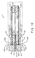
- a difference of a fuel cell of this embodiment from the fuel cell of the first embodiment is that the volume of the gasket is small. Another difference is that a second cross-linking adhesive member is arranged between the frame and the gasket. Thus, only the differences will be described here.
- FIG. 10 shows a partial sectional view in the thickness direction of the fuel cell of this embodiment. Note that portions corresponding to those of FIG. 4 are denoted by the same reference symbols.
- the sheet member 6U and a second cross-linking adhesive member 7U are subjected to cross-linking adhesion with a lower surface of the frame 3U and the upper surface of the frame 3U, respectively.
- the second cross-linking adhesive member 7U is formed of EPDM, and is arranged on the entire upper surface of the frame 3U.
- the sheet member 6D and a second cross-linking adhesive member 7D are arranged on an upper surface of the frame 3D and the lower surface of the frame 3D, respectively.
- the second cross-linking adhesive member 7D is formed of EPDM, and is arranged on the entire lower surface of the frame 3D.
- the membrane accommodating portion 60 includes third intermediate portions 601U and 601D.
- the third intermediate portion 601U is interposed between the outer periphery portion 200 of the electrolyte membrane 20 and the frame inner periphery portion 30U of the frame 3U.
- the third intermediate portion 601D is interposed between the outer periphery portion 200 of the electrolyte membrane 20 and the frame inner periphery portion 30D of the frame 3D.
- the outer periphery portion 200 of the electrolyte membrane 20, the frame inner periphery portions 30U and 30D of the frames 3U and 3D, and the outer periphery portions 40U and 40D of the gas diffusion layers 4U and 4D are stacked in the thickness direction.
- the third intermediate portions 601U and 601 D are interposed between the outer periphery portion 200 of the electrolyte membrane 20 and the frame inner periphery portions 30U and 30D of the frames 3U and 3D.
- Frame inner periphery portions of the second cross-linking adhesive members 7U and 7D are interposed between the frame inner periphery portions 30U and 30D of the frames 3U and 3D and the outer periphery portions 40U and 40D of the gas diffusion layers 4U and 4D.
- the gaskets 5U and 5D are not integrated, but are independent from each other in a similar manner to those in the second embodiment.
- the gasket 5U is arranged on an upper surface of the second cross-linking adhesive member 7U.
- the gasket 5U has the rib 50U and the base portion 52U.
- the base portion 52U is subjected to cross-linking adhesion with the upper surface of the second cross-linking adhesive member 7U.
- the rib 50U is provided so as to protrude upward from the base portion 52U.
- the gasket 5D is arranged on a lower surface of the second cross-linking adhesive member 7D.
- the gasket 5D has the rib 50D and the base portion 52D.
- the base portion 52D is subjected to cross-linking adhesion with the lower surface of the second cross-linking adhesive member 7D.
- the rib 50D is provided so as to protrude downward from the base portion 52D.
- FIG. 11 shows a schematic view of an integration step of a method for manufacturing a fuel cell of this embodiment. Note that portions corresponding to those of FIG. 7 are denoted by the same reference symbols.
- the upper cavity C2U and the lower cavity C2D are separately and individually arranged in the metal mold 93.
- the cavity C2U has a shape corresponding to the gasket 5U of FIG. 10 .
- the cavity C2D has a shape corresponding to the gasket 5D of FIG. 10 .
- the gaskets 5U and 5D of FIG. 10 are formed by pouring the gasket raw material L1 in the cavities C2U and C2D.
- the first cross-linking adhesive member 6 and the second cross-linking adhesive members 7U and 7D cause cross-linking reactions.
- the fuel cell, a fuel cell stack, and the method for manufacturing the fuel cell of this embodiment have advantageous effects similar to those of the fuel cell, the fuel cell stack, and the method for manufacturing a fuel cell of the first embodiment regarding portions having common configurations.
- the gaskets 5U and 5D and the second cross-linking adhesive members 7U and 7D are subjected to cross-linking adhesion.
- the frames 3U and 3D and the second cross-linking adhesive members 7U and 7D are subjected to cross-linking adhesion. Therefore, the sealability and the adhesiveness between the gaskets 5U and 5D and the second cross-linking adhesive members 7U and 7D and between the frames 3U and 3D and the second cross-linking adhesive members 7U and 7D are high.
- the second cross-linking adhesive members 7U and 7D are formed of EPDM, and therefore are highly water-repellent.
- moisture hardly reaches an adhesion boundary surface between the gaskets 5U and 5D and the second cross-linking adhesive members 7U and 7D and an adhesion boundary surface between the frames 3U and 3D and the second cross-linking adhesive members 7U and 7D. That is, the sealability and the adhesiveness between the gaskets 5U and 5D and the second cross-linking adhesive members 7U and 7D and between the frames 3U and 3D and the second cross-linking adhesive members 7U and 7D are hardly degraded.
- the second cross-linking adhesive members 7U and 7D are formed of EPDM, and therefore have wide elastic deformation regions. Thus, the difference in deformation amount between the gaskets 5U and 5D and the frames 3U and 3D can be easily offset.
- the sealability and the adhesiveness between the gaskets 5U and 5D and the second cross-linking adhesive members 7U and 7D and between the frames 3U and 3D and the second cross-linking adhesive members 7U and 7D are hardly degraded in this regard as well.
- the gaskets 5U and 5D and the frames 3U and 3D can be firmly connected via the second cross-linking adhesive members 7U and 7D.
- the outer periphery portion 200 of the electrolyte membrane 20, the frame inner.periphery portions 30U and 30D of the frames 3U and 3D, and the outer periphery portions 40U and 40D of the gas diffusion layers 4U and 4D are stacked in the thickness direction.
- the third intermediate portions 601U and 601D of the membrane accommodating portion 60 of the first cross-linking adhesive member 6 are interposed between the outer periphery portion 200 of the electrolyte membrane 20 and the frame inner periphery portions 30U and 30D of the frames 3U and 3D.
- the third intermediate portions 601U and 601D are subjected to cross-linking adhesion with the outer periphery portion 200 of the electrolyte membrane 20 and the frame inner periphery portions 30U and 30D of the frames 3U and 3D. Therefore, the sealability and the adhesiveness between the third intermediate portions 601U and 601D and the outer periphery portion 200 of the electrolyte membrane 20 are high. In addition, the sealability and the adhesiveness between the third intermediate portions 601U and 601D and the frame inner periphery portions 30U and 30D of the frames 3U and 3D are high.
- the second cross-linking adhesive members 7U and 7D are interposed between the frame inner periphery portions 30U and 30D of the frames 3U and 3D and the outer periphery portions 40U and 40D of the gas diffusion layers 4U and 4D.
- the second cross-linking adhesive members 7U and 7D are subjected to cross-linking adhesion with the frame inner periphery portions 30U and 30D of the frames 3U and 3D and the outer periphery portions 40U and 40D of the gas diffusion layers 4U and 4D. Therefore, the sealability and the adhesiveness between the second cross-linking adhesive members 7U and 7D and the frame inner periphery portions 30U and 30D of the frames 3U and 3D are high. In addition, the sealability and the adhesiveness between the second cross-linking adhesive members 7U and 7D and the outer periphery portions 40U and 40D of the gas diffusion layers 4U and 4D are high.
- the third intermediate portions 601U and 601D are formed of EPDM. It is therefore less likely that the third intermediate portions 601U and 601D separate from the outer periphery portion 200 of the electrolyte membrane 20 and the frame inner periphery portions 30U and 30D of the frames 3U and 3D due to heat.
- the third intermediate portions 601U and 601D are formed of EPDM, and therefore are highly water-repellent. Thus, moisture hardly reaches an adhesion boundary surface between the outer periphery portion 200 of the electrolyte membrane 20 and the third intermediate portions 601U and 601D and an adhesion boundary surface between the frame inner periphery portions 30U and 30D of the frames 3U and 3D and the third intermediate portions 601U and 601D.
- the third intermediate portions 601U and 601D are formed of EPDM, and therefore have wide elastic deformation regions. Thus, the difference in deformation amount between the electrolyte membrane 20 and the frames 3U and 3D can be easily offset. The electrolyte membrane 20 and the frames 3U and 3D can be firmly connected via the third intermediate portions 601U and 601D.
- the second cross-linking adhesive members 7U and 7D are formed of EPDM. It is therefore less likely that the second cross-linking adhesive members 7U and 7D separate from the frame inner periphery portions 30U and 30D of the frames 3U and 3D and the outer periphery portions 40U and 40D of the gas diffusion layers 4U and 4D due to heat.
- the second cross-linking adhesive members 7U and 7D are formed of EPDM, and therefore are highly water-repellent. Thus, moisture hardly reaches an adhesion boundary surface between the frame inner periphery portions 30U and 30D of the frames 3U and 3D and the second cross-linking adhesive members 7U and 7D and an adhesion boundary surface between the outer periphery portions 40U and 40D of the gas diffusion layers 4U and 4D and the second cross-linking adhesive members 7U and 7D.
- the second cross-linking adhesive members 7U and 7D are formed of EPDM, and therefore have wide elastic deformation regions. Thus, the difference in deformation amount between the frames 3U and 3D and the gas diffusion layers 4U and 4D can be easily offset. The frames 3U and 3D and the gas diffusion layers 4U and 4D can be firmly connected via the second cross-linking adhesive members 7U and 7D.
- the outer periphery portion 200 of the electrolyte membrane 20 may not be sandwiched by the pair of frames 3U and 3D. That is, only the first intermediate portion 61 may be sandwiched between the pair of frames 3U and 3D. Accordingly, the fastening force of the fuel cell stack 10 is hardly transmitted to the outer periphery portion 200 of the electrolyte membrane 20. Therefore, the outer periphery portion 200 of the electrolyte membrane 20 is hardly degraded.
- the arrangement method of the first cross-linking adhesive member 6 and the second cross-linking adhesive members 7U and 7D is also not particularly limited.
- the first cross-linking adhesive member 6 and the second cross-linking adhesive members 7U and 7D may be arranged by applying or spraying liquid rubber.
- the material of the pair of frames 3U and 3D is not particularly limited.
- Various resins thermosetting resins and thermoplastic resins
- such as polyimide, polyethylene naphthalate, epoxy resin including glass material, and the like may be used.
- the material has high heat resistance and chemical resistance.
- the material of the gaskets 5U and 5D is not also particularly limited. Fluorine rubber, ethylene-propylene rubber, thermoplastic elastomer, thermosetting silicone resin, thermoplastic resin, or the like may be used other than silicone rubber.
- the material of the separators 90U and 90D is not also particularly limited. Carbon (preferably gas-impermeable dense carbon) or the like may be used other than metal.
- the material of the electrolyte membrane 20 is not also particularly limited. A hydrocarbon (HC) material or the like may be used other than fluororesin.
- the material and the shape of the gas diffusion layers 4U and 4D are not also particularly limited. A paper form is accepted other than the woven cloth form.
- the material of the electrode is not also particularly limited.
- the alloy containing platinum and ruthenium, the alloy containing platinum and nickel, the alloy containing platinum and cobalt, the alloy containing platinum and indium, the alloy containing platinum and iron, the alloy containing platinum and chromium, the alloy containing platinum and manganese, etc. may be used other than platinum.
- At least one cross-linking adhesive member of the first cross-linking adhesive member and the second cross-linking adhesive member may be formed of a cross-linked product of a rubber composition including the following contents of (A) to (D), i.e., formed of rubber.
- cross-linking adhesive member of the first cross-linking adhesive member and the second cross-linking adhesive member
- the rubber component (A) will be described.
- the rubber component of the cross-linking adhesive member one or more selected from a group consisting of ethylene-propylene rubber (EPM), ethylene-propylene-diene rubber (EPDM), acrylonitrile-butadiene rubber (NBR), and hydrogenated acrylonitrile-butadiene rubber (H-NBR) may be used.
- EPM ethylene-propylene rubber
- EPDM ethylene-propylene-diene rubber
- NBR acrylonitrile-butadiene rubber
- H-NBR hydrogenated acrylonitrile-butadiene rubber
- the cross-linking agent (B) As the cross-linking agent, an organic peroxide of which the 1-hour half-life period temperature is lower than or equal to 130°C may be used.
- the "half-life period” refers to time in which the concentration of an organic peroxide becomes half of an initial value.
- the "half-life period temperature” is an index showing the decomposition temperature of an organic peroxide.
- the "1-hour half-life period temperature” is a temperature at which the half-life period becomes 1 hour. That is, the lower the 1-hour half-life period temperature, the easier the decomposition of the organic peroxide at a lower temperature.
- cross-linking can be performed at a lower temperature (specifically, lower than or equal to 130°C) and in a short period of time.
- the cross-linking adhesive member can be used also near the electrolyte membrane.
- the cross-linking agent (B) described above a platinum catalyst is unnecessary in the cross-linking.
- a curing failure due to impurity, dirt, or the like hardly occurs. Therefore, the cross-linking adhesive member is hardly influenced by the operational environment, and is easily handled.
- the organic peroxides of (B) described above include peroxyketal, peroxyester, diacyl peroxide, peroxydicarbonate, and the like.
- at least one of the peroxyketal and the peroxyester of which the 1-hour half-life period temperature is higher than or equal to 100°C is preferably employed, since cross-linking easily occurs at a temperature of approximately 130°C and the rubber composition in which the cross-linking agent is added and kneaded can be handled easily.
- one with a 1-hour half-life period temperature of 110°C or higher is preferable.
- peroxyketal examples include n-butyl 4,4-di (t-butylperoxy) valerate, 2,2-di (t-butylperoxy) butane, 2,2-di (4,4-di (t-butylperoxy) cyclohexyl) propane, 1,1-di (t-butylperoxy) cyclohexane, 1,1-di (t-hexylperoxy) cyclohexane, 1,1-di (t-hexylperoxy) -3,3,5-trimethylcyclohexane, 1,1-di(t-butylperoxy)-2-methylcyclohexane, and the like.
- peroxyester examples include t-butyl peroxybenzoate, t-butyl peroxyacetate, t-hexyl peroxybenzoate, 2,5-dimethyl-2,5-di (benzoylperoxy) hexane, t-butyl peroxy-2-ethylhexyl monocarbonate, t-butyl peroxylaurate, t-butyl peroxyisopropylmonocarbonate, t-butyl peroxy-3,5,5-trimethylhexanoate, t-butyl peroxymaleic acid, t-hexyl peroxyisopropylmonocarbonate, and the like.
- 1,1-di (t-butylperoxy) cyclohexane and t-butyl peroxyacetate are preferable, since the cross-linking agent using them is easily accommodated.
- the amount of the cross-linking agent is preferably greater than or equal to 1 part by weight with respect to 100 parts by weight of the rubber component (A) described above so that the cross-linking reaction progresses sufficiently. In consideration of the storage stability of the prepared rubber composition, it is preferably less than or equal to 5 parts by weight.
- the cross-linking auxiliary agent (C) may appropriately be selected according to the type of the cross-linking agent (B) described above.
- the cross-linking auxiliary agent include a maleimide compound, triallyl cyanurate (TAC), triallyl isocyanurate (TAIC), trimethylolpropane trimethacrylate (TMPT), and the like. Particularly, using the maleimide compound is preferable since the cross-linking speed becomes faster.
- the amount of the cross-linking auxiliary agent is preferably greater than or equal to 0.1 part by weight with respect to 100 parts by weight of the rubber component (A) described above so that the cross-linking reaction progresses sufficiently.
- the amount of the cross-linking auxiliary agent is preferably less than or equal to 3 parts by weight, since the adhesive force decreases when the cross-linking reaction becomes too fast due to a large amount of the cross-linking auxiliary agent.
- Adhesive component (D) Adhesive component
- the adhesive component (D) will be described.
- the melamine compound becomes a methylene donor
- the resorcinol compound becomes a methylene acceptor.
- a methylene group is donated to form a chemical bond between the resorcinol compound and the rubber component as well as an opponent member, whereby the rubber component and the opponent member are adhered.
- a silane coupling agent is included as the adhesive component
- a chemical bond is formed between the rubber component and the opponent member by the silane coupling agent, whereby the two are adhered.
- the adhesive force due to the adhesive component is strong, and the adhesive force hardly decreases even in the operational environment of a fuel cell stack. Thus, even in the case where the fuel cell stack is operated for a long period of time, high sealability is ensured. Accordingly, the operational reliability of the fuel cell stack can be improved.
- the adhesive component (D) is formed of at least one of the resorcinol compound together with the melamine compound and the silane coupling agent. That is, the adhesive component may be only the resorcinol compound and the melamine compound, or only the silane coupling agent. In the case where both the resorcinol compound together with the melamine compound and the silane coupling agent are included, the adhesive force is further improved.
- the resorcinol compound examples include resorcin, modified resorcin formaldehyde resin, resorcin formaldehyde (RF) resin, and the like. A single one or a mixture of two or more of these may be used.
- the modified resorcin formaldehyde resin is preferable in terms of low volatility, low hygroscopicity, and high compatibility with rubber.
- the modified resorcin formaldehyde resin examples include those represented by general formulas (1) to (3) below. One shown by the general formula (1) is particularly preferable. Note that reference symbols "n” all indicate an integer in the general formulas (1) to (3). Reference symbol “R” indicates a hydrocarbon group in the general formula (1).
- reference symbol “R” indicates a hydrocarbon group
- reference symbol “n” indicates an integer
- the amount of the resorcinol compound is preferably greater than or equal to 0.1 part by weight with respect to 100 parts by weight of the rubber component (A) described above. It is more preferably greater than or equal to 0.5 parts by weight.
- the amount of the resorcinol compound is preferably less than or equal to 10 parts by weight, since an excessive amount of the resorcinol compound causes a decrease in the properties of rubber. It is more preferably less than or equal to 5 parts by weight.
- the melamine compound examples include a methylated formaldehyde melamine polymer, hexamethylene tetramine, and the like. One or more of these compounds may be used singly or in combination. These are decomposed by heat in the cross-linking, and supply formaldehyde to the system. Particularly, the methylated formaldehyde melamine polymer is preferable in terms of low volatility, low hygroscopicity, and high compatibility with rubber.
- the methylated formaldehyde melamine polymer represented by a general formula (4) below is preferable, for example.
- the compound ratio of the resorcinol compound and the melamine compound is preferably in a range of 1:0.5 to 1:2 by weight. It is more preferably in a range of 1:0.77 to 1:1.5.
- the compound ratio of the melamine compound with respect to the resorcinol compound is less than 0.5, the tensile strength, the stretch, and the like of the rubber tend to slightly decrease.
- the compound ratio of the melamine compound exceeds 2, the adhesive force reaches a limit. Therefore, further increase in the compound ratio of the melamine compound leads to an increase in cost.
- the silane coupling agent may appropriately be selected in consideration of the adhesiveness and the like from a group of compounds having an epoxy group, an amino group, a vinyl group, or the like as a functional group.
- Examples include vinyltrimethoxysilane, vinyltriethoxysilane, vinyl-tris (2-methoxyethoxy) silane, 3-methacryloxypropyltrimethoxysilane, 3-methacryloxypropyltriethoxysilane, 3-glycidoxypropyltrimethoxysilane, 3-glycidoxypropyltriethoxysilane, 3-glycidoxypropylmethyldiethoxysilane, 2- (3,4-epoxycyclohexyl) ethyltrimethoxysilane, N-2 (aminoethyl) 3-aminopropyltrimethoxysilane, 3-aminopropyltrimethoxysilane, N-phenyl-3-aminopropyltrimethoxysi
- One or more of these compounds may be used singly or in combination. Particularly, when one or more selected from the group of compounds having an epoxy group is used, the adhesive force is improved, and the adhesive force hardly decreases even in the operational environment of a fuel cell stack. Specifically, 3-glycidoxypropyltrimethoxysilane, 3-glycidoxypropyltriethoxysilane, 3-glycidoxypropylmethyldiethoxysilane, 2- (3,4-epoxycyclohexyl) ethyltrimethoxysilane, and the like are preferable.
- the amount of the silane coupling agent is preferably greater than or equal to 0.5 parts by weight with respect to 100 parts by weight of the rubber component (A) described above. It is more preferably greater than or equal to 2 parts by weight.
- the amount of the silane coupling agent is preferably less than or equal to 10 parts by weight, and more preferably, less than or equal to 6 parts by weight.
- the rubber composition of the cross-linking adhesive member may include various additives which are used as additives for general rubber other than the contents of (A) to (D) described above.
- carbon black as a reinforcing agent.
- the grade of the carbon black is not particularly limited, and may appropriately be selected from SAF, ISAF, HAF, MAF, FEF, GPF, SRF, FT, MT, and the like.
- the amount of the carbon black is preferably greater than or equal to 30 parts by weight with respect to 100 parts by weight of the rubber component (A) described above.
- the amount of the carbon black is preferably less than or equal to 150 parts by weight in consideration of the easiness of kneading, forming processability, and the like.
- the softeners include: petroleum-based softeners such as process oil, lubricating oil, paraffin, liquid paraffin, petroleum asphalt, and petrolatum; fatty oil-based softeners such as castor oil, linseed oil, canola oil, and palm oil; waxes such as tall oil, a rubber substitute, beeswax, carnauba wax, and lanolin; linoleic acid; palmitic acid; stearic acid; lauric acid; and the like.
- petroleum-based softeners such as process oil, lubricating oil, paraffin, liquid paraffin, petroleum asphalt, and petrolatum
- fatty oil-based softeners such as castor oil, linseed oil, canola oil, and palm oil
- waxes such as tall oil, a rubber substitute, beeswax, carnauba wax, and lanolin
- linoleic acid palmitic acid
- stearic acid lauric acid
- lauric acid and
- the amount of the softener is preferably up to approximately 40 parts by weight with respect to 100 parts by weight of the rubber component (A) described above.
- the plasticizers include organic acid derivatives such as dioctyl phthalate (DOP) and phosphoric acid derivatives such as tricresyl phosphate.
- the amount of the plasticizer is preferably approximately 40 parts by weight at most with respect to 100 parts by weight of the rubber component (A) described above, in a similar manner to that of the softener.
- the antioxidants include phenolic antioxidants, imidazole-based antioxidants, waxes, and the like, and the amount is preferably approximately 0.5 to 10 parts by weight with respect to 100 parts by weight of the rubber component (A) described above.
- the rubber composition can be prepared by mixing the contents of (A) to (D) described above and the various additives as necessary.
- the respective materials other than the cross-linking agent (B), the cross-linking auxiliary agent (C), and the adhesive component (D) are mixed in advance, and then are kneaded for several minutes at 80 to 140°C. After the kneaded product is cooled, the cross-linking agent (B), the cross-linking auxiliary agent (C), and the adhesive component (D) are added, and are kneaded for 5 to 30 minutes at a roll temperature of 40 to 70°C using a roller such as an open roller, whereby the rubber composition can be prepared.
- the adhesive component (D) may be added at the time of the preparatory mixture.
- the cross-linking adhesive member may be formed of a cross-linked product of rubber composition including the contents of (a) to (c) below, i.e., formed of rubber.
- the rubber component (a) will be described.
- the rubber component of the cross-linking adhesive member one or more selected from a group consisting of EPM, EPDM, NBR, and H-NBR may be used. One or more of these components may be used singly or in combination. These rubber components have low gas permeability. Thus, the sealability is improved.
- the cross-linking agent (b) As the cross-linking agent, an organic peroxide of which the 1-hour half-life period temperature is lower than or equal to 120°C may be used. By using the organic peroxide of which the 1-hour half-life period temperature is lower than or equal to 120°C, cross-linking can be performed at a lower temperature (specifically, lower than or equal to 120°C) and in a short period of time. Thus, the cross-linking adhesive member can be used also near the electrolyte membrane. With the cross-linking agent (b) described above, a platinum catalyst is unnecessary in the cross-linking. In addition, a curing failure due to impurity, dirt, or the like hardly occurs. Therefore, the cross-linking adhesive member is hardly influenced by the operational environment, and is easily handled.
- the organic peroxides of (b) described above include diacyl peroxide, peroxyester, peroxydicarbonate, and the like.
- the diacyl peroxide of which the 1-hour half-life period temperature is higher than or equal to 90°C is preferably employed, since cross-linking easily occurs at approximately 120°C.
- one with a 1-hour half-life period temperature of lower than 110°C or further lower than 100°C is preferable.
- diacyl peroxide examples include benzoyl peroxide, dibenzoyl peroxide, a mixture of di (3-methylbenzoyl) peroxide, benzoyl (3-methylbenzoyl) peroxide, and dibenzoyl peroxide, and the like.
- peroxyester examples include t-butyl peroxy-2-ethylhexanoate, t-hexyl peroxy-2-ethylhexanoate, and the like.
- dibenzoyl peroxide is preferable, since the cross-linking agent using it can be easily stored.
- the amount of the cross-linking agent is preferably greater than or equal to 0.5 parts by weight with respect to 100 parts by weight of the rubber component (a) described above so that the cross-linking reaction progresses sufficiently. In consideration of the storage stability of the prepared rubber composition in which the cross-linking agent is added, it is preferably less than or equal to 5 parts by weight.
- the silane coupling agent (c) With the cross-linking adhesive member including the silane coupling agent (c), a strong chemical bond is formed between the rubber component and the opponent member by the silane coupling agent, whereby the two are adhered.
- the adhesive force of the two is high and hardly decreases even in the operation environment of a fuel cell stack.
- high sealability is ensured. Accordingly, the operational reliability of the fuel cell stack can be improved.
- the silane coupling agent (c) may appropriately be selected in consideration of the adhesiveness and the like from a group of compounds having an epoxy group, an amino group, a vinyl group, or the like as a functional group.
- Examples include vinyltrimethoxysilane, vinyltriethoxysilane, vinyl-tris (2-methoxyethoxy) silane, 3-methacryloxypropyltrimethoxysilane, 3-methacryloxypropyltriethoxysilane, 3-glycidoxypropyltrimethoxysilane, 3-glycidoxypropyltriethoxysilane, 3-glycidoxypropylmethyldiethoxysilane, 2- (3,4-epoxycyclohexyl) ethyltrimethoxysilane, N-2 (aminoethyl) 3-aminopropyltrimethoxysilane, 3-aminopropyltrimethoxysilane, N-phenyl-3-aminopropyltrimeth
- One or more of these compounds may be used singly or in combination. Particularly, when one or more selected from the group of compounds having an epoxy group is used, the adhesive force is improved, and the adhesive force hardly decreases even in the operational environment of a fuel cell stack. Specifically, 3-glycidoxypropyltrimethoxysilane, 3-glycidoxypropyltriethoxysilane, 3-glycidoxypropylmethyldiethoxysilane, 2- (3,4-epoxycyclohexyl) ethyltrimethoxysilane, and the like are preferable.
- the amount of the silane coupling agent is preferably greater than or equal to 0.5 parts by weight with respect to 100 parts by weight of the rubber component (a) described above. It is more preferably greater than or equal to 2 parts by weight.
- the amount of the silane coupling agent is preferably less than or equal to 10 parts by weight. It is more preferably less than or equal to 5 parts by weight, or further less than or equal to 1 part by weight.
- the rubber composition of the cross-linking adhesive member may include various additives which are used as additives for general rubber other than the contents of (a) to (c) described above.
- carbon black is widely used as a reinforcing agent.
- the amount is preferably less than or equal to 10 parts by weight with respect to 100 parts by weight of the rubber component (a) described above. It is more preferably less than or equal to 5 parts by weight, or further less than or equal to 1 part by weight.
- white carbon is preferable, for example.
- the white carbon is known as amorphous silica, and specific examples thereof include dry silica, wet silica, synthetic silicate, and the like.
- the amount of the white carbon is preferably greater than or equal to 30 parts by weight with respect to 100 parts by weight of the rubber component (a) described above. Note that the amount of the white carbon is preferably less than or equal to 80 parts by weight in consideration of the easiness of kneading, forming processability, and the like.
- the softeners include: petroleum-based softeners such as process oil, lubricating oil, paraffin, liquid paraffin, petroleum asphalt, and petrolatum; fatty oil-based softeners such as castor oil, linseed oil, canola oil, and palm oil; waxes such as tall oil, a rubber substitute, beeswax, carnauba wax, and lanolin; linoleic acid; palmitic acid; stearic acid; lauric acid; and the like.
- petroleum-based softeners such as process oil, lubricating oil, paraffin, liquid paraffin, petroleum asphalt, and petrolatum
- fatty oil-based softeners such as castor oil, linseed oil, canola oil, and palm oil
- waxes such as tall oil, a rubber substitute, beeswax, carnauba wax, and lanolin
- linoleic acid palmitic acid
- stearic acid lauric acid
- lauric acid and
- the amount of the softener is preferably up to approximately 10 parts by weight with respect to 100 parts by weight of the rubber component (a) described above in consideration of the strength of the cross-linking adhesive member to be manufactured.
- the plasticizers include organic acid derivatives such as dioctyl phthalate (DOP) and phosphoric acid derivatives such as tricresyl phosphate.
- the amount of the plasticizer is preferably up to approximately 10 parts by weight with respect to 100 parts by weight of the rubber component (a) described above in consideration of the strength of the cross-linking adhesive member to be manufactured, in a similar manner to that of the softener.
- the antioxidants include phenolic antioxidants, imidazole-based antioxidants, waxes, and the like, and the amount is preferably 0.5 to 10 parts by weight with respect to 100 parts by weight of the rubber component (a) described above.
- the rubber composition can be prepared by mixing the contents of (a) to (c) described above and various additives as necessary.
- the respective materials other than the cross-linking agent (b) and the silane coupling agent (c) are mixed in advance, and then are kneaded for several minutes at 80 to 140°C. After the kneaded product is cooled, the cross-linking agent (b) and silane coupling agent (c) are added, and are kneaded for 5 to 30 minutes at a roll temperature of 40 to 60°C using a roller such as an open roller, whereby the rubber composition can be prepared.
- the silane coupling agent (c) may be added at the time of the preparatory mixture.
Landscapes
- Life Sciences & Earth Sciences (AREA)
- Engineering & Computer Science (AREA)
- Manufacturing & Machinery (AREA)
- Sustainable Development (AREA)
- Sustainable Energy (AREA)
- Chemical & Material Sciences (AREA)
- Chemical Kinetics & Catalysis (AREA)
- Electrochemistry (AREA)
- General Chemical & Material Sciences (AREA)
- Fuel Cell (AREA)
Claims (15)
- Pile à combustible (1) incluant un ensemble membrane-électrode (MEA) (2) ayant une membrane en électrolyte (20) et une paire d'électrodes agencée des deux côtés de la membrane à électrolyte (20) dans une direction de l'épaisseur, une paire de cadres (3D, 3U) ayant une forme de cadre et tenant une portion de périphérie externe (200) de la membrane à électrolyte (20), une paire de couches de diffusion de gaz (4D, 4U) agencée à l'intérieur de la paire de cadres (3D, 3U) et des deux côtés du MEA (2) dans la direction de l'épaisseur, et un joint d'étanchéité (5, 5D, 5U) couvrant au moins une partie de la paire de cadres (3D, 3U), caractérisée en ce que
la pile à combustible (1) comprend en outre un premier organe adhésif de réticulation (6) formé de caoutchouc, qui inclut une portion de logement de membrane (60) ayant une forme dentelée pour loger la portion de périphérie externe (200) de la membrane à électrolyte (20) et une première portion intermédiaire (61) interposée entre la paire de cadres (3D, 3U) et qui est soumise à une adhérence par réticulation avec la portion de périphérie externe (200) de la membrane à électrolyte (20) et la paire de cadres (3D, 3U), dans laquelle la portion de logement de membrane (60) inclut une deuxième portion intermédiaire (600D, 600U) interposée entre la portion de périphérie externe (200) de la membrane à électrolyte (20) et une portion de périphérie externe (40D, 40U) des couches de diffusion de gaz (4D, 4U). - Pile à combustible (1) selon la revendication 1, dans laquelle le joint d'étanchéité (5, 5D, 5U) inclut solidairement une portion de cadre de maintien (51D, 51U) qui tient la portion de périphérie externe (40D, 40U) des couches de diffusion de gaz (4D, 4U) depuis l'extérieur dans la direction de l'épaisseur.
- Pile à combustible (1) selon la revendication 1 ou 2, comprenant en outre un second organe adhésif de réticulation (7D, 7U) formé de caoutchouc entre le joint d'étanchéité (5, 5D, 5U) et les cadres (3D, 3U).
- Pile à combustible (1) selon l'une quelconque des revendications 1 à 3, dans laquelle le joint d'étanchéité (5, 5D, 5U) inclut solidairement une nervure (50D, 50U) qui est agencée à l'extérieur des cadres (3D, 3U) dans la direction de l'épaisseur et est capable de faire un contact élastique avec un organe antagoniste adjacent dans la direction de l'épaisseur.
- Pile à combustible (1) selon la revendication 4, dans laquelle le joint d'étanchéité (5, 5D, 5U) inclut la nervure (50D, 50U) et une portion de base (52D, 52U) qui est formée solidairement au niveau d'une base de la nervure (50D, 50U) pour tenir la nervure (50D, 50U).
- Pile à combustible (1) selon l'une quelconque des revendications 1 à 5, dans laquelle :un écartement (CD, CU) est formé entre une portion de périphérie interne de cadre (30D, 30U) des cadres (3D, 3U) et la portion de périphérie externe (40D, 40U) des couches de diffusion de gaz (4D, 4U) ;la membrane à électrolyte (20) inclut une portion exposée (202D, 202U) qui est exposée de façon externe à l'écartement (CD, CU) ; etle premier organe adhésif de réticulation (6) couvre la portion exposée (202D, 202U).
- Pile à combustible (1) selon l'une quelconque des revendications 1 à 5, dans laquelle aucun écartement. (CD, CU) n'est formé entre une portion de périphérie interne de cadre (30D, 30U) des cadres (3D, 3U) et la portion de périphérie externe (40D, 40U) des couches de diffusion de gaz (4D, 4U).
- Pile à combustible (1) selon la revendication 7, dans laquelle :la portion de périphérie externe (200) de la membrane à électrolyte (20), la portion de périphérie interne de cadre (30D, 30U) des cadres (3D, 3U) et la portion de périphérie externe (40D, 40U) des couches de diffusion de gaz (4D, 4U) sont empilées vers l'extérieur depuis l'intérieur dans la direction de l'épaisseur ;la portion de logement de membrane (60) inclut une troisième portion intermédiaire (601D, 601U) interposée entre la portion de périphérie externe (200) de la membrane à électrolyte (20) et la portion de périphérie interne de cadre (30D, 30U) des cadres (3D, 3U) ; etle second organe adhésif de réticulation (7D, 7U) est interposé entre la portion de périphérie interne de cadre (30D, 30U) des cadres (3D, 3U) et la portion de périphérie externe (40D, 40U) des couches de diffusion de gaz (4D, 4U).
- Empilement de piles à combustible (10) comprenant une pluralité des piles à combustible (1) selon l'une quelconque des revendications 1 à 8 empilées les unes sur les autres.
- Procédé de fabrication d'une pile à combustible (1) incluant un ensemble membrane-électrode (MEA) (2) ayant une membrane à électrolyte (20) et une paire d'électrodes agencées des deux côtés de la membrane à électrolyte (20) dans une direction de l'épaisseur, une paire de cadres (3D, 3U) ayant une forme de cadre et tenant une portion de périphérie externe (200) de la membrane à électrolyte (20), une paire de couches de diffusion de gaz (4D, 4U) agencées à l'intérieur de la paire de cadres (3D, 3U) et des deux côtés du MEA (2) dans la direction de l'épaisseur, et un joint d'étanchéité (5, 5D, 5U) couvrant au moins une partie de la paire de cadres (3D, 3U), caractérisé en ce que ledit procédé de fabrication de la pile à combustible (1) comprend les étapes :d'agencement d'un sous-ensemble (SA) dans une cavité (C1, C2D, C2U) d'un moule (93), le sous-ensemble (SA) incluant :l'ensemble membrane-électrode (2) ayant la membrane à électrolyte (20) et la paire d'électrodes agencée des deux côtés de la membrane à électrolyte (20) dans une direction de l'épaisseur ;la paire de cadres (3D, 3U) ayant une forme de cadre et tenant une portion de périphérie externe (200) de la membrane à électrolyte (20) ;la paire de couches de diffusion de gaz (4D, 4U) agencée à l'intérieur de la paire de cadres (3D, 3U) et des deux côtés de l'ensemble membrane-électrode (2) dans la direction de l'épaisseur ; etun premier organe adhésif de réticulation (6) formé de caoutchouc non réticulé, qui inclut une portion de logement de membrane (60) ayant une forme dentelée pour loger une portion de périphérie externe (200) de la membrane à électrolyte (20) et une première portion intermédiaire (61) interposée entre la paire de cadres (3D, 3U) ; etd'intégration du premier organe adhésif de réticulation (6), de la portion de périphérie externe (200) de la membrane à électrolyte (20), et de la paire de cadres (3D, 3U) par adhérence par réticulation, dans lesquels une matière première de joint d'étanchéité (L1) est versée dans la cavité (C1, C2D, C2U) pour former le joint d'étanchéité (5, 5D, 5U) couvrant au moins une partie de la paire de cadres (3D, 3U) et le premier organe adhésif de réticulation (6) non réticulé est réticulé, dans lequel :dans l'étape d'agencement de sous-ensemble, la portion de logement de membrane (60) du premier organe adhésif de réticulation (6) non réticulé inclut une deuxième portion intermédiaire (600D, 600U) interposée entre la portion de périphérie externe (200) de la membrane à électrolyte (20) et une portion de périphérie externe (40D, 40U) de la couche de diffusion de gaz (4D, 4U) ; etdans l'étape d'intégration, le premier organe adhésif de réticulation (6) non réticulé est réticulé, moyennant quoi la deuxième portion intermédiaire (600D, 600U), la portion de périphérie externe (200) de la membrane à électrolyte (20), et la portion de périphérie externe (40D, 40U) de la paire de couches de diffusion de gaz (4D, 4U) sont soumises à une adhérence par réticulation.
- Procédé de fabrication d'une pile à combustible (1) selon la revendication 10, dans lequel :dans l'étape d'agencement de sous-ensemble, le sous-ensemble (SA) inclut en outre un second organe adhésif de réticulation (7D, 7U) formé de caoutchouc non réticulé entre le joint d'étanchéité (5, 5D, 5U) et les cadres (3D, 3U) ; etdans l'étape d'intégration, le second organe adhésif de réticulation (7D, 7U) non réticulé est réticulé, moyennant quoi le second organe adhésif de réticulation (7D, 7U), le joint d'étanchéité (5, 5D, 5U) et les cadres (3D, 3U) sont soumis à une adhérence par réticulation.
- Procédé de fabrication d'une pile à combustible (1) selon l'une quelconque des revendications 10 à 11, dans lequel la membrane à électrolyte (20) est agencée de façon à ne pas être exposée dans la cavité (C1, C2D, C2U) du moule (93) dans l'étape d'agencement de sous-ensemble.
- Procédé de fabrication d'une pile à combustible (1) selon la revendication 12, dans lequel un écartement (CD, CU) est formé entre une portion de périphérie interne de cadre (30D, 30U) des cadres (3D, 3U) et la portion de périphérie externe (40D, 40U) des couches de diffusion de gaz (4D, 4U), la membrane à électrolyte (20) inclut une portion exposée à cavités (201D, 201U) qui est exposée dans la cavité (C1, C2D, C2U) à partir de l'écartement (CD, CU), et le premier organe adhésif de réticulation (6) couvre la portion exposée à cavités (201D, 201U) dans l'étape d'agencement de sous-ensemble.
- Procédé de fabrication d'une pile à combustible (1) selon la revendication 12, dans lequel aucun écartement (CD, CU) n'est formé entre une portion de périphérie interne de cadre (30D, 30U) des cadres (3D, 3U) et la portion de périphérie externe (40D, 40U) des couches de diffusion de gaz (4D, 4U) dans l'étape d'agencement de sous-ensemble.
- Procédé de fabrication d'une pile à combustible (1) selon la revendication 14, dans lequel
dans l'étape d'agencement de sous-ensemble :la portion de périphérie externe (200) de la membrane à électrolyte (20), la portion de périphérie interne de cadre (30D, 30U) des cadres (3D, 3U), et la portion de périphérie externe (40D, 40U) des couches de diffusion de gaz (4D, 4U) sont empilées vers l'extérieur depuis l'intérieur dans la direction de l'épaisseur ;la portion de logement de membrane (60) inclut une troisième portion intermédiaire (601D, 601U) interposée entre la portion de périphérie externe (200) de la membrane à électrolyte (20) et la portion de périphérie interne de cadre (30D, 30U) des cadres (3D, 3U) ; etle second organe adhésif de réticulation (7D, 7U) est interposé entre la portion de périphérie interne de cadre (30D, 30U) des cadres (3D, 3U) et la portion de périphérie externe (40D, 40U) des couches de diffusion de gaz (4D, 4U).
Applications Claiming Priority (1)
| Application Number | Priority Date | Filing Date | Title |
|---|---|---|---|
| JP2008039970A JP5396029B2 (ja) | 2008-02-21 | 2008-02-21 | 燃料電池用セルおよび燃料電池および燃料電池用セルの製造方法 |
Publications (3)
| Publication Number | Publication Date |
|---|---|
| EP2096701A2 EP2096701A2 (fr) | 2009-09-02 |
| EP2096701A3 EP2096701A3 (fr) | 2010-08-25 |
| EP2096701B1 true EP2096701B1 (fr) | 2013-10-23 |
Family
ID=40428263
Family Applications (1)
| Application Number | Title | Priority Date | Filing Date |
|---|---|---|---|
| EP08018998.8A Active EP2096701B1 (fr) | 2008-02-21 | 2008-10-30 | Pile à combustible, bloc de piles à combustible, et procédé de fabrication de pile à combustible |
Country Status (3)
| Country | Link |
|---|---|
| US (1) | US8974982B2 (fr) |
| EP (1) | EP2096701B1 (fr) |
| JP (1) | JP5396029B2 (fr) |
Families Citing this family (15)
| Publication number | Priority date | Publication date | Assignee | Title |
|---|---|---|---|---|
| US20110177423A1 (en) * | 2010-01-21 | 2011-07-21 | Anton Nachtmann | Five-Layer Membrane Electrode Assembly with Attached Border and Method of Making Same |
| JP5838570B2 (ja) * | 2011-03-11 | 2016-01-06 | 凸版印刷株式会社 | 固体高分子形燃料電池における膜電極接合体 |
| CN104205449B (zh) | 2012-03-22 | 2016-10-19 | 日产自动车株式会社 | 燃料电池的单元结构 |
| WO2013147020A1 (fr) * | 2012-03-30 | 2013-10-03 | 東海ゴム工業株式会社 | Composition de caoutchouc et pile à combustible scellée de manière étanche |
| JP6190607B2 (ja) * | 2012-03-30 | 2017-08-30 | 住友理工株式会社 | 燃料電池シール体 |
| JP6190608B2 (ja) * | 2012-03-30 | 2017-08-30 | 住友理工株式会社 | 燃料電池シール体 |
| JP6104050B2 (ja) * | 2012-06-29 | 2017-03-29 | 本田技研工業株式会社 | 燃料電池用電解質膜・電極構造体 |
| KR101431070B1 (ko) * | 2013-07-16 | 2014-08-21 | 주식회사 에이치투 | 이온교환막 및 플로우프레임 조립체를 구비한 레독스 흐름 전지용 스택 |
| JP6245194B2 (ja) * | 2015-03-03 | 2017-12-13 | トヨタ自動車株式会社 | 燃料電池単セル及び燃料電池単セルの製造方法 |
| JP6790701B2 (ja) * | 2016-10-12 | 2020-11-25 | トヨタ自動車株式会社 | 燃料電池セルの製造方法 |
| DE102017206083A1 (de) | 2017-04-10 | 2018-10-11 | Tesa Se | Verklebung in elektrochemischen Zellen und Stapeln von elektrochemischen Zellen |
| KR102270874B1 (ko) | 2018-03-09 | 2021-07-01 | 주식회사 엘지에너지솔루션 | 리튬 이차 전지용 파우치 외장재 및 이를 포함하는 리튬 이차 전지 |
| KR102727893B1 (ko) * | 2019-01-10 | 2024-11-07 | 현대자동차주식회사 | 기체 확산성이 향상된 연료전지용 막-전극 접합체 제조장치 및 이를 이용한 막-전극 접합체 제조방법 |
| FR3093239B1 (fr) | 2019-02-26 | 2023-05-12 | Faurecia Systemes Dechappement | Procédé de collage – Application aux piles à combustibles |
| DE102020207601A1 (de) * | 2020-06-19 | 2021-12-23 | Robert Bosch Gesellschaft mit beschränkter Haftung | Verfahren zur Herstellung einer Brennstoffzelle, Brennstoffzelle |
Family Cites Families (27)
| Publication number | Priority date | Publication date | Assignee | Title |
|---|---|---|---|---|
| JP3368907B2 (ja) * | 1991-07-17 | 2003-01-20 | 富士電機株式会社 | 固体高分子電解質型燃料電池のシ−ル構造 |
| US5187025A (en) * | 1992-02-03 | 1993-02-16 | Analytic Power Corp. | Unitized fuel cell structure |
| JPH09199145A (ja) | 1996-01-22 | 1997-07-31 | Toyota Motor Corp | 燃料電池および燃料電池の製造方法 |
| DE19713250C2 (de) * | 1997-03-29 | 2002-04-18 | Ballard Power Systems | Elektrochemischer Energiewandler mit Polymerelektrolytmembran |
| US6117287A (en) * | 1998-05-26 | 2000-09-12 | Proton Energy Systems, Inc. | Electrochemical cell frame |
| JP3951484B2 (ja) * | 1998-12-16 | 2007-08-01 | トヨタ自動車株式会社 | 燃料電池 |
| EP1174482B1 (fr) * | 1999-04-27 | 2015-08-05 | Nok Corporation | Joint d'etancheite |
| JP4147773B2 (ja) * | 1999-09-01 | 2008-09-10 | Nok株式会社 | 燃料電池 |
| US6861171B1 (en) * | 2000-11-27 | 2005-03-01 | Freudenberg-Nok General Partnership | Gasket assembly |
| JP2002260693A (ja) | 2001-03-02 | 2002-09-13 | Matsushita Electric Ind Co Ltd | 高分子電解質型燃料電池 |
| JP4530122B2 (ja) * | 2001-03-09 | 2010-08-25 | Nok株式会社 | ガスケット |
| US20030082430A1 (en) * | 2001-10-25 | 2003-05-01 | Daisuke Suzuki | Fuel cell gasket assembly and method of making |
| JP2004047230A (ja) * | 2002-07-10 | 2004-02-12 | Asahi Glass Co Ltd | 固体高分子型燃料電池 |
| WO2004040681A1 (fr) * | 2002-10-29 | 2004-05-13 | Honda Motor Co., Ltd. | Structure d'electrode membrane et procede de production associe |
| US6989214B2 (en) * | 2002-11-15 | 2006-01-24 | 3M Innovative Properties Company | Unitized fuel cell assembly |
| US7070876B2 (en) * | 2003-03-24 | 2006-07-04 | Ballard Power Systems, Inc. | Membrane electrode assembly with integrated seal |
| CN1536698B (zh) * | 2003-04-02 | 2010-12-15 | 松下电器产业株式会社 | 燃料电池用电解质膜结构、mea结构及燃料电池 |
| JP4862243B2 (ja) * | 2003-12-24 | 2012-01-25 | トヨタ自動車株式会社 | 燃料電池スタック |
| JP4780940B2 (ja) * | 2004-07-29 | 2011-09-28 | 東海ゴム工業株式会社 | 固体高分子型燃料電池用セル |
| JP5142530B2 (ja) * | 2004-10-08 | 2013-02-13 | パナソニック株式会社 | 高分子電解質形燃料電池 |
| US20060134498A1 (en) * | 2004-12-22 | 2006-06-22 | Hamm Robert L | Fuel cell stack and method of making same |
| KR100657416B1 (ko) * | 2005-01-12 | 2006-12-14 | 주식회사 엘지화학 | 가스켓 일체형 전극막 접합체 및 이를 구비한 연료전지 |
| JP5157050B2 (ja) | 2005-08-02 | 2013-03-06 | 日産自動車株式会社 | 膜電極接合体及びその製造方法 |
| JP2007072347A (ja) * | 2005-09-09 | 2007-03-22 | Ricoh Co Ltd | 現像装置、プロセスカートリッジ、及び、画像形成装置 |
| JP4754339B2 (ja) * | 2005-12-02 | 2011-08-24 | 三星エスディアイ株式会社 | 燃料電池用の封止材、燃料電池及び燃料電池の製造方法 |
| JP5108246B2 (ja) * | 2006-04-05 | 2012-12-26 | 東海ゴム工業株式会社 | 接着性シール部材およびこれを用いた燃料電池 |
| JP2008204819A (ja) * | 2007-02-20 | 2008-09-04 | Toyota Motor Corp | 燃料電池のシール構造体 |
-
2008
- 2008-02-21 JP JP2008039970A patent/JP5396029B2/ja active Active
- 2008-10-28 US US12/259,669 patent/US8974982B2/en active Active
- 2008-10-30 EP EP08018998.8A patent/EP2096701B1/fr active Active
Also Published As
| Publication number | Publication date |
|---|---|
| JP5396029B2 (ja) | 2014-01-22 |
| EP2096701A2 (fr) | 2009-09-02 |
| JP2009199867A (ja) | 2009-09-03 |
| EP2096701A3 (fr) | 2010-08-25 |
| US8974982B2 (en) | 2015-03-10 |
| US20090214917A1 (en) | 2009-08-27 |
Similar Documents
| Publication | Publication Date | Title |
|---|---|---|
| EP2096701B1 (fr) | Pile à combustible, bloc de piles à combustible, et procédé de fabrication de pile à combustible | |
| US8679702B2 (en) | Fuel cell module and manufacturing method thereof | |
| JP5097159B2 (ja) | 燃料電池モジュールの製造方法、および燃料電池の製造方法 | |
| US9017901B2 (en) | Manufacturing method of cell assembly for fuel cell and manufacturing method of fuel cell | |
| US7070876B2 (en) | Membrane electrode assembly with integrated seal | |
| JP5186317B2 (ja) | 燃料電池用接着性シール部材 | |
| JP2005347255A (ja) | ユニット化電気化学的電池半組立部品およびこれの製造方法 | |
| JP5829048B2 (ja) | 燃料電池セルアセンブリおよびその製造方法 | |
| US8722277B2 (en) | Fuel cell and method for manufacturing same | |
| JPWO2006121041A1 (ja) | 燃料電池 | |
| JP6025632B2 (ja) | 燃料電池 | |
| US20150380694A1 (en) | Rubber gasket for fuel cell | |
| US20130157173A1 (en) | Adhesive seal member for fuel cell | |
| JP3724797B2 (ja) | シール付き燃料電池用セパレータおよびシール付き膜電極接合体 | |
| JP5268313B2 (ja) | 燃料電池用接着性シール部材 | |
| KR102264147B1 (ko) | 연료전지용 기체확산층 일체형 가스켓, 및 이를 구비한 가스켓 일체형 막-전극 집합체 | |
| JP5097243B2 (ja) | 燃料電池モジュールの製造方法 |
Legal Events
| Date | Code | Title | Description |
|---|---|---|---|
| PUAI | Public reference made under article 153(3) epc to a published international application that has entered the european phase |
Free format text: ORIGINAL CODE: 0009012 |
|
| AK | Designated contracting states |
Kind code of ref document: A2 Designated state(s): AT BE BG CH CY CZ DE DK EE ES FI FR GB GR HR HU IE IS IT LI LT LU LV MC MT NL NO PL PT RO SE SI SK TR |
|
| AX | Request for extension of the european patent |
Extension state: AL BA MK RS |
|
| PUAL | Search report despatched |
Free format text: ORIGINAL CODE: 0009013 |
|
| AK | Designated contracting states |
Kind code of ref document: A3 Designated state(s): AT BE BG CH CY CZ DE DK EE ES FI FR GB GR HR HU IE IS IT LI LT LU LV MC MT NL NO PL PT RO SE SI SK TR |
|
| AX | Request for extension of the european patent |
Extension state: AL BA MK RS |
|
| RIC1 | Information provided on ipc code assigned before grant |
Ipc: H01M 8/02 20060101ALI20100720BHEP Ipc: H01M 8/10 20060101AFI20090622BHEP |
|
| 17P | Request for examination filed |
Effective date: 20110225 |
|
| AKX | Designation fees paid |
Designated state(s): DE FR |
|
| 17Q | First examination report despatched |
Effective date: 20110414 |
|
| GRAJ | Information related to disapproval of communication of intention to grant by the applicant or resumption of examination proceedings by the epo deleted |
Free format text: ORIGINAL CODE: EPIDOSDIGR1 |
|
| GRAP | Despatch of communication of intention to grant a patent |
Free format text: ORIGINAL CODE: EPIDOSNIGR1 |
|
| INTG | Intention to grant announced |
Effective date: 20130514 |
|
| RIN1 | Information on inventor provided before grant (corrected) |
Inventor name: TANAHASHI, HIDEAKI Inventor name: ISHIOKA, YUTAKA Inventor name: IIZUKA, KAZUTAKA Inventor name: KATO, CHISATO |
|
| GRAS | Grant fee paid |
Free format text: ORIGINAL CODE: EPIDOSNIGR3 |
|
| GRAA | (expected) grant |
Free format text: ORIGINAL CODE: 0009210 |
|
| AK | Designated contracting states |
Kind code of ref document: B1 Designated state(s): DE FR |
|
| RIN1 | Information on inventor provided before grant (corrected) |
Inventor name: TANAHASHI, HIDEAKI Inventor name: ISHIOKA, YUTAKA Inventor name: KATO, CHISATO Inventor name: IIZUKA, KAZUTAKA |
|
| RIN2 | Information on inventor provided after grant (corrected) |
Inventor name: KATO, CHISATO Inventor name: ISHIOKA, YUTAKA Inventor name: TANAHASHI, HIDEAKI Inventor name: IIZUKA, KAZUTAKA |
|
| REG | Reference to a national code |
Ref country code: DE Ref legal event code: R096 Ref document number: 602008028236 Country of ref document: DE Effective date: 20131219 |
|
| REG | Reference to a national code |
Ref country code: DE Ref legal event code: R097 Ref document number: 602008028236 Country of ref document: DE |
|
| PLBE | No opposition filed within time limit |
Free format text: ORIGINAL CODE: 0009261 |
|
| STAA | Information on the status of an ep patent application or granted ep patent |
Free format text: STATUS: NO OPPOSITION FILED WITHIN TIME LIMIT |
|
| 26N | No opposition filed |
Effective date: 20140724 |
|
| REG | Reference to a national code |
Ref country code: DE Ref legal event code: R082 Ref document number: 602008028236 Country of ref document: DE Representative=s name: KUHNEN & WACKER PATENT- UND RECHTSANWALTSBUERO, DE |
|
| REG | Reference to a national code |
Ref country code: DE Ref legal event code: R097 Ref document number: 602008028236 Country of ref document: DE Effective date: 20140724 |
|
| REG | Reference to a national code |
Ref country code: DE Ref legal event code: R082 Ref document number: 602008028236 Country of ref document: DE Representative=s name: KUHNEN & WACKER PATENT- UND RECHTSANWALTSBUERO, DE Effective date: 20141017 Ref country code: DE Ref legal event code: R081 Ref document number: 602008028236 Country of ref document: DE Owner name: SUMITOMO RIKO COMPANY LIMITED, KOMAKI-SHI, JP Free format text: FORMER OWNER: TOKAI RUBBER INDUSTRIES, LTD., KOMAKI-SHI, AICHI, JP Effective date: 20141017 |
|
| REG | Reference to a national code |
Ref country code: FR Ref legal event code: CD Owner name: SUMITOMO RIKO COMPANY LIMITED, JP Effective date: 20141203 |
|
| REG | Reference to a national code |
Ref country code: FR Ref legal event code: PLFP Year of fee payment: 8 |
|
| REG | Reference to a national code |
Ref country code: FR Ref legal event code: PLFP Year of fee payment: 9 |
|
| REG | Reference to a national code |
Ref country code: FR Ref legal event code: PLFP Year of fee payment: 10 |
|
| REG | Reference to a national code |
Ref country code: FR Ref legal event code: PLFP Year of fee payment: 11 |
|
| PGFP | Annual fee paid to national office [announced via postgrant information from national office to epo] |
Ref country code: FR Payment date: 20230911 Year of fee payment: 16 |
|
| PG25 | Lapsed in a contracting state [announced via postgrant information from national office to epo] |
Ref country code: FR Free format text: LAPSE BECAUSE OF NON-PAYMENT OF DUE FEES Effective date: 20241031 |
|
| PGFP | Annual fee paid to national office [announced via postgrant information from national office to epo] |
Ref country code: DE Payment date: 20250902 Year of fee payment: 18 |