EP2096714A1 - Dispositif de connexion électrique doté d'un ressort de contact actionné par un levier doté d'une ouverture d'entrée pour accueillir l'extrémité d'un câble électrique - Google Patents
Dispositif de connexion électrique doté d'un ressort de contact actionné par un levier doté d'une ouverture d'entrée pour accueillir l'extrémité d'un câble électrique Download PDFInfo
- Publication number
- EP2096714A1 EP2096714A1 EP08425054A EP08425054A EP2096714A1 EP 2096714 A1 EP2096714 A1 EP 2096714A1 EP 08425054 A EP08425054 A EP 08425054A EP 08425054 A EP08425054 A EP 08425054A EP 2096714 A1 EP2096714 A1 EP 2096714A1
- Authority
- EP
- European Patent Office
- Prior art keywords
- lever
- case
- contact
- spring
- contact element
- Prior art date
- Legal status (The legal status is an assumption and is not a legal conclusion. Google has not performed a legal analysis and makes no representation as to the accuracy of the status listed.)
- Granted
Links
Images


Classifications
-
- H—ELECTRICITY
- H01—ELECTRIC ELEMENTS
- H01R—ELECTRICALLY-CONDUCTIVE CONNECTIONS; STRUCTURAL ASSOCIATIONS OF A PLURALITY OF MUTUALLY-INSULATED ELECTRICAL CONNECTING ELEMENTS; COUPLING DEVICES; CURRENT COLLECTORS
- H01R4/00—Electrically-conductive connections between two or more conductive members in direct contact, i.e. touching one another; Means for effecting or maintaining such contact; Electrically-conductive connections having two or more spaced connecting locations for conductors and using contact members penetrating insulation
- H01R4/28—Clamped connections, spring connections
- H01R4/48—Clamped connections, spring connections utilising a spring, clip, or other resilient member
- H01R4/4809—Clamped connections, spring connections utilising a spring, clip, or other resilient member using a leaf spring to bias the conductor toward the busbar
- H01R4/48185—Clamped connections, spring connections utilising a spring, clip, or other resilient member using a leaf spring to bias the conductor toward the busbar adapted for axial insertion of a wire end
- H01R4/4819—Clamped connections, spring connections utilising a spring, clip, or other resilient member using a leaf spring to bias the conductor toward the busbar adapted for axial insertion of a wire end the spring shape allowing insertion of the conductor end when the spring is unbiased
- H01R4/4821—Single-blade spring
-
- H—ELECTRICITY
- H01—ELECTRIC ELEMENTS
- H01R—ELECTRICALLY-CONDUCTIVE CONNECTIONS; STRUCTURAL ASSOCIATIONS OF A PLURALITY OF MUTUALLY-INSULATED ELECTRICAL CONNECTING ELEMENTS; COUPLING DEVICES; CURRENT COLLECTORS
- H01R4/00—Electrically-conductive connections between two or more conductive members in direct contact, i.e. touching one another; Means for effecting or maintaining such contact; Electrically-conductive connections having two or more spaced connecting locations for conductors and using contact members penetrating insulation
- H01R4/28—Clamped connections, spring connections
- H01R4/48—Clamped connections, spring connections utilising a spring, clip, or other resilient member
- H01R4/4809—Clamped connections, spring connections utilising a spring, clip, or other resilient member using a leaf spring to bias the conductor toward the busbar
- H01R4/4828—Spring-activating arrangements mounted on or integrally formed with the spring housing
- H01R4/483—Pivoting arrangements, e.g. lever pushing on the spring
-
- H—ELECTRICITY
- H01—ELECTRIC ELEMENTS
- H01R—ELECTRICALLY-CONDUCTIVE CONNECTIONS; STRUCTURAL ASSOCIATIONS OF A PLURALITY OF MUTUALLY-INSULATED ELECTRICAL CONNECTING ELEMENTS; COUPLING DEVICES; CURRENT COLLECTORS
- H01R4/00—Electrically-conductive connections between two or more conductive members in direct contact, i.e. touching one another; Means for effecting or maintaining such contact; Electrically-conductive connections having two or more spaced connecting locations for conductors and using contact members penetrating insulation
- H01R4/28—Clamped connections, spring connections
- H01R4/48—Clamped connections, spring connections utilising a spring, clip, or other resilient member
- H01R4/4809—Clamped connections, spring connections utilising a spring, clip, or other resilient member using a leaf spring to bias the conductor toward the busbar
- H01R4/4846—Busbar details
-
- H—ELECTRICITY
- H01—ELECTRIC ELEMENTS
- H01R—ELECTRICALLY-CONDUCTIVE CONNECTIONS; STRUCTURAL ASSOCIATIONS OF A PLURALITY OF MUTUALLY-INSULATED ELECTRICAL CONNECTING ELEMENTS; COUPLING DEVICES; CURRENT COLLECTORS
- H01R9/00—Structural associations of a plurality of mutually-insulated electrical connecting elements, e.g. terminal strips or terminal blocks; Terminals or binding posts mounted upon a base or in a case; Bases therefor
- H01R9/22—Bases, e.g. strip, block, panel
- H01R9/24—Terminal blocks
- H01R9/26—Clip-on terminal blocks for side-by-side rail- or strip-mounting
Definitions
- the present invention relates to an electrical connection device with a contact spring operated by a lever having an inlet opening for the end of an electric cable.
- Electrical connection devices are known where a spring ensures electrical contact between a conducting element, which acts as an electrical contact grip or pin, and the end of an electric cable.
- the function of the spring is to press the end of the cable against the conducting element, ensuring a minimum contact resistance.
- the contact spring which is usually a leaf spring, suitably folded, is actuated by a mechanical means, lever, cam or wedge, so as to open a space which allows the introduction of the end of an electric cable between the spring and the conducting element or, on the other hand, extraction, without force, of an end which has previously been inserted.
- the contact spring is actuated by a cam which extends in the form of an actuating lever and is hinged with a case made of insulating material and housing the conducting element and the spring.
- An opening in the case allows the end of the cable to be introduced inside the case and positioned, when the lever is operated, between the contact spring and the conducting element.
- the actuating lever is conveniently shaped so as to engage with one end of a screwdriver which increases the lever arm.
- the sliding piece acts on the spring in the manner of a wedge which flexes the spring so as to form the space for insertion of the cable end and, in this case it is the pushbutton which has an inlet and guiding opening for the cable end.
- the head of which is practically occupied entirely by the inlet opening, it is necessary to use a tool, such as a screw driver, in order to exert a suitable thrusting force on it.
- the wedge system is prone to jamming, the smaller the taper angle of the wedge, and does not offer the same guarantee of reliability as a lever system, where the lever is able to assume its rest position again without substantial friction.
- a further drawback of these solutions is that the contact spring acts on the end of the cable with its sharp edge and exerts on the latter a localised force which does not ensure an adequate contact surface area between the cable end and the contact element.
- the present invention aims to overcome these drawbacks and proposes a connection device which is particularly compact, functionally efficient and reliable and suitable for the most varied uses, in particular for forming multi-pole electric connectors.
- connection device as characterized by the claims.
- the electrical contact device consists of two half-shells 1, 2 which are made of insulating material and each have two parallel sides 3, 4 and 5,6, respectively, which are equally spaced, and an end wall 7, 8, respectively.
- the two axially aligned openings have a slight undercut on the outer side of the two half-shells.
- a contact element 13 made of metallic material which is a good conductor (copper or copper alloy) and a folded-leaf contact spring 14 are housed inside the two half-shells.
- the contact element 13 is kept in position, inside the two half-shells, by suitable raised ribs which are formed inside the two half-shells and are collectively identified by the reference number 15.
- a lever 16 made of insulating material and with a pair of axially aligned pins 17,18 which are inserted in the openings 11,12 of the two half-shells, closes the side of the two half-shells opposite to the end walls 7,8 and is partly housed inside the two half-shells.
- the pins 17,18 have, at their ends, a slight toroidal relief which, when the pins are forced into the openings 11,12, engages in the undercut of said openings and forms a snap-engaging connection between the two half-shells, while allowing rotation of the lever relative to the two half-shells.
- the snap-engagement connection between the two half-shells is completed by two teeth, one of which 19 is visible, said teeth being respectively arranged in a recess 20,21 formed in the side 6 and in the end wall of the half-shell 2, respectively.
- the two half-shells 1 and 2 instead of being snap-engaged together, may be heat-bonded together, but a snap-engaging connection is preferred because it simplifies the production process.
- the engaging teeth and the associated eyelets may be obtained during the process which involves moulding of the half-shells in a mould and counter-mould, without requiring the use of composite moulds.
- a tooth 26 extending longitudinally over a certain length of the side is formed as a relief on the sides 3 and 5.
- the two teeth arranged on top of each other form an engaging tooth with a dovetail cross-section which is used to engage slidably the case of the contact device inside an external support ( Figure 6 ) provided with a plurality of insertion recesses, each of which is able to receive an engaging member.
- At least one of the sides 3,5 extends beyond the end wall 7,8 in the form of a resilient elastic tongue 28 terminating in an engaging tooth 30 co-operating with a stop member of the external support.
- the lever 16 has, arranged between its end hinged on the half-shells and its free end 23, suitably shaped and knurled to ensure a sufficient pressing area, an eyelet opening 24 which allows the introduction of a cable end inside the case formed by the two half-shells 1 and 2 joined together.
- the walls of the opening 24, which are suitably tapered to form a guide for directing the end of the cable, extend inside the two half-shells.
- the wall 25 of the opening 24 closest to the pins 17,18 and the adjacent sides of the opening perform the function of a thrusting part which, when the lever 16 is operated (by exerting a suitable pressure on its end portion and causing, with reference to the figure, a slight rotation thereof in the anti-clockwise direction) interferes with the contact spring 14, deforming it.
- the contact element 13 has a flat contact side 31 perpendicular to which an eyelet 32 extends.
- the contact element In the opposite direction to that of the eyelet 32, the contact element, suitably folded, extends in the form of two superimposed blades 33,34 which form a contact grip, for example for electrical connection to a conducting bar.
- the contact grip protrudes from the case formed by the two half-shells 1 and 2 through an opening formed by two undercuts 35,36 formed in the sides 4 and 6.
- a metal rider 37 made of music steel is mounted on the grip, inside the case, as indicated by the arrows 38,39.
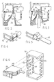
- the blades 33,34 may be replaced by a single contact blade 40, as shown in Figure 5 .
- the contact blade 40 is connected to the flat side 31 of the contact element by an elongated portion 29 which is folded in a U shape and provides the blade with a certain elasticity in the axial direction of the blade.
- a contact spring 55 which is similar or identical to the spring 14 ( Fig. 1 ), may be inserted in the saddle 29, as indicated by the arrow 56.
- the blades 33,34 may be replaced by two short tongues 41,42 which are suitably folded in order to grip permanently an end 43 of an electric cable 27, by means of crimping, as shown in Figure 4 .
- permanent fixing of the cable end may be performed by means of soldering.
- these walls have suitable undercuts (only one of which 44 is visible) which are arranged next to each other and form said opening.
- the contact spring 14 consists of a tongue of music steel folded in a U shape with a flattened and tapered end 45 which is inserted in the eyelet 32 of the contact element 13 and presses against the flat side 31.
- the opposite end 46 of the contact spring which is also tapered and folded externally in the form of an L, is inserted in the eyelet 32 and arranged in contact with the rim 47 of the eyelet opposite the flat side 31.
- Figure 2 shows the arrangement of the various parts in the insulating case with the lever 16 and the spring 14 in the rest position.
- Figure 3 shows the arrangement of the various parts when the lever 16 is operated with a small rotation in an anti-clockwise direction and exerts a thrusting force, with its wall 25, against the portion 49 of the contact spring.
- the end 45 of the contact spring is spaced apart from the flat side 31 of the contact element and it is possible to insert, through the opening 24 of the actuating lever, a cable end 50 which is arranged freely and without force between the flat side 31 of the contact element and the end 45 of the contact spring.
- the contact spring tends to assume again its rest position, firmly pressing the terminal 50 against the flat surface 31.
- the pressure exerted by the spring which is distributed along the whole extension of the end 45, ensures that there is a broad contact section such that the contact resistance is minimal.
- the structure of the lever with the point of application of the resistive force between the fulcrum and the point of application of the active force, ensures amplification of the active force such that operation performed to open the contact spring is easier.
- the device described may be used as a single-wire flying connector, but advantageously may be used as a component of a multi-pole connector.
- FIG. 6 The exploded perspective view of Figure 6 shows in schematic form a preferred embodiment of this type of connector.
- a case 51 made of insulating material has, formed internally, a plurality of seats, for example 6 seats (or also a single collective seat, as shown), inside each of which a connection device such as that already described may be inserted.
- a side surface of the case has, opposite each seat, a slit 52, open at a front end, for insertion of the blade or blades such as 33,34 or 40 ( Figs. 1 , 5 ) of the connection device.
- An engagement groove 53 is formed on the opposite side of each of the seats and has a dovetail cross-section inside which the engaging tooth 26 of the connection device is inserted.
- the engagement grooves terminate in a stop member 54 which defines the insertion depth of the connection devices inside the respective seats.
- This tooth prevents disengagement of the connection device from the seat, unless the tooth 30 is deliberately disengaged from the stop member 54.
- This type of connector which may be formed according to requirements, is particularly advantageous for connection to the conducting bars of a three-phase system with neutral and to a pair of bars for an auxiliary voltage. Generally, the user does not require connection to all the conducting bars, but only to some of these.
- connection devices even only two which are arranged in a suitable manner, depending on the connection required.
- the case 51 may be replaced by a simple support base-piece which may have two sides corresponding to the base and to the top of the case shown in Figure 6 .
- the base-piece has, formed inside it, the grooves 54 at a distance from each other such that the connection devices mounted on the base are in contact with each other.
Landscapes
- Details Of Connecting Devices For Male And Female Coupling (AREA)
- Coupling Device And Connection With Printed Circuit (AREA)
- Multi-Conductor Connections (AREA)
- Connections By Means Of Piercing Elements, Nuts, Or Screws (AREA)
Priority Applications (5)
| Application Number | Priority Date | Filing Date | Title |
|---|---|---|---|
| DE602008000975T DE602008000975D1 (de) | 2008-01-31 | 2008-01-31 | Elektrische Verbindungsvorrichtung mit Kontaktfeder, die von einem Hebel mit einer Einlassöffnung für das Ende eines elektrischen Kabels betrieben wird |
| ES08425054T ES2343096T3 (es) | 2008-01-31 | 2008-01-31 | Dispositivo de conexion electrico con resorte de contacto accionado para un brazo con una abertura de entrada para el extremo de un cable electrico. |
| AT08425054T ATE463863T1 (de) | 2008-01-31 | 2008-01-31 | Elektrische verbindungsvorrichtung mit kontaktfeder, die von einem hebel mit einer einlassöffnung für das ende eines elektrischen kabels betrieben wird |
| PT08425054T PT2096714E (pt) | 2008-01-31 | 2008-01-31 | Dispositivo de ligação eléctrica com mola de contacto comandada por uma alavanca que possui uma abertura de entrada para o terminal de um cabo eléctrico |
| EP08425054A EP2096714B1 (fr) | 2008-01-31 | 2008-01-31 | Dispositif de connexion électrique doté d'un ressort de contact actionné par un levier doté d'une ouverture d'entrée pour accueillir l'extrémité d'un câble électrique |
Applications Claiming Priority (1)
| Application Number | Priority Date | Filing Date | Title |
|---|---|---|---|
| EP08425054A EP2096714B1 (fr) | 2008-01-31 | 2008-01-31 | Dispositif de connexion électrique doté d'un ressort de contact actionné par un levier doté d'une ouverture d'entrée pour accueillir l'extrémité d'un câble électrique |
Publications (2)
| Publication Number | Publication Date |
|---|---|
| EP2096714A1 true EP2096714A1 (fr) | 2009-09-02 |
| EP2096714B1 EP2096714B1 (fr) | 2010-04-07 |
Family
ID=39512679
Family Applications (1)
| Application Number | Title | Priority Date | Filing Date |
|---|---|---|---|
| EP08425054A Not-in-force EP2096714B1 (fr) | 2008-01-31 | 2008-01-31 | Dispositif de connexion électrique doté d'un ressort de contact actionné par un levier doté d'une ouverture d'entrée pour accueillir l'extrémité d'un câble électrique |
Country Status (5)
| Country | Link |
|---|---|
| EP (1) | EP2096714B1 (fr) |
| AT (1) | ATE463863T1 (fr) |
| DE (1) | DE602008000975D1 (fr) |
| ES (1) | ES2343096T3 (fr) |
| PT (1) | PT2096714E (fr) |
Cited By (13)
| Publication number | Priority date | Publication date | Assignee | Title |
|---|---|---|---|---|
| DE102012005465B3 (de) * | 2012-03-20 | 2013-05-08 | Wieland Electric Gmbh | Federklemme |
| WO2014170273A1 (fr) * | 2013-04-15 | 2014-10-23 | Weidmüller Interface GmbH & Co. KG | Élément de serrage à force élastique doté d'un levier pivotant |
| KR20150116853A (ko) * | 2013-02-13 | 2015-10-16 | 바고 페어발퉁스게젤샤프트 엠베하 | 전기 전도체를 위한 스프링 클램프 접촉부 및 연결 단자 |
| DE202015102045U1 (de) * | 2015-04-24 | 2016-07-26 | Weidmüller Interface GmbH & Co. KG | Federkraftklemmelement mit Schwenkhebel |
| DE102015104625A1 (de) * | 2015-03-26 | 2016-09-29 | Phoenix Contact Gmbh & Co. Kg | Leiteranschlussklemme |
| CN108429042A (zh) * | 2018-03-20 | 2018-08-21 | 苏州惠华电子科技有限公司 | 一种紧凑型快速接线连接器 |
| WO2023154177A1 (fr) * | 2022-02-09 | 2023-08-17 | Leviton Manufacturing Co., Inc. | Bornes de fil et procédé d'utilisation |
| US11791573B2 (en) | 2021-04-15 | 2023-10-17 | Leviton Manufacturing Co., Inc. | Wire terminals and method of uses |
| DE202022105273U1 (de) * | 2022-09-19 | 2024-01-03 | WAGO Verwaltungsgesellschaft mit beschränkter Haftung | Kontaktstück, Kontakteinsatz, Steckverbinder, Blechzuschnitt und Verteilerblock |
| LU502539B1 (de) * | 2022-07-21 | 2024-01-22 | Phoenix Contact Gmbh & Co | Anschlussanordnung mit zumindest einer Anschlussklemme zum Anschließen einer elektrischen Leitung |
| LU502538B1 (de) * | 2022-07-21 | 2024-01-22 | Phoenix Contact Gmbh & Co | Anschlussklemme zum Anschließen einer elektrischen Leitung |
| LU502541B1 (de) * | 2022-07-21 | 2024-01-22 | Phoenix Contact Gmbh & Co | Anschlussanordnung mit einer Mehrzahl von Anschlussklemmen zum Anschließen elektrischer Leitungen |
| DE202024102475U1 (de) * | 2024-05-14 | 2025-08-18 | WAGO Verwaltungsgesellschaft mit beschränkter Haftung | Leiteranschlussklemme |
Families Citing this family (1)
| Publication number | Priority date | Publication date | Assignee | Title |
|---|---|---|---|---|
| DE102014119421B4 (de) * | 2014-12-22 | 2017-02-02 | Wago Verwaltungsgesellschaft Mbh | Verbindungsklemme und Verfahren zur Montage einer Verbindungsklemme |
Citations (6)
| Publication number | Priority date | Publication date | Assignee | Title |
|---|---|---|---|---|
| CA1022637A (fr) * | 1973-12-05 | 1977-12-13 | Sony Corporation | Cosse a elements de retenue rotatifs et resilients |
| EP1296413A1 (fr) | 2001-09-20 | 2003-03-26 | Entrelec SA | Dispositif de raccordement à ressort de connexion manoeuvré par une came |
| EP1605547A1 (fr) * | 2004-06-10 | 2005-12-14 | Simon, S.A. | Mécanisme de connection et de déconnexion rapide pour dispositifs électriques |
| EP1641079A1 (fr) * | 2004-09-27 | 2006-03-29 | Legrand | Appareil comportant un bloc de raccordement |
| EP1816706A1 (fr) * | 2006-02-02 | 2007-08-08 | Phoenix Contact GmbH & Co. KG | Borne de connexion électrique |
| DE102006010309A1 (de) | 2006-03-07 | 2007-09-13 | Phoenix Contact Gmbh & Co. Kg | Dosenklemme |
-
2008
- 2008-01-31 AT AT08425054T patent/ATE463863T1/de active
- 2008-01-31 ES ES08425054T patent/ES2343096T3/es active Active
- 2008-01-31 EP EP08425054A patent/EP2096714B1/fr not_active Not-in-force
- 2008-01-31 DE DE602008000975T patent/DE602008000975D1/de active Active
- 2008-01-31 PT PT08425054T patent/PT2096714E/pt unknown
Patent Citations (6)
| Publication number | Priority date | Publication date | Assignee | Title |
|---|---|---|---|---|
| CA1022637A (fr) * | 1973-12-05 | 1977-12-13 | Sony Corporation | Cosse a elements de retenue rotatifs et resilients |
| EP1296413A1 (fr) | 2001-09-20 | 2003-03-26 | Entrelec SA | Dispositif de raccordement à ressort de connexion manoeuvré par une came |
| EP1605547A1 (fr) * | 2004-06-10 | 2005-12-14 | Simon, S.A. | Mécanisme de connection et de déconnexion rapide pour dispositifs électriques |
| EP1641079A1 (fr) * | 2004-09-27 | 2006-03-29 | Legrand | Appareil comportant un bloc de raccordement |
| EP1816706A1 (fr) * | 2006-02-02 | 2007-08-08 | Phoenix Contact GmbH & Co. KG | Borne de connexion électrique |
| DE102006010309A1 (de) | 2006-03-07 | 2007-09-13 | Phoenix Contact Gmbh & Co. Kg | Dosenklemme |
Cited By (23)
| Publication number | Priority date | Publication date | Assignee | Title |
|---|---|---|---|---|
| DE102012005465B3 (de) * | 2012-03-20 | 2013-05-08 | Wieland Electric Gmbh | Federklemme |
| EP2642599A1 (fr) | 2012-03-20 | 2013-09-25 | Wieland Electric GmbH | Point de serrage de ressort |
| KR20150116853A (ko) * | 2013-02-13 | 2015-10-16 | 바고 페어발퉁스게젤샤프트 엠베하 | 전기 전도체를 위한 스프링 클램프 접촉부 및 연결 단자 |
| JP2016507147A (ja) * | 2013-02-13 | 2016-03-07 | ヴァーゴ・フェアヴァルトゥングスゲゼルシャフト・エムベーハー | ばね締付接点および電気導体用結合端子 |
| WO2014170273A1 (fr) * | 2013-04-15 | 2014-10-23 | Weidmüller Interface GmbH & Co. KG | Élément de serrage à force élastique doté d'un levier pivotant |
| CN105122550A (zh) * | 2013-04-15 | 2015-12-02 | 威德米勒界面有限公司及两合公司 | 具有枢轴转动杆的弹簧力夹紧元件 |
| JP2016519404A (ja) * | 2013-04-15 | 2016-06-30 | ヴァイトミュラー インターフェイス ゲゼルシャフト ミット ベシュレンクテル ハフツング ウント コンパニー コマンデイトゲゼルシャフト | ピボットレバーを備えたバネ力式締付け装置 |
| DE102015104625B4 (de) | 2015-03-26 | 2022-11-17 | Phoenix Contact Gmbh & Co. Kg | Leiteranschlussklemme |
| DE102015104625A1 (de) * | 2015-03-26 | 2016-09-29 | Phoenix Contact Gmbh & Co. Kg | Leiteranschlussklemme |
| DE202015102045U1 (de) * | 2015-04-24 | 2016-07-26 | Weidmüller Interface GmbH & Co. KG | Federkraftklemmelement mit Schwenkhebel |
| CN108429042B (zh) * | 2018-03-20 | 2024-10-11 | 苏州惠华电子科技有限公司 | 一种紧凑型快速接线连接器 |
| CN108429042A (zh) * | 2018-03-20 | 2018-08-21 | 苏州惠华电子科技有限公司 | 一种紧凑型快速接线连接器 |
| US11791573B2 (en) | 2021-04-15 | 2023-10-17 | Leviton Manufacturing Co., Inc. | Wire terminals and method of uses |
| US12244112B2 (en) | 2021-04-15 | 2025-03-04 | Leviton Manufacturing Co., Inc. | Wire terminals and method of uses |
| WO2023154177A1 (fr) * | 2022-02-09 | 2023-08-17 | Leviton Manufacturing Co., Inc. | Bornes de fil et procédé d'utilisation |
| LU502539B1 (de) * | 2022-07-21 | 2024-01-22 | Phoenix Contact Gmbh & Co | Anschlussanordnung mit zumindest einer Anschlussklemme zum Anschließen einer elektrischen Leitung |
| LU502541B1 (de) * | 2022-07-21 | 2024-01-22 | Phoenix Contact Gmbh & Co | Anschlussanordnung mit einer Mehrzahl von Anschlussklemmen zum Anschließen elektrischer Leitungen |
| WO2024017727A1 (fr) * | 2022-07-21 | 2024-01-25 | Phoenix Contact Gmbh & Co. Kg | Agencement de connexion comprenant au moins une borne de connexion pour connecter une ligne électrique |
| WO2024017993A1 (fr) * | 2022-07-21 | 2024-01-25 | Phoenix Contact Gmbh & Co. Kg | Borne de connexion pour connecter une ligne électrique |
| WO2024017994A1 (fr) * | 2022-07-21 | 2024-01-25 | Phoenix Contact Gmbh & Co. Kg | Ensemble de connexion ayant une pluralité de bornes de connexion pour connecter des lignes électriques |
| LU502538B1 (de) * | 2022-07-21 | 2024-01-22 | Phoenix Contact Gmbh & Co | Anschlussklemme zum Anschließen einer elektrischen Leitung |
| DE202022105273U1 (de) * | 2022-09-19 | 2024-01-03 | WAGO Verwaltungsgesellschaft mit beschränkter Haftung | Kontaktstück, Kontakteinsatz, Steckverbinder, Blechzuschnitt und Verteilerblock |
| DE202024102475U1 (de) * | 2024-05-14 | 2025-08-18 | WAGO Verwaltungsgesellschaft mit beschränkter Haftung | Leiteranschlussklemme |
Also Published As
| Publication number | Publication date |
|---|---|
| ES2343096T3 (es) | 2010-07-22 |
| ATE463863T1 (de) | 2010-04-15 |
| PT2096714E (pt) | 2010-05-21 |
| DE602008000975D1 (de) | 2010-05-20 |
| EP2096714B1 (fr) | 2010-04-07 |
Similar Documents
| Publication | Publication Date | Title |
|---|---|---|
| EP2096714B1 (fr) | Dispositif de connexion électrique doté d'un ressort de contact actionné par un levier doté d'une ouverture d'entrée pour accueillir l'extrémité d'un câble électrique | |
| KR101368118B1 (ko) | 전기 접속 단자용 작동 장치 | |
| EP3145035B1 (fr) | Agencement destiné à établir une connexion électrique entre un contact mâle et un conducteur de courant élevé | |
| CN107078414B (zh) | 接线端子和用于安装接线端子的方法 | |
| US4397514A (en) | Self-clamping electrical connectors and terminal blocks | |
| JP6665280B2 (ja) | 導体接続接点要素 | |
| JP6676297B2 (ja) | バネ接続部材と小型のアクチュエータとを備える電気的な接続デバイス、および複数の当該バネのコンタクトを備える多極プラグコネクタ | |
| CN109728450B (zh) | 导线连接夹和接触插入件 | |
| US10014596B2 (en) | Conductor terminal | |
| EP2947718B1 (fr) | Borne de connexion de serrage à ressort | |
| EP2483969B1 (fr) | Clip conducteur monobloc pour connecteur de fils à emboîtement | |
| EP1953872A2 (fr) | Douille électrique | |
| JP5491837B2 (ja) | 速結端子装置 | |
| KR100292230B1 (ko) | 전기도체용 연결단자 | |
| US20050266725A1 (en) | Clamping connector for flexible ribbon cables | |
| EP2323155A1 (fr) | Dispositif contacteur mobile de disjoncteur | |
| EP3075033B1 (fr) | Agencement pour un connecteur électrique | |
| US20220384967A1 (en) | Terminal | |
| EP2048741B1 (fr) | Terminal sans vis pour fils électriques | |
| CN110088982B (zh) | 配备有接触元件的电连接元件 | |
| JP5647027B2 (ja) | 電線接続用コネクタ | |
| JP5743213B2 (ja) | フラットケーブル用雌型端子 | |
| RU2416138C2 (ru) | Быстро разъединяемый контакт, выполненный с возможностью помещения в выводном щитке, в частности, для электронного устройства воспламенителя газа для электрических бытовых приборов | |
| US3180955A (en) | Fusible safety electrical attachment plug | |
| EP2051332B1 (fr) | Terminal de connexion à câblage rapide amélioré |
Legal Events
| Date | Code | Title | Description |
|---|---|---|---|
| PUAI | Public reference made under article 153(3) epc to a published international application that has entered the european phase |
Free format text: ORIGINAL CODE: 0009012 |
|
| GRAP | Despatch of communication of intention to grant a patent |
Free format text: ORIGINAL CODE: EPIDOSNIGR1 |
|
| 17P | Request for examination filed |
Effective date: 20080724 |
|
| AK | Designated contracting states |
Kind code of ref document: A1 Designated state(s): AT BE BG CH CY CZ DE DK EE ES FI FR GB GR HR HU IE IS IT LI LT LU LV MC MT NL NO PL PT RO SE SI SK TR |
|
| AX | Request for extension of the european patent |
Extension state: AL BA MK RS |
|
| GRAS | Grant fee paid |
Free format text: ORIGINAL CODE: EPIDOSNIGR3 |
|
| GRAA | (expected) grant |
Free format text: ORIGINAL CODE: 0009210 |
|
| AK | Designated contracting states |
Kind code of ref document: B1 Designated state(s): AT BE BG CH CY CZ DE DK EE ES FI FR GB GR HR HU IE IS IT LI LT LU LV MC MT NL NO PL PT RO SE SI SK TR |
|
| REG | Reference to a national code |
Ref country code: GB Ref legal event code: FG4D |
|
| REG | Reference to a national code |
Ref country code: CH Ref legal event code: EP |
|
| AKX | Designation fees paid |
Designated state(s): AT BE BG CH CY CZ DE DK EE ES FI FR GB GR HR HU IE IS IT LI LT LU LV MC MT NL NO PL PT RO SE SI SK TR |
|
| REG | Reference to a national code |
Ref country code: IE Ref legal event code: FG4D |
|
| REF | Corresponds to: |
Ref document number: 602008000975 Country of ref document: DE Date of ref document: 20100520 Kind code of ref document: P |
|
| REG | Reference to a national code |
Ref country code: PT Ref legal event code: SC4A Free format text: AVAILABILITY OF NATIONAL TRANSLATION Effective date: 20100512 |
|
| REG | Reference to a national code |
Ref country code: ES Ref legal event code: FG2A Ref document number: 2343096 Country of ref document: ES Kind code of ref document: T3 |
|
| REG | Reference to a national code |
Ref country code: NL Ref legal event code: VDEP Effective date: 20100407 |
|
| PG25 | Lapsed in a contracting state [announced via postgrant information from national office to epo] |
Ref country code: SI Free format text: LAPSE BECAUSE OF FAILURE TO SUBMIT A TRANSLATION OF THE DESCRIPTION OR TO PAY THE FEE WITHIN THE PRESCRIBED TIME-LIMIT Effective date: 20100407 |
|
| LTIE | Lt: invalidation of european patent or patent extension |
Effective date: 20100407 |
|
| PG25 | Lapsed in a contracting state [announced via postgrant information from national office to epo] |
Ref country code: SE Free format text: LAPSE BECAUSE OF FAILURE TO SUBMIT A TRANSLATION OF THE DESCRIPTION OR TO PAY THE FEE WITHIN THE PRESCRIBED TIME-LIMIT Effective date: 20100407 Ref country code: NO Free format text: LAPSE BECAUSE OF FAILURE TO SUBMIT A TRANSLATION OF THE DESCRIPTION OR TO PAY THE FEE WITHIN THE PRESCRIBED TIME-LIMIT Effective date: 20100707 Ref country code: NL Free format text: LAPSE BECAUSE OF FAILURE TO SUBMIT A TRANSLATION OF THE DESCRIPTION OR TO PAY THE FEE WITHIN THE PRESCRIBED TIME-LIMIT Effective date: 20100407 Ref country code: LT Free format text: LAPSE BECAUSE OF FAILURE TO SUBMIT A TRANSLATION OF THE DESCRIPTION OR TO PAY THE FEE WITHIN THE PRESCRIBED TIME-LIMIT Effective date: 20100407 |
|
| PG25 | Lapsed in a contracting state [announced via postgrant information from national office to epo] |
Ref country code: IS Free format text: LAPSE BECAUSE OF FAILURE TO SUBMIT A TRANSLATION OF THE DESCRIPTION OR TO PAY THE FEE WITHIN THE PRESCRIBED TIME-LIMIT Effective date: 20100807 Ref country code: HR Free format text: LAPSE BECAUSE OF FAILURE TO SUBMIT A TRANSLATION OF THE DESCRIPTION OR TO PAY THE FEE WITHIN THE PRESCRIBED TIME-LIMIT Effective date: 20100407 Ref country code: FI Free format text: LAPSE BECAUSE OF FAILURE TO SUBMIT A TRANSLATION OF THE DESCRIPTION OR TO PAY THE FEE WITHIN THE PRESCRIBED TIME-LIMIT Effective date: 20100407 Ref country code: LV Free format text: LAPSE BECAUSE OF FAILURE TO SUBMIT A TRANSLATION OF THE DESCRIPTION OR TO PAY THE FEE WITHIN THE PRESCRIBED TIME-LIMIT Effective date: 20100407 |
|
| PG25 | Lapsed in a contracting state [announced via postgrant information from national office to epo] |
Ref country code: CY Free format text: LAPSE BECAUSE OF FAILURE TO SUBMIT A TRANSLATION OF THE DESCRIPTION OR TO PAY THE FEE WITHIN THE PRESCRIBED TIME-LIMIT Effective date: 20100616 Ref country code: PL Free format text: LAPSE BECAUSE OF FAILURE TO SUBMIT A TRANSLATION OF THE DESCRIPTION OR TO PAY THE FEE WITHIN THE PRESCRIBED TIME-LIMIT Effective date: 20100407 |
|
| PG25 | Lapsed in a contracting state [announced via postgrant information from national office to epo] |
Ref country code: EE Free format text: LAPSE BECAUSE OF FAILURE TO SUBMIT A TRANSLATION OF THE DESCRIPTION OR TO PAY THE FEE WITHIN THE PRESCRIBED TIME-LIMIT Effective date: 20100407 Ref country code: DK Free format text: LAPSE BECAUSE OF FAILURE TO SUBMIT A TRANSLATION OF THE DESCRIPTION OR TO PAY THE FEE WITHIN THE PRESCRIBED TIME-LIMIT Effective date: 20100407 |
|
| PLBE | No opposition filed within time limit |
Free format text: ORIGINAL CODE: 0009261 |
|
| STAA | Information on the status of an ep patent application or granted ep patent |
Free format text: STATUS: NO OPPOSITION FILED WITHIN TIME LIMIT |
|
| PG25 | Lapsed in a contracting state [announced via postgrant information from national office to epo] |
Ref country code: CZ Free format text: LAPSE BECAUSE OF FAILURE TO SUBMIT A TRANSLATION OF THE DESCRIPTION OR TO PAY THE FEE WITHIN THE PRESCRIBED TIME-LIMIT Effective date: 20100407 Ref country code: RO Free format text: LAPSE BECAUSE OF FAILURE TO SUBMIT A TRANSLATION OF THE DESCRIPTION OR TO PAY THE FEE WITHIN THE PRESCRIBED TIME-LIMIT Effective date: 20100407 Ref country code: SK Free format text: LAPSE BECAUSE OF FAILURE TO SUBMIT A TRANSLATION OF THE DESCRIPTION OR TO PAY THE FEE WITHIN THE PRESCRIBED TIME-LIMIT Effective date: 20100407 |
|
| 26N | No opposition filed |
Effective date: 20110110 |
|
| PG25 | Lapsed in a contracting state [announced via postgrant information from national office to epo] |
Ref country code: GR Free format text: LAPSE BECAUSE OF FAILURE TO SUBMIT A TRANSLATION OF THE DESCRIPTION OR TO PAY THE FEE WITHIN THE PRESCRIBED TIME-LIMIT Effective date: 20100708 |
|
| PG25 | Lapsed in a contracting state [announced via postgrant information from national office to epo] |
Ref country code: MC Free format text: LAPSE BECAUSE OF NON-PAYMENT OF DUE FEES Effective date: 20110131 |
|
| REG | Reference to a national code |
Ref country code: IE Ref legal event code: MM4A |
|
| PG25 | Lapsed in a contracting state [announced via postgrant information from national office to epo] |
Ref country code: MT Free format text: LAPSE BECAUSE OF FAILURE TO SUBMIT A TRANSLATION OF THE DESCRIPTION OR TO PAY THE FEE WITHIN THE PRESCRIBED TIME-LIMIT Effective date: 20100407 |
|
| PG25 | Lapsed in a contracting state [announced via postgrant information from national office to epo] |
Ref country code: IE Free format text: LAPSE BECAUSE OF NON-PAYMENT OF DUE FEES Effective date: 20110131 |
|
| REG | Reference to a national code |
Ref country code: CH Ref legal event code: PL |
|
| PG25 | Lapsed in a contracting state [announced via postgrant information from national office to epo] |
Ref country code: CH Free format text: LAPSE BECAUSE OF NON-PAYMENT OF DUE FEES Effective date: 20120131 Ref country code: LI Free format text: LAPSE BECAUSE OF NON-PAYMENT OF DUE FEES Effective date: 20120131 |
|
| PG25 | Lapsed in a contracting state [announced via postgrant information from national office to epo] |
Ref country code: LU Free format text: LAPSE BECAUSE OF NON-PAYMENT OF DUE FEES Effective date: 20110131 |
|
| PG25 | Lapsed in a contracting state [announced via postgrant information from national office to epo] |
Ref country code: TR Free format text: LAPSE BECAUSE OF FAILURE TO SUBMIT A TRANSLATION OF THE DESCRIPTION OR TO PAY THE FEE WITHIN THE PRESCRIBED TIME-LIMIT Effective date: 20100407 Ref country code: BG Free format text: LAPSE BECAUSE OF FAILURE TO SUBMIT A TRANSLATION OF THE DESCRIPTION OR TO PAY THE FEE WITHIN THE PRESCRIBED TIME-LIMIT Effective date: 20100707 |
|
| PG25 | Lapsed in a contracting state [announced via postgrant information from national office to epo] |
Ref country code: HU Free format text: LAPSE BECAUSE OF FAILURE TO SUBMIT A TRANSLATION OF THE DESCRIPTION OR TO PAY THE FEE WITHIN THE PRESCRIBED TIME-LIMIT Effective date: 20100407 |
|
| REG | Reference to a national code |
Ref country code: FR Ref legal event code: PLFP Year of fee payment: 8 |
|
| PGFP | Annual fee paid to national office [announced via postgrant information from national office to epo] |
Ref country code: GB Payment date: 20141219 Year of fee payment: 8 |
|
| PGFP | Annual fee paid to national office [announced via postgrant information from national office to epo] |
Ref country code: IT Payment date: 20141222 Year of fee payment: 8 |
|
| PGFP | Annual fee paid to national office [announced via postgrant information from national office to epo] |
Ref country code: DE Payment date: 20141218 Year of fee payment: 8 Ref country code: ES Payment date: 20150119 Year of fee payment: 8 Ref country code: PT Payment date: 20150106 Year of fee payment: 8 |
|
| PGFP | Annual fee paid to national office [announced via postgrant information from national office to epo] |
Ref country code: AT Payment date: 20141219 Year of fee payment: 8 Ref country code: FR Payment date: 20150121 Year of fee payment: 8 |
|
| PGFP | Annual fee paid to national office [announced via postgrant information from national office to epo] |
Ref country code: BE Payment date: 20141217 Year of fee payment: 8 |
|
| PG25 | Lapsed in a contracting state [announced via postgrant information from national office to epo] |
Ref country code: BE Free format text: LAPSE BECAUSE OF NON-PAYMENT OF DUE FEES Effective date: 20160131 |
|
| REG | Reference to a national code |
Ref country code: DE Ref legal event code: R119 Ref document number: 602008000975 Country of ref document: DE |
|
| REG | Reference to a national code |
Ref country code: AT Ref legal event code: MM01 Ref document number: 463863 Country of ref document: AT Kind code of ref document: T Effective date: 20160131 |
|
| GBPC | Gb: european patent ceased through non-payment of renewal fee |
Effective date: 20160131 |
|
| REG | Reference to a national code |
Ref country code: FR Ref legal event code: ST Effective date: 20160930 |
|
| PG25 | Lapsed in a contracting state [announced via postgrant information from national office to epo] |
Ref country code: DE Free format text: LAPSE BECAUSE OF NON-PAYMENT OF DUE FEES Effective date: 20160802 Ref country code: GB Free format text: LAPSE BECAUSE OF NON-PAYMENT OF DUE FEES Effective date: 20160131 |
|
| PG25 | Lapsed in a contracting state [announced via postgrant information from national office to epo] |
Ref country code: FR Free format text: LAPSE BECAUSE OF NON-PAYMENT OF DUE FEES Effective date: 20160201 Ref country code: PT Free format text: LAPSE BECAUSE OF NON-PAYMENT OF DUE FEES Effective date: 20160801 Ref country code: AT Free format text: LAPSE BECAUSE OF NON-PAYMENT OF DUE FEES Effective date: 20160131 |
|
| PG25 | Lapsed in a contracting state [announced via postgrant information from national office to epo] |
Ref country code: IT Free format text: LAPSE BECAUSE OF NON-PAYMENT OF DUE FEES Effective date: 20160131 |
|
| PG25 | Lapsed in a contracting state [announced via postgrant information from national office to epo] |
Ref country code: ES Free format text: LAPSE BECAUSE OF NON-PAYMENT OF DUE FEES Effective date: 20160131 |
|
| REG | Reference to a national code |
Ref country code: ES Ref legal event code: FD2A Effective date: 20181207 |
|
| PG25 | Lapsed in a contracting state [announced via postgrant information from national office to epo] |
Ref country code: ES Free format text: LAPSE BECAUSE OF NON-PAYMENT OF DUE FEES Effective date: 20160201 |