EP2096776B1 - Vorrichtung und Verfahren zur Schätzung der Rauschleistung - Google Patents
Vorrichtung und Verfahren zur Schätzung der Rauschleistung Download PDFInfo
- Publication number
- EP2096776B1 EP2096776B1 EP09001097.6A EP09001097A EP2096776B1 EP 2096776 B1 EP2096776 B1 EP 2096776B1 EP 09001097 A EP09001097 A EP 09001097A EP 2096776 B1 EP2096776 B1 EP 2096776B1
- Authority
- EP
- European Patent Office
- Prior art keywords
- noise power
- received pilot
- pilot signal
- sampling
- signal
- Prior art date
- Legal status (The legal status is an assumption and is not a legal conclusion. Google has not performed a legal analysis and makes no representation as to the accuracy of the status listed.)
- Not-in-force
Links
- 238000000034 method Methods 0.000 title claims description 14
- 238000005070 sampling Methods 0.000 claims description 35
- 230000014509 gene expression Effects 0.000 claims description 14
- 238000012935 Averaging Methods 0.000 claims description 5
- 238000004891 communication Methods 0.000 description 7
- 125000004122 cyclic group Chemical group 0.000 description 6
- 238000006243 chemical reaction Methods 0.000 description 4
- 230000005540 biological transmission Effects 0.000 description 3
- 230000000875 corresponding effect Effects 0.000 description 3
- 238000012545 processing Methods 0.000 description 3
- 230000003044 adaptive effect Effects 0.000 description 2
- 238000010586 diagram Methods 0.000 description 2
- 238000005516 engineering process Methods 0.000 description 2
- 238000005562 fading Methods 0.000 description 2
- 230000010363 phase shift Effects 0.000 description 2
- 230000002596 correlated effect Effects 0.000 description 1
- 230000001419 dependent effect Effects 0.000 description 1
- 239000000284 extract Substances 0.000 description 1
- 230000036039 immunity Effects 0.000 description 1
- 238000005259 measurement Methods 0.000 description 1
- 230000008054 signal transmission Effects 0.000 description 1
- 238000012546 transfer Methods 0.000 description 1
- 238000011144 upstream manufacturing Methods 0.000 description 1
Images


Classifications
-
- H—ELECTRICITY
- H04—ELECTRIC COMMUNICATION TECHNIQUE
- H04B—TRANSMISSION
- H04B17/00—Monitoring; Testing
- H04B17/30—Monitoring; Testing of propagation channels
- H04B17/309—Measuring or estimating channel quality parameters
- H04B17/345—Interference values
-
- H—ELECTRICITY
- H04—ELECTRIC COMMUNICATION TECHNIQUE
- H04L—TRANSMISSION OF DIGITAL INFORMATION, e.g. TELEGRAPHIC COMMUNICATION
- H04L27/00—Modulated-carrier systems
- H04L27/26—Systems using multi-frequency codes
- H04L27/2601—Multicarrier modulation systems
- H04L27/2647—Arrangements specific to the receiver only
Definitions
- the present invention relates to noise power estimation apparatuses and methods, and more particularly, to a noise power estimation apparatus and method for estimating noise power and noise interference used for signal quality measurement in radio receivers in various radio communication systems such as orthogonal frequency division multiplexing access (OFDMA) communication systems.
- OFDMA orthogonal frequency division multiplexing access
- a base station adds a power control signal to a forward link (from the base station to a mobile terminal) signal and sends them to the mobile terminal to control the power of the mobile terminal in order to control the power of the reverse link (from the mobile terminal to the base station).
- a signal to interference power ratio SIR, a desired signal to interference ratio in power
- the power level used for transmission from the mobile terminal to the base station corresponds to the lowest minimum receiving quality at the base station. This is for system stability and capacity improvement. If an excessive power level is used, it may cause extra interference or excessive traffic in the entire system, reducing the efficiency of the system.
- the interference power I is sufficiently higher than the signal power S, the variance of a receiving signal is obtained to easily calculate the noise power (for example, see PCT International Patent Application Publication in Japanese NO. 2004-533783 ).
- noise in a low S/N region which is not suited to adaptive modulation, a signal itself may have an error to greatly shift the receiving signal from the expected area, reducing noise estimation precision.
- Noise in a low S/N region may be able to be estimated when the noise estimation method used in the CDMA system, where the variance of the receiving signal is statistically obtained, is applied to the OFDMA system.
- this method cannot be applied to a high S/N region because there is almost no variance of noise.
- frequency selectivity is provided for an OFDMA system where communication is made in a wide bandwidth, it cannot be determined whether the difference from a desired signal indicates a noise component or is caused by the influence of fading, making it difficult to estimate noise.
- US 2007/0243837 A1 discloses a method of evaluating the transmitter performance according to which average channel estimates for subcarriers are used with the known pilot symbols to determine noise or error for each subcarrier.
- a particular pilot signal can be estimated by the sampling theorem by using other sampled pilot signals.
- the pilot component of a pilot signal (r 0 ) received at a particular time correlates with the pilot component of a pilot signal (r 0 ') obtained when the pilot signal (r 0 ') is estimated by the sampling theorem, and the difference between their power components is zero. Because noise components added to the individual signals have no correlation, the difference between the power of the received pilot signal and the power of the estimated pilot signal is statistically calculated to obtain the variance of noise, thereby allowing the noise power to be estimated.
- sampling theorem means that, to correctly reproduce the frequency components included in a continuous signal as sampling data, the sampling frequency should be twice or more of the maximum frequency of the continuous signal.
- a signal g(t) having the maximum frequency f 0 can be expressed by the following Expression 1.
- Receiver that includes a noise power estimation section (apparatus)
- Fig. 1 is a function block diagram of a receiver (demodulator) that includes a noise power estimation section (apparatus) according to an embodiment of the present invention.
- the receiver can be used especially in OFDMA systems.
- the receiver includes an antenna 010, an analog-to-digital (A/D) converter 011, a guard interval remover 012, a fast Fourier transform (FFT) processor 013, a demapping processor 014 to a complex plane, a parallel-to-serial (P/S) processor 015, a received signal power estimation section 016, a signal-to-interference power ratio (SIR) estimating section 017, a channel quality indicator (CQI) generator 018, and a noise power estimation section 020.
- A/D analog-to-digital
- FFT fast Fourier transform
- P/S parallel-to-serial
- SIR signal-to-interference power ratio
- CQI channel quality indicator
- the antenna 010 receives a signal sent from a transmitter.
- the antenna 010 can also be used for signal transmission.
- the A/D converter 011 converts the signal received by the antenna 010, which is analog, to a digital signal.
- the guard interval remover 012 removes a guard interval given by the transmitter.
- a cyclic prefix is, for example, used as a guard interval.
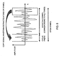
- Fig. 6 shows the cyclic prefix used as a guard interval.
- the cyclic prefix is a copy added to the top of an OFDM symbol, of a part of the signal waveform extracted at an end portion of the OFDM symbol.
- a portion indicated as an effective symbol is the original OFDM symbol (before the cyclic prefix was added), and this portion is necessary for demodulation.
- This portion is converted (divided into subcarriers) to the frequency domain by fast Fourier transform (by the FFT processor 013 in the present embodiment). Only one period of the original OFDM symbol (any portion having the effective symbol length, of the OFDM symbol) needs to be obtained. Therefore, the cyclic prefix is a redundant signal portion and can be discarded by the receiver.
- the FFT processor 013 applies fast Fourier transform to the input signal to convert (divide) it to signals in the frequency domain.
- the demapping processor 014 maps the signals in the frequency domain output from the FFT processor 013 onto the complex plane for each subcarrier and also extracts a pilot signal inserted for each subcarrier.
- the P/S converter 015 converts a parallel signal to a serial signal.
- the P/S converter 015 converts multiple-value signals (such as those in QPSK, QAM, or the like) expressed in the complex plane by demapping in the demapping processor 014 to a binary data signal.
- the received signal power estimation section 016 estimates the power of the received signal by using the pilot signal received from the demapping processor 014 as a reference.
- the power of the received signal depends on the magnitude of the pilot signal.
- the pilot signal can be multiplied by a given value that indicates the power of the received signal to estimate the power of the received signal. This given value may be determined in advance, or may be specified in the received signal and read and used. Therefore, the power of the pilot signal can be measured to estimate the power of the received signal.
- the noise power estimation section 020 estimates noise power from the pilot signal received from the demapping processor 014. Noise power estimation according to the present embodiment, performed by the noise power estimation section 020 will be described in detail later in "3. Noise power estimation".
- the SIR estimation section 017 estimates the SIR of the signal from the power of the received signal, estimated by the received signal power estimation section 016 and the noise power estimated by the noise power estimation section 020.
- the CQI generator 018 selects an index corresponding to the receiving quality according to the SIR received from the SIR estimation section 017. Depending on the transfer condition of the transmission path, this index is fed back to the transmitter to change the modulation method and the transmission rate.
- Fig. 3 shows the structure of the noise power estimation section 020.
- Fig. 2 shows boundaries in the complex plane, serving as determination references in the P/S conversion, a received pilot signal, and replica signals generated from the pilot signal.
- Fig. 4 shows the complex amplitude of the received pilot signal.
- the noise power estimation section 020 includes a sampling processor 021, a pilot signal estimation section 022, and a noise power calculator 023.
- the sampling processor 021 samples the pilot signal received from the demapping processor 014 at a constant sampling interval in the frequency domain.
- the sampling interval is shorter than the maximum delay spread of the signal because the condition under which the sampling theorem used by the pilot signal estimation section 022 is satisfied needs to be met.
- the pilot signal on the complex plane shown in Fig. 2 , is sampled and shown in complex amplitude as in Fig. 4 .
- the estimated pilot signal r 0 ' can be expressed by the following Expression 3.
- the range from - ⁇ to ⁇ can be set to a given finite value range determined in advance from -M to M as shown in the following Expression 3'.
- M indicates a predetermined integer.
- the number of samples can be reduced by using a window function when the sampling theorem is used.
- Any window function can be used.
- I 0 indicates the first type zeroth-order conversion Bessel function and N depends on the number of samples.
- the noise power calculator 023 calculates the statistical average of the difference between the actually received pilot signal r 0 and the estimated received pilot signal r 0 ' estimate by the pilot signal estimation section 022 to estimate the noise power.
- Fig. 5 shows the received pilot signal and the estimated pilot signal in an amplitude plane.
- the received pilot signal r 0 and the estimated pilot signal r 0 ' have correlated pilot components and noise components having no correlation are added to the signals. Therefore, a difference in complex amplitude occurs as shown in Fig. 5 .
- the number of sampling times in time can be set, for example, to 100 (time t 1 to t 100 for r 0 and r 0 ') or to 100 or more. This number can be specified appropriately.
- the noise power calculator 023 can calculate the resultant statistical value of Expression 7 and divide the value by 2 to obtain the variance ⁇ 2 as the noise power. In other words, the noise power calculator 023 can calculate
- the noise power calculator 023 can divide the average of the obtained
- 2 for each time is provided inside or outside the noise power calculator 023; the noise power calculator 023 calculates
- the noise power calculator 023 can shift and read the calculated values for the preceding predetermined number of sampling times (for example, 100 for t 2 to t 101 ), stored in the table, to execute the statistical averaging process of the difference in the same way.
- the present embodiment is just an embodiment of the present invention.
- the present invention is not limited to the present embodiment.
- the antenna 010 used for receiving a signal has just one antenna.
- the present invention can also be applied to a case where a plurality of antennas, such as multi-input-multi-output (MIMO) antennas, is employed.
- MIMO multi-input-multi-output
- the information about SIR estimated by the SIR estimation section 017 is sent only to the CQI generator 018. This information can be output to another apparatus for another process.
- a minimum mean squared error (MMSE) estimation section used for MIMO antennas or the like is used as the other apparatus to apply to a plurality of antennas, or a log likelihood ratio (LLR) calculator for a bit sequence is used as the other apparatus to calculate the LLR.
- MMSE minimum mean squared error
- LLR log likelihood ratio
- the present invention can be implemented by either hardware or software.
Landscapes
- Engineering & Computer Science (AREA)
- Quality & Reliability (AREA)
- Physics & Mathematics (AREA)
- Electromagnetism (AREA)
- Computer Networks & Wireless Communication (AREA)
- Signal Processing (AREA)
- Monitoring And Testing Of Transmission In General (AREA)
- Mobile Radio Communication Systems (AREA)
Claims (5)
- Vorrichtung zur Schätzung der Rauschleistung, die aufweist:einen Abtast-Prozessor (021) zum Abtasten eines Pilotsignals in einer komplexen Ebene bei einem konstanten Abtastintervall in einem Frequenzbereich und zur Ausgabe mehrerer empfangener Pilot-Abtastwerte rm , wobei m eine ganze Zahl bezeichnet,einen Pilotsignal-Schätzabschnitt (022) zum Schätzen eines empfangenen Pilot-Abtastwertes r0 der mehreren empfangenen Pilot-Abtastwerte, der eine bestimmte Frequenz aufweist, unter Anwendung des Abtasttheorems durch Verwendung von anderen empfangenen Pilot-Abtastwerten der mehreren empfangenen Pilot-Abtastwerte rm, mit m ≠ 0, die andere Frequenzen aufweisen, zum Erhalt eines geschätzten empfangenen Pilot-Abtastwertes r0'
undeine Rauschleistungs-Recheneinrichtung (023) zum Berechnen einer Differenz zwischen dem einen empfangenen Pilot-Abtastwert r0 der empfangenen Pilot-Abtastwerte und dem geschätzten empfangenen Pilot-Abtastwert ro' und zum Anwenden einer statistischen Mittelung auf diese Differenz innerhalb einer zuvor bestimmten Zeitdauer unter Erhalt einer Varianz σ2 als Rauschleistung durch Verwendung des nachstehenden Ausdrucks:
worin <> einen erwarteten Wert bezeichnet. - Vorrichtung zur Schätzung der Rauschleistung nach Anspruch 1,
bei welcher der Pilotsignal-Schätzabschnitt so ausgebildet ist, dass er den nachstehenden Ausdruck als Abtasttheorem verwendet, um den geschätzten empfangenen Pilot-Abtastwert r0' zu erhalten:
worin m in einen vorgegebenen bestimmten Bereich fällt. - Vorrichtung zur Schätzung der Rauschleistung nach Anspruch 1,
bei welcher der Pilotsignal-Schätzabschnitt so ausgebildet ist, dass er eine beliebige Fensterfunktion verwendet, um die Anzahl der Pilot-Abtastwerte, die für das Abtasttheorem erforderlich sind, zu verringern. - Vorrichtung zur Schätzung der Rauschleistung nach Anspruch 1,
bei welcher der Pilotsignal-Schätzabschnitt so ausgebildet ist, dass er den nachstehenden Ausdruck als Abtasttheorem verwendet, um den geschätzten empfangenen Pilot-Abtastwert r0' zu erhalten:
worin M eine vorgegebene ganze Zahl ist. - Verfahren zur Schätzung der Rauschleistung, das folgende Schritte umfasst:Abtasten eines Pilotsignals in einer komplexen Ebene bei einem konstanten Abtastintervall in einem Frequenzbereich zur Ausgabe mehrerer empfangener Pilot-Abtastwerte rm, wobei m eine ganze Zahl bezeichnet,Schätzen eines empfangenen Pilot-Abtastwertes r0 der mehreren empfangenen Pilot-Abtastwerte, der eine bestimmte Frequenz aufweist, durch Verwendung von anderen empfangenen Pilot-Abtastwerten der mehreren empfangenen Pilot-Abtastwerte rm, mit m ≠ 0, die andere Frequenzen aufweisen, zum Erhalt eines geschätzten empfangenen Pilot-Abtastwertes r0' durch Anwendung des Abtasttheorems,Berechnen einer Differenz zwischen dem einen empfangenen Pilot-Abtastwert r0 der mehreren empfangenen Pilot-Abtastwerte und dem geschätzten empfangenen Pilot-Abtastwert r0'
undAnwenden einer statistischen Mittelung auf diese Differenz innerhalb einer zuvor bestimmten Zeitdauer unter Erhalt einer Varianz σ2 als Rauschleistung durch Verwendung der folgenden Ausdrucks:
worin < > einen erwarteten Wert bezeichnet.
Applications Claiming Priority (1)
| Application Number | Priority Date | Filing Date | Title |
|---|---|---|---|
| JP2008045453A JP4875642B2 (ja) | 2008-02-27 | 2008-02-27 | 雑音電力推定装置及び方法 |
Publications (3)
| Publication Number | Publication Date |
|---|---|
| EP2096776A2 EP2096776A2 (de) | 2009-09-02 |
| EP2096776A3 EP2096776A3 (de) | 2012-02-15 |
| EP2096776B1 true EP2096776B1 (de) | 2013-08-14 |
Family
ID=40718736
Family Applications (1)
| Application Number | Title | Priority Date | Filing Date |
|---|---|---|---|
| EP09001097.6A Not-in-force EP2096776B1 (de) | 2008-02-27 | 2009-01-27 | Vorrichtung und Verfahren zur Schätzung der Rauschleistung |
Country Status (4)
| Country | Link |
|---|---|
| US (1) | US7916660B2 (de) |
| EP (1) | EP2096776B1 (de) |
| JP (1) | JP4875642B2 (de) |
| CN (1) | CN101521548B (de) |
Families Citing this family (7)
| Publication number | Priority date | Publication date | Assignee | Title |
|---|---|---|---|---|
| US8742749B2 (en) * | 2011-05-26 | 2014-06-03 | Tektronix, Inc. | Test and measurement instrument including asynchronous time-interleaved digitizer using harmonic mixing |
| US9226183B2 (en) * | 2013-06-03 | 2015-12-29 | Telefonaktiebolaget L M Ericsson (Publ) | Reference signal measurement |
| RU2577187C1 (ru) * | 2015-03-16 | 2016-03-10 | Александр Иосифович Иванов | Способ шифрования/дешифрования аналоговых сигналов, передаваемых по каналам связи |
| JP6586762B2 (ja) | 2015-04-07 | 2019-10-09 | ソニー株式会社 | 受信装置、送信装置、受信方法、送信方法及びプログラム |
| JP6571605B2 (ja) * | 2016-07-27 | 2019-09-04 | 日本電信電話株式会社 | 無線受信方法および無線受信装置 |
| CN111884956B (zh) * | 2020-06-29 | 2022-06-03 | 烽火通信科技股份有限公司 | 一种基于导频信号的snr估计方法及装置 |
| CN118944750B (zh) * | 2024-07-12 | 2025-06-06 | 集益威半导体(上海)有限公司 | 光信噪比的估计方法 |
Family Cites Families (10)
| Publication number | Priority date | Publication date | Assignee | Title |
|---|---|---|---|---|
| US6690311B2 (en) * | 1998-11-20 | 2004-02-10 | Telefonaktiebolaget Lm Ericsson (Publ) | Adaptively calibrating analog-to-digital conversion with correction table indexing |
| US7023938B1 (en) * | 1999-04-08 | 2006-04-04 | Nec Usa, Inc. | Receiver for discrete multitone modulated signals having window function |
| US7228146B2 (en) | 2001-06-26 | 2007-06-05 | Nxp B.V. | Estimating Eb/Nt in a CDMA system using power control bits |
| JP4369294B2 (ja) | 2004-05-13 | 2009-11-18 | 株式会社エヌ・ティ・ティ・ドコモ | 雑音電力推定装置、雑音電力推定方法及び信号検出装置 |
| KR100635534B1 (ko) * | 2004-06-28 | 2006-10-17 | 전자부품연구원 | 고속 이동 환경을 위한 하이브리드 채널 추정 방법 및시스템 |
| US7672383B2 (en) * | 2004-09-17 | 2010-03-02 | Qualcomm Incorporated | Noise variance estimation in wireless communications for diversity combining and log-likelihood scaling |
| US9002299B2 (en) * | 2004-10-01 | 2015-04-07 | Cisco Technology, Inc. | Multiple antenna processing on transmit for wireless local area networks |
| JP3724501B1 (ja) * | 2004-11-30 | 2005-12-07 | 三菱電機株式会社 | 復調装置、ダイバーシチ受信装置および復調方法 |
| WO2006098301A1 (ja) * | 2005-03-14 | 2006-09-21 | Sharp Kabushiki Kaisha | マルチキャリア信号受信機及びマルチキャリア信号受信方法 |
| US7734303B2 (en) * | 2006-04-12 | 2010-06-08 | Qualcomm Incorporated | Pilot modulation error ratio for evaluation of transmitter performance |
-
2008
- 2008-02-27 JP JP2008045453A patent/JP4875642B2/ja not_active Expired - Fee Related
-
2009
- 2009-01-23 CN CN2009100039142A patent/CN101521548B/zh not_active Expired - Fee Related
- 2009-01-27 EP EP09001097.6A patent/EP2096776B1/de not_active Not-in-force
- 2009-01-27 US US12/360,355 patent/US7916660B2/en not_active Expired - Fee Related
Also Published As
| Publication number | Publication date |
|---|---|
| EP2096776A3 (de) | 2012-02-15 |
| EP2096776A2 (de) | 2009-09-02 |
| CN101521548B (zh) | 2013-07-10 |
| US7916660B2 (en) | 2011-03-29 |
| JP2009206682A (ja) | 2009-09-10 |
| US20090213743A1 (en) | 2009-08-27 |
| CN101521548A (zh) | 2009-09-02 |
| JP4875642B2 (ja) | 2012-02-15 |
Similar Documents
| Publication | Publication Date | Title |
|---|---|---|
| Zhao et al. | A novel channel estimation method for OFDM mobile communication systems based on pilot signals and transform-domain processing | |
| EP1555761B1 (de) | Gerät und Verfahren zur Schätzung von Interferenzen und Rauschen in einem Nachrichtensystem | |
| US8744020B2 (en) | Frequency offset estimation | |
| US8064328B2 (en) | Channel estimation device | |
| RU2406238C2 (ru) | Оценивание шума для беспроводной связи | |
| EP2096776B1 (de) | Vorrichtung und Verfahren zur Schätzung der Rauschleistung | |
| JP4472771B2 (ja) | マルチキャリア信号を受信するための受信装置 | |
| KR100625686B1 (ko) | 효율적인 cnir 측정이 가능한 이동 단말 장치 및 그장치에서의 cnir 측정 방법 | |
| US20050286406A1 (en) | Hybrid type channel estimation method and system for mobile environment | |
| JP2010016913A (ja) | 送信装置及び送信方法、並びに遅延時間算出装置及び遅延時間算出方法 | |
| KR102660271B1 (ko) | 채널 및 위상 잡음의 공동 추정을 위한 순회 파일럿 시퀀스 | |
| US8509331B2 (en) | Method for the blind estimation of OFDM modulation parameters according to a maximum likelihood criterion | |
| EP1418721B1 (de) | System und Verfahren zur weichen Entscheidung von Ausgangssignalen eines Strahlformers | |
| US7480353B2 (en) | Method and apparatus for estimating channel response and receiver apparatus using the estimated channel response for OFDM radio communication systems | |
| KR100689418B1 (ko) | 무선 통신 시스템에서 다중 경로 페이딩 채널의 지연 확산추정 장치 및 방법 | |
| CN102870347A (zh) | 用于mlse接收器的信道质量估计 | |
| US9166841B2 (en) | Receiving apparatus and receiving method | |
| JP2004304473A (ja) | マルチキャリア受信装置及び回線補償方法 | |
| KR100647079B1 (ko) | 주파수 다중 분할 방식 무선 모뎀의 이산 푸리에 변환 기반채널 추정 방법 | |
| KR101492641B1 (ko) | 채널 추정 및 보상 방법 및 그 수신기 | |
| CN102223336A (zh) | 无线通信方法和设备 | |
| KR20080062803A (ko) | 무선통신 시스템의 신호 대 간섭 잡음비 추정 방법 및 장치 |
Legal Events
| Date | Code | Title | Description |
|---|---|---|---|
| PUAI | Public reference made under article 153(3) epc to a published international application that has entered the european phase |
Free format text: ORIGINAL CODE: 0009012 |
|
| 17P | Request for examination filed |
Effective date: 20090127 |
|
| AK | Designated contracting states |
Kind code of ref document: A2 Designated state(s): AT BE BG CH CY CZ DE DK EE ES FI FR GB GR HR HU IE IS IT LI LT LU LV MC MK MT NL NO PL PT RO SE SI SK TR |
|
| AX | Request for extension of the european patent |
Extension state: AL BA RS |
|
| RAP1 | Party data changed (applicant data changed or rights of an application transferred) |
Owner name: HITACHI, LTD. |
|
| PUAL | Search report despatched |
Free format text: ORIGINAL CODE: 0009013 |
|
| AK | Designated contracting states |
Kind code of ref document: A3 Designated state(s): AT BE BG CH CY CZ DE DK EE ES FI FR GB GR HR HU IE IS IT LI LT LU LV MC MK MT NL NO PL PT RO SE SI SK TR |
|
| AX | Request for extension of the european patent |
Extension state: AL BA RS |
|
| RIC1 | Information provided on ipc code assigned before grant |
Ipc: H04B 17/00 20060101AFI20120106BHEP Ipc: H04B 1/10 20060101ALI20120106BHEP Ipc: H04L 27/26 20060101ALN20120106BHEP |
|
| 17Q | First examination report despatched |
Effective date: 20120118 |
|
| AKX | Designation fees paid |
Designated state(s): AT BE BG CH CY CZ DE DK EE ES FI FR GB GR HR HU IE IS IT LI LT LU LV MC MK MT NL NO PL PT RO SE SI SK TR |
|
| GRAP | Despatch of communication of intention to grant a patent |
Free format text: ORIGINAL CODE: EPIDOSNIGR1 |
|
| RIC1 | Information provided on ipc code assigned before grant |
Ipc: H04B 17/00 20060101AFI20130214BHEP Ipc: H04L 27/26 20060101ALN20130214BHEP Ipc: H04B 1/10 20060101ALI20130214BHEP |
|
| GRAS | Grant fee paid |
Free format text: ORIGINAL CODE: EPIDOSNIGR3 |
|
| GRAA | (expected) grant |
Free format text: ORIGINAL CODE: 0009210 |
|
| RBV | Designated contracting states (corrected) |
Designated state(s): AT BE BG CH CY CZ DE DK EE ES FI FR GB GR HR HU IE IS IT LI LT LU LV MC MK MT NL NO PL PT RO SE SI SK TR |
|
| AK | Designated contracting states |
Kind code of ref document: B1 Designated state(s): AT BE BG CH CY CZ DE DK EE ES FI FR GB GR HR HU IE IS IT LI LT LU LV MC MK MT NL NO PL PT RO SE SI SK TR |
|
| REG | Reference to a national code |
Ref country code: GB Ref legal event code: FG4D |
|
| REG | Reference to a national code |
Ref country code: CH Ref legal event code: EP Ref country code: AT Ref legal event code: REF Ref document number: 627346 Country of ref document: AT Kind code of ref document: T Effective date: 20130815 |
|
| REG | Reference to a national code |
Ref country code: IE Ref legal event code: FG4D |
|
| REG | Reference to a national code |
Ref country code: DE Ref legal event code: R096 Ref document number: 602009017891 Country of ref document: DE Effective date: 20131010 |
|
| REG | Reference to a national code |
Ref country code: NL Ref legal event code: VDEP Effective date: 20130814 Ref country code: AT Ref legal event code: MK05 Ref document number: 627346 Country of ref document: AT Kind code of ref document: T Effective date: 20130814 |
|
| REG | Reference to a national code |
Ref country code: LT Ref legal event code: MG4D |
|
| PG25 | Lapsed in a contracting state [announced via postgrant information from national office to epo] |
Ref country code: PT Free format text: LAPSE BECAUSE OF FAILURE TO SUBMIT A TRANSLATION OF THE DESCRIPTION OR TO PAY THE FEE WITHIN THE PRESCRIBED TIME-LIMIT Effective date: 20131216 Ref country code: CY Free format text: LAPSE BECAUSE OF FAILURE TO SUBMIT A TRANSLATION OF THE DESCRIPTION OR TO PAY THE FEE WITHIN THE PRESCRIBED TIME-LIMIT Effective date: 20130807 Ref country code: LT Free format text: LAPSE BECAUSE OF FAILURE TO SUBMIT A TRANSLATION OF THE DESCRIPTION OR TO PAY THE FEE WITHIN THE PRESCRIBED TIME-LIMIT Effective date: 20130814 Ref country code: AT Free format text: LAPSE BECAUSE OF FAILURE TO SUBMIT A TRANSLATION OF THE DESCRIPTION OR TO PAY THE FEE WITHIN THE PRESCRIBED TIME-LIMIT Effective date: 20130814 Ref country code: HR Free format text: LAPSE BECAUSE OF FAILURE TO SUBMIT A TRANSLATION OF THE DESCRIPTION OR TO PAY THE FEE WITHIN THE PRESCRIBED TIME-LIMIT Effective date: 20130814 Ref country code: IS Free format text: LAPSE BECAUSE OF FAILURE TO SUBMIT A TRANSLATION OF THE DESCRIPTION OR TO PAY THE FEE WITHIN THE PRESCRIBED TIME-LIMIT Effective date: 20131214 Ref country code: NO Free format text: LAPSE BECAUSE OF FAILURE TO SUBMIT A TRANSLATION OF THE DESCRIPTION OR TO PAY THE FEE WITHIN THE PRESCRIBED TIME-LIMIT Effective date: 20131114 Ref country code: SE Free format text: LAPSE BECAUSE OF FAILURE TO SUBMIT A TRANSLATION OF THE DESCRIPTION OR TO PAY THE FEE WITHIN THE PRESCRIBED TIME-LIMIT Effective date: 20130814 |
|
| PG25 | Lapsed in a contracting state [announced via postgrant information from national office to epo] |
Ref country code: ES Free format text: LAPSE BECAUSE OF FAILURE TO SUBMIT A TRANSLATION OF THE DESCRIPTION OR TO PAY THE FEE WITHIN THE PRESCRIBED TIME-LIMIT Effective date: 20130814 Ref country code: BE Free format text: LAPSE BECAUSE OF FAILURE TO SUBMIT A TRANSLATION OF THE DESCRIPTION OR TO PAY THE FEE WITHIN THE PRESCRIBED TIME-LIMIT Effective date: 20130814 Ref country code: LV Free format text: LAPSE BECAUSE OF FAILURE TO SUBMIT A TRANSLATION OF THE DESCRIPTION OR TO PAY THE FEE WITHIN THE PRESCRIBED TIME-LIMIT Effective date: 20130814 Ref country code: SI Free format text: LAPSE BECAUSE OF FAILURE TO SUBMIT A TRANSLATION OF THE DESCRIPTION OR TO PAY THE FEE WITHIN THE PRESCRIBED TIME-LIMIT Effective date: 20130814 Ref country code: GR Free format text: LAPSE BECAUSE OF FAILURE TO SUBMIT A TRANSLATION OF THE DESCRIPTION OR TO PAY THE FEE WITHIN THE PRESCRIBED TIME-LIMIT Effective date: 20131115 Ref country code: PL Free format text: LAPSE BECAUSE OF FAILURE TO SUBMIT A TRANSLATION OF THE DESCRIPTION OR TO PAY THE FEE WITHIN THE PRESCRIBED TIME-LIMIT Effective date: 20130814 Ref country code: FI Free format text: LAPSE BECAUSE OF FAILURE TO SUBMIT A TRANSLATION OF THE DESCRIPTION OR TO PAY THE FEE WITHIN THE PRESCRIBED TIME-LIMIT Effective date: 20130814 |
|
| PG25 | Lapsed in a contracting state [announced via postgrant information from national office to epo] |
Ref country code: CY Free format text: LAPSE BECAUSE OF FAILURE TO SUBMIT A TRANSLATION OF THE DESCRIPTION OR TO PAY THE FEE WITHIN THE PRESCRIBED TIME-LIMIT Effective date: 20130814 |
|
| PG25 | Lapsed in a contracting state [announced via postgrant information from national office to epo] |
Ref country code: RO Free format text: LAPSE BECAUSE OF FAILURE TO SUBMIT A TRANSLATION OF THE DESCRIPTION OR TO PAY THE FEE WITHIN THE PRESCRIBED TIME-LIMIT Effective date: 20130814 Ref country code: NL Free format text: LAPSE BECAUSE OF FAILURE TO SUBMIT A TRANSLATION OF THE DESCRIPTION OR TO PAY THE FEE WITHIN THE PRESCRIBED TIME-LIMIT Effective date: 20130814 Ref country code: CZ Free format text: LAPSE BECAUSE OF FAILURE TO SUBMIT A TRANSLATION OF THE DESCRIPTION OR TO PAY THE FEE WITHIN THE PRESCRIBED TIME-LIMIT Effective date: 20130814 Ref country code: DK Free format text: LAPSE BECAUSE OF FAILURE TO SUBMIT A TRANSLATION OF THE DESCRIPTION OR TO PAY THE FEE WITHIN THE PRESCRIBED TIME-LIMIT Effective date: 20130814 Ref country code: SK Free format text: LAPSE BECAUSE OF FAILURE TO SUBMIT A TRANSLATION OF THE DESCRIPTION OR TO PAY THE FEE WITHIN THE PRESCRIBED TIME-LIMIT Effective date: 20130814 Ref country code: EE Free format text: LAPSE BECAUSE OF FAILURE TO SUBMIT A TRANSLATION OF THE DESCRIPTION OR TO PAY THE FEE WITHIN THE PRESCRIBED TIME-LIMIT Effective date: 20130814 |
|
| PG25 | Lapsed in a contracting state [announced via postgrant information from national office to epo] |
Ref country code: IT Free format text: LAPSE BECAUSE OF FAILURE TO SUBMIT A TRANSLATION OF THE DESCRIPTION OR TO PAY THE FEE WITHIN THE PRESCRIBED TIME-LIMIT Effective date: 20130814 |
|
| PLBE | No opposition filed within time limit |
Free format text: ORIGINAL CODE: 0009261 |
|
| STAA | Information on the status of an ep patent application or granted ep patent |
Free format text: STATUS: NO OPPOSITION FILED WITHIN TIME LIMIT |
|
| 26N | No opposition filed |
Effective date: 20140515 |
|
| REG | Reference to a national code |
Ref country code: DE Ref legal event code: R097 Ref document number: 602009017891 Country of ref document: DE Effective date: 20140515 |
|
| PG25 | Lapsed in a contracting state [announced via postgrant information from national office to epo] |
Ref country code: LU Free format text: LAPSE BECAUSE OF FAILURE TO SUBMIT A TRANSLATION OF THE DESCRIPTION OR TO PAY THE FEE WITHIN THE PRESCRIBED TIME-LIMIT Effective date: 20140127 Ref country code: MC Free format text: LAPSE BECAUSE OF FAILURE TO SUBMIT A TRANSLATION OF THE DESCRIPTION OR TO PAY THE FEE WITHIN THE PRESCRIBED TIME-LIMIT Effective date: 20130814 |
|
| REG | Reference to a national code |
Ref country code: CH Ref legal event code: PL |
|
| PG25 | Lapsed in a contracting state [announced via postgrant information from national office to epo] |
Ref country code: CH Free format text: LAPSE BECAUSE OF NON-PAYMENT OF DUE FEES Effective date: 20140131 Ref country code: LI Free format text: LAPSE BECAUSE OF NON-PAYMENT OF DUE FEES Effective date: 20140131 |
|
| REG | Reference to a national code |
Ref country code: IE Ref legal event code: MM4A |
|
| REG | Reference to a national code |
Ref country code: FR Ref legal event code: PLFP Year of fee payment: 7 |
|
| PG25 | Lapsed in a contracting state [announced via postgrant information from national office to epo] |
Ref country code: IE Free format text: LAPSE BECAUSE OF NON-PAYMENT OF DUE FEES Effective date: 20140127 |
|
| PGFP | Annual fee paid to national office [announced via postgrant information from national office to epo] |
Ref country code: DE Payment date: 20150120 Year of fee payment: 7 |
|
| PGFP | Annual fee paid to national office [announced via postgrant information from national office to epo] |
Ref country code: GB Payment date: 20150121 Year of fee payment: 7 Ref country code: FR Payment date: 20150108 Year of fee payment: 7 |
|
| PG25 | Lapsed in a contracting state [announced via postgrant information from national office to epo] |
Ref country code: MT Free format text: LAPSE BECAUSE OF FAILURE TO SUBMIT A TRANSLATION OF THE DESCRIPTION OR TO PAY THE FEE WITHIN THE PRESCRIBED TIME-LIMIT Effective date: 20130814 |
|
| PG25 | Lapsed in a contracting state [announced via postgrant information from national office to epo] |
Ref country code: BG Free format text: LAPSE BECAUSE OF FAILURE TO SUBMIT A TRANSLATION OF THE DESCRIPTION OR TO PAY THE FEE WITHIN THE PRESCRIBED TIME-LIMIT Effective date: 20130814 |
|
| PG25 | Lapsed in a contracting state [announced via postgrant information from national office to epo] |
Ref country code: TR Free format text: LAPSE BECAUSE OF FAILURE TO SUBMIT A TRANSLATION OF THE DESCRIPTION OR TO PAY THE FEE WITHIN THE PRESCRIBED TIME-LIMIT Effective date: 20130814 Ref country code: HU Free format text: LAPSE BECAUSE OF FAILURE TO SUBMIT A TRANSLATION OF THE DESCRIPTION OR TO PAY THE FEE WITHIN THE PRESCRIBED TIME-LIMIT; INVALID AB INITIO Effective date: 20090127 |
|
| REG | Reference to a national code |
Ref country code: DE Ref legal event code: R119 Ref document number: 602009017891 Country of ref document: DE |
|
| GBPC | Gb: european patent ceased through non-payment of renewal fee |
Effective date: 20160127 |
|
| REG | Reference to a national code |
Ref country code: FR Ref legal event code: ST Effective date: 20160930 |
|
| PG25 | Lapsed in a contracting state [announced via postgrant information from national office to epo] |
Ref country code: GB Free format text: LAPSE BECAUSE OF NON-PAYMENT OF DUE FEES Effective date: 20160127 Ref country code: DE Free format text: LAPSE BECAUSE OF NON-PAYMENT OF DUE FEES Effective date: 20160802 |
|
| PG25 | Lapsed in a contracting state [announced via postgrant information from national office to epo] |
Ref country code: FR Free format text: LAPSE BECAUSE OF NON-PAYMENT OF DUE FEES Effective date: 20160201 |
|
| PG25 | Lapsed in a contracting state [announced via postgrant information from national office to epo] |
Ref country code: MK Free format text: LAPSE BECAUSE OF FAILURE TO SUBMIT A TRANSLATION OF THE DESCRIPTION OR TO PAY THE FEE WITHIN THE PRESCRIBED TIME-LIMIT Effective date: 20130814 |