EP2096796A1 - Dispositif de communication radio - Google Patents
Dispositif de communication radio Download PDFInfo
- Publication number
- EP2096796A1 EP2096796A1 EP07850714A EP07850714A EP2096796A1 EP 2096796 A1 EP2096796 A1 EP 2096796A1 EP 07850714 A EP07850714 A EP 07850714A EP 07850714 A EP07850714 A EP 07850714A EP 2096796 A1 EP2096796 A1 EP 2096796A1
- Authority
- EP
- European Patent Office
- Prior art keywords
- wireless
- wireless communication
- port number
- communication device
- wireless node
- Prior art date
- Legal status (The legal status is an assumption and is not a legal conclusion. Google has not performed a legal analysis and makes no representation as to the accuracy of the status listed.)
- Withdrawn
Links
Images






Classifications
-
- H—ELECTRICITY
- H04—ELECTRIC COMMUNICATION TECHNIQUE
- H04L—TRANSMISSION OF DIGITAL INFORMATION, e.g. TELEGRAPHIC COMMUNICATION
- H04L12/00—Data switching networks
- H04L12/28—Data switching networks characterised by path configuration, e.g. LAN [Local Area Networks] or WAN [Wide Area Networks]
- H04L12/2803—Home automation networks
- H04L12/2807—Exchanging configuration information on appliance services in a home automation network
-
- G—PHYSICS
- G09—EDUCATION; CRYPTOGRAPHY; DISPLAY; ADVERTISING; SEALS
- G09G—ARRANGEMENTS OR CIRCUITS FOR CONTROL OF INDICATING DEVICES USING STATIC MEANS TO PRESENT VARIABLE INFORMATION
- G09G2370/00—Aspects of data communication
- G09G2370/04—Exchange of auxiliary data, i.e. other than image data, between monitor and graphics controller
- G09G2370/042—Exchange of auxiliary data, i.e. other than image data, between monitor and graphics controller for monitor identification
-
- G—PHYSICS
- G09—EDUCATION; CRYPTOGRAPHY; DISPLAY; ADVERTISING; SEALS
- G09G—ARRANGEMENTS OR CIRCUITS FOR CONTROL OF INDICATING DEVICES USING STATIC MEANS TO PRESENT VARIABLE INFORMATION
- G09G2370/00—Aspects of data communication
- G09G2370/04—Exchange of auxiliary data, i.e. other than image data, between monitor and graphics controller
- G09G2370/045—Exchange of auxiliary data, i.e. other than image data, between monitor and graphics controller using multiple communication channels, e.g. parallel and serial
- G09G2370/047—Exchange of auxiliary data, i.e. other than image data, between monitor and graphics controller using multiple communication channels, e.g. parallel and serial using display data channel standard [DDC] communication
-
- G—PHYSICS
- G09—EDUCATION; CRYPTOGRAPHY; DISPLAY; ADVERTISING; SEALS
- G09G—ARRANGEMENTS OR CIRCUITS FOR CONTROL OF INDICATING DEVICES USING STATIC MEANS TO PRESENT VARIABLE INFORMATION
- G09G2370/00—Aspects of data communication
- G09G2370/10—Use of a protocol of communication by packets in interfaces along the display data pipeline
-
- G—PHYSICS
- G09—EDUCATION; CRYPTOGRAPHY; DISPLAY; ADVERTISING; SEALS
- G09G—ARRANGEMENTS OR CIRCUITS FOR CONTROL OF INDICATING DEVICES USING STATIC MEANS TO PRESENT VARIABLE INFORMATION
- G09G2370/00—Aspects of data communication
- G09G2370/12—Use of DVI or HDMI protocol in interfaces along the display data pipeline
-
- G—PHYSICS
- G09—EDUCATION; CRYPTOGRAPHY; DISPLAY; ADVERTISING; SEALS
- G09G—ARRANGEMENTS OR CIRCUITS FOR CONTROL OF INDICATING DEVICES USING STATIC MEANS TO PRESENT VARIABLE INFORMATION
- G09G2370/00—Aspects of data communication
- G09G2370/22—Detection of presence or absence of input display information or of connection or disconnection of a corresponding information source
-
- H—ELECTRICITY
- H04—ELECTRIC COMMUNICATION TECHNIQUE
- H04L—TRANSMISSION OF DIGITAL INFORMATION, e.g. TELEGRAPHIC COMMUNICATION
- H04L12/00—Data switching networks
- H04L12/28—Data switching networks characterised by path configuration, e.g. LAN [Local Area Networks] or WAN [Wide Area Networks]
- H04L12/2803—Home automation networks
- H04L2012/284—Home automation networks characterised by the type of medium used
- H04L2012/2841—Wireless
-
- H—ELECTRICITY
- H04—ELECTRIC COMMUNICATION TECHNIQUE
- H04L—TRANSMISSION OF DIGITAL INFORMATION, e.g. TELEGRAPHIC COMMUNICATION
- H04L12/00—Data switching networks
- H04L12/28—Data switching networks characterised by path configuration, e.g. LAN [Local Area Networks] or WAN [Wide Area Networks]
- H04L12/2803—Home automation networks
- H04L2012/2847—Home automation networks characterised by the type of home appliance used
- H04L2012/2849—Audio/video appliances
Definitions
- the present invention relates to a wireless communication method capable of automatically performing connecting processes among a plurality of wireless communication devices in a wireless communication system in which video and audio data is transmitted among the wireless communication devices, and relates to such wireless communication devices and such a wireless communication system.
- Non-Patent Document 1 As a conventional system in which video and audio data is transmitted among a plurality of node devices, there has been a system using HDMI (High-Definition Multimedia Interface) defined in Non-Patent Document 1.
- a transmitter node device transmitting video and audio data e.g., a video and audio player such as a DVD player
- DOC Display Data Channel
- EDID Extended Display Identification Data
- the format information includes a video format and an audio format that are supported by the receiver node device.
- the transmitter node device determines the format of data to be transmitted. Determined video format information is transmitted to the receiver node device with the information being multiplexed with video data.
- the transmitter node device When a user presses a playback button of the transmitter node device, the transmitter node device transmits an Active Source message to the receiver node device so that the receiver node device switches its input, and thus, the receiver node device can immediately display a video played back by the transmitter node device.
- Patent Document 1 discloses an AV system including a display device, a plurality of video devices connected to the display device, and remote controls corresponding to the video devices and for controlling them; and capable of operating the video devices by using the remote controls in direction of the display.
- the remote control transmits to the display device a remote control code including at least one of a manufacturer code and device code corresponding to each video device.
- the display device Based on the remote control code transmitted from one remote control, the display device connects to the display device one of the video devices corresponding to the remote control, thus switching its input.
- Patent Document 1 Japanese Patent laid-open Publication No. 2004-208290
- Non-Patent Document 1 High-Definition Multimedia Interface Specification, Version1.1, HDMI Licensing, LLC, California in U.S.A., May 20, 2004.
- An object of the present invention is to solve the above-described problem of the prior art, and to provide a wireless communication device and a wireless communication system, capable of one-touch playback of video and audio data over a wireless section.
- a wireless communication device that wirelessly transmits content data to a wireless receiving device.
- the wireless communication device is provided with at least one port for wirelessly transmitting the content data.
- the wireless communication device determines an origination port number indicating a port for wirelessly transmitting the content data.
- the wireless communication device communicates with the wireless receiving device to exchange a destination port number determined by the wireless receiving device and the origination port number determined by the wireless communication device, the destination port number indicating a port for wirelessly receiving the content data in the wireless receiving device.
- the wireless communication device associates the origination port number with the destination port number.
- the wireless communication device obtains one or more input formats of the content data, supported by the wireless receiving device.
- the wireless communication device reserves wireless resources for wirelessly transmitting the content data.
- the wireless communication device determines one of the obtained input formats as an output format of the content data, and notifies the wireless receiving device of the determined output format.
- the wireless communication device wirelessly transmits the content data to the wireless receiving device through a pair of ports indicated by the origination port number and the destination port number associated with each other.
- the wireless communication device and the wireless receiving device communicate with each other by using a millimeter-wave frequency band.
- the input formats include at least one of a video input format and an audio input format supported by the wireless receiving device.
- the input formats are obtained only when communicating with the wireless receiving device for a first time, and the obtained input formats are stored in memory means of the wireless communication device.
- the reserved wireless resources include wireless resources required to wirelessly transmit the content data in the determined output format.
- the reserved wireless resources further include wireless resources required to retransmit the content data.
- the wireless communication device communicates with a predetermined wireless receiving device.
- the predetermined wireless receiving device is a wireless receiving device provided with video output means, or a wireless receiving device connected to a wired receiving device provided with video output means.
- the predetermined wireless receiving device is a wireless receiving device provided with audio output means, or a wireless receiving device connected to a wired receiving device provided with audio output means.
- the wireless communication device communicates with a wireless receiving device having the highest priority.
- the wireless communication device communicates with a wireless receiving device that outputs the content data to video output means having the highest priority.
- the wireless communication device communicates with a wireless receiving device that outputs the content data to audio output means having the highest priority.
- the wireless communication device when the wireless communication device detects a signal instructing playback of the content data, the wireless communication device transmits the origination port number to the wireless receiving device, and receives the destination port number transmitted from the wireless receiving device in response to the transmitted origination port number, thus exchanging the origination port number and the destination port number.
- the wireless communication device when the wireless communication device receives from the wireless receiving device a signal including the destination port number and instructing playback of the content data, the wireless communication device transmits the origination port number to the wireless receiving device in response to the received destination port number, thus exchanging the origination port number and the destination port number.
- the wireless communication device is connected by wire to at least one wired transmitting device that transmits the content data to the wireless communication device, and when receiving from the wired transmitting device a content data transmission start signal notifying start of transmission of the content data.
- the wireless communication device transmits the origination port number to the wireless receiving device, and receives the destination port number transmitted from the wireless receiving device in response to the transmitted origination port number, thus exchanging the origination port number and the destination port number.
- the wireless communication device wirelessly transmits the content data transmission start signal to the wireless receiving device through the pair of ports indicated by the origination port number and the destination port number associated with each other.
- the wired transmitting device is connected to the wireless communication device by using HDMI, and the content data transmission start signal is an Active Source message.
- a wireless communication device that wirelessly receives content data from a wireless transmitting device.
- the wireless communication device is provided with at least one port for wirelessly receiving the content data.
- the wireless communication device determines a destination port number indicating a port for wirelessly receiving the content data.
- the wireless communication device communicates with the wireless transmitting device to exchange an origination port number determined by the wireless transmitting device and the destination port number determined by the wireless communication device, the origination port number indicating a port for wirelessly transmitting the content data in the wireless transmitting device.
- the wireless communication device associates the origination port, number with the destination port number.
- the wireless communication device notifies the wireless transmitting device of one or more input formats of the content data, supported by the wireless communication device.
- the wireless communication device obtains from the wireless transmitting device one of the input formats that is determined by the wireless transmitting device as an output format of the content data.
- the wireless communication device wirelessly receives the content data from the wireless transmitting device through a pair of ports indicated by the origination port number and the destination port number associated with each other.
- the wireless communication device and the wireless receiving device communicate with each other by using a millimeter-wave frequency band.
- the input formats include at least one of a video input format and an audio input format supported by the wireless communication device.
- the wireless communication device when the wireless communication device detects a signal instructing playback of the content data, the wireless communication device transmits the destination port number to the wireless transmitting device, and receives the origination port number transmitted from the wireless transmitting device in response to the transmitted destination port number, thus exchanging the origination port number and the destination port number.
- the wireless communication device when the wireless communication device receives the origination port number from the wireless transmitting device, the wireless communication device transmits the destination port number to the wireless transmitting device in response to the received origination port number, thus exchanging the origination port number and the destination port number.
- the wireless communication device is connected by wire to at least one wired receiving device that receives the content data from the wireless communication device.
- the wireless communication device transmits the content data transmission start signal to any one of the wired receiving devices.
- the wired receiving device is connected to the wireless communication device by using HDMI, and the content data transmission start signal is an Active Source message.
- a wireless communication system in which the wireless communication device according to the first aspect of this invention operates as a wireless transmitting device, and the wireless communication device according to the second aspect of this invention operates as a wireless receiving device.
- the configuration of the present invention even when there exist a wireless section between devices configuring an HDMI system, it is capable of one-touch playback of video and audio data.
- the wireless communication device and wireless communication system of the present invention it is possible to automatically perform a connecting process between wireless communication devices, a format obtaining process, etc., for transmitting video and audio data between the wireless communication devices, thus improving user convenience.
- Fig. 1 is a block diagram showing an exemplary configuration of a wireless communication system according to a first embodiment of the present invention.
- each of wireless node devices 10, 20, and 30 is an AV equipment provided with a wireless interface, and communicating content data, such as video and audio (AV) data, through a wireless section.
- the wireless node device 20 transmits a radio signal 41 including a video data signal 41A and an audio data signal 41B to the wireless node device 10
- the wireless node device 30 transmits a radio signal 42 including a video data signal 42A and an audio data signal 42B to the wireless node device 10.
- the transmissions of the respective radio signals 41 and 42 may be multiplexed by using the frequency-division multiplexing in different radio frequency bands, or may be multiplexed by using the time-division multiplexing in different times.
- a device that transmits video and audio data is referred to as a Source device
- a device that receives the video and audio data is referred to as a Sink device.
- the wireless node device 10 operates as a Sink device in the wireless communication system of Fig. 1 .
- the wireless node device 10 is provided with: a wireless communication circuit 12 connected to an antenna 13 and serving as a wireless interface for processes such as transmission and reception and modulation and demodulation of radio signals; a video output device 17A such as a display; an audio output device 17B such as speakers; and a controller 11 controlling these components.
- the controller 11 are further connected with: a device capability memory 14 for storing information on each wireless node device in the wireless communication system; a connection information memory 15 for storing connection information for establishing connections among wireless node devices; and a user input device 16 for obtaining user inputs.
- the controller 11 performs: medium access control for reserving radio frequency band or time resources, and transmitting and receiving video and audio data within the reserved radio frequency bands or times; resource management of a radio frequency bands or times for transmitting video and audio data; port control including, e.g., determination and association of ports used during wireless communication (i.e., an origination port of a wireless node device operating as a Source device, and a destination port of the wireless node device 10 operating as a Sink device); connection management for configuring connections with the other wireless node devices; and application control including processes of the upper layer for processing user inputs, etc.
- the wireless communication circuit 12 has a high-speed data reception function of receiving data at a high transmission rate, and a low-speed data transmission and reception function of transmitting and receiving data at a low transmission rate.
- data to be transmitted by using high-speed data transmission and reception function includes data requiring high-speed transmission and reception, such as non-compressed videos, and data that can be transmitted at a relatively low transmission rate, such as audios and control commands.
- Data to be transmitted by using the low-speed data transmission and reception function includes data that can be transmitted at a relatively low transmission rate, such as audios and control commands.
- the user input device 16 receives instruction signals inputted from operation buttons (not shown) or transmitted from a remote control (not shown) by a user to instruct, e.g., to play back and stop video and audio data, and passes the instruction signals to the controller 11.
- the video output device 17A and the audio output device 17B respectively output video and audio data which are wirelessly transmitted from the wireless node devices 20 and 30.
- the wireless node device 20 operates as a Source device in the wireless communication system of Fig. 1 .
- the wireless node device 20 is provided with: a wireless communication circuit 22 connected to an antenna 23 and serving as a wireless interface; a video and audio player 27 such as a DVD player and a set-top box (STB: e.g., a tuner); and a controller 21 controlling these components.
- the controller 21 are further connected with: a device capability memory 24 for storing information on each wireless node device in the wireless communication system; a connection information memory 25 for storing connection information for establishing connections among wireless node devices; and a user input device 26 for obtaining user inputs.
- the controller 21 performs the medium access control, resource management, port control, connection management, and application control.
- the wireless communication circuit 22 has a high-speed data transmission function of transmitting data at a high transmission rate, and a low-speed data transmission and reception function of transmitting and receiving data at a low transmission rate.
- the video and audio player 27 reads data from recording media, such as a DVD, or processes a broadcast signal broadcasted from a remote transmitter station, thus obtaining video and audio data.
- the wireless node device 30 operates as another Source device in the wireless communication system of Fig. 1 .
- the wireless node device 30 is provided with: a wireless communication circuit 32 connected to an antenna 33 and serving as a wireless interface; a video and audio player 37 such as a DVD player and an STB; a management device 31A managing information on wireless resources in the wireless communication system (radio frequency bands or times); and a controller 31 controlling these components.
- the controller 31 are further connected with: a device capability memory 34, a connection information memory 35, and a user input device 36. In a manner similar to that of the controller 11 of the wireless node device 10, the controller 31 performs the medium access control, resource management, port control, connection management, and application control.
- the wireless communication circuit 32, the device capability memory 34, the connection information memory 35, the user input device 36, and the video and audio player 37 are configured in a manner similar to that of the corresponding components of the wireless node device 20.
- the wireless communication circuits 12, 22, and 32 include a radio-frequency circuit, a baseband processing circuit, etc., and may use arbitrary wireless transmission scheme, and thus, the explanation is omitted in the present embodiment.
- a wireless transmission scheme using a radio wave of the millimeter-wave band.
- the wireless node devices 20 and 30 have the high-speed data transmission function and the wireless node device 10 has the high-speed data reception function, it is possible to accomplish high-speed data transmission from the wireless node device 20 to the wireless node device 10, and high-speed data transmission from the wireless node device 30 to the wireless node device 10.
- the wireless communication circuit 12 of the wireless node device 10 operating as a Sink device has one or more ports assigned to receive video and audio data
- each of the wireless communication circuits 22 and 32 of the wireless node devices 20 and 30 operating as Source devices has one or more ports assigned to transmit video and audio data.
- the number of ports is determined by the hardware configuration of the wireless communication circuits 12, 22, and 32.
- the pair of ports associated with each other is further associated with a radio frequency band or time which is reserved by performing a resource reserving process described below.
- a pair of an origination port and a destination port is determined as described in detail below.
- the wireless node device 20 associates its ports with the video and audio player 27, the wireless node device 30 associates its ports with the video and audio player 37, and the wireless node device 10 associates its ports with the video output device 17A and the audio output device 17B.
- video and audio data signals played back by the video and audio player 27 of the wireless node device 20 are transmitted through an origination port of the wireless node device 20 and a destination port of the wireless node device 10, to the video output device 17A and the audio output device 17B of the wireless node device 10.
- the same also applies to the case of transmitting video and audio data signals from the wireless node device 30 to the wireless node device 10.
- a device capability obtaining process is described, which is performed to obtain and share information on each wireless node device in the wireless communication system.
- Fig. 2 is a sequence diagram showing a device capability obtaining process which is performed between the wireless node devices 10 and 20 of Fig. 1 .
- Fig. 3 is a diagram showing an exemplary format of a device capability request message 50 of Fig. 2.
- Fig. 4 is a diagram showing an exemplary format of a device capability response message 60 of Fig. 2 .
- a device capability obtaining process is performed by requesting for device capability information on the other wireless node devices in the wireless communication system, as part of an initialization process of an application running on the wireless node device.
- each of the wireless node devices 10, 20, and 30 Prior to performing the device capability obtaining process, each of the wireless node devices 10, 20, and 30 recognizes MAC addresses and device IDs (device identifiers: i.e., identifiers assigned to identify each wireless node device in the wireless communication system) of all wireless node devices in the wireless communication system, through the medium access control by each of the controllers 11, 21, and 31.
- MAC address and device ID are inserted into a message header (MAC header) when transmitting each message exemplified in this specification. Referring to Fig.
- a wireless node device which performs the device capability obtaining process e.g., the wireless node device 20 transmits a device capability request message 50 to another wireless node device in the wireless communication system, e.g., the wireless node device 10.
- the wireless node device 10 transmits a device capability response message 60 to the wireless node device 20, including device capability information on the wireless node device 10.
- the device capability request message 50 includes an operation code field 51 and a reserved field 52, as shown in Fig. 3 . Further, a header (not shown) of the device capability request message 50 includes respective device IDs of the origination wireless node device 20 and the destination wireless node device 10.
- the operation code field 51 is a field containing a code indicating that the message is the device capability request message 50.
- the reserved field 52 is a field reserved for future expansion.
- the device capability response message 60 includes an operation code field 61, a total data length field 62, type fields 63A, 63B, ..., data length fields 64A, 64B, ..., and data fields 65A, 65B, ..., as shown in Fig. 4 .
- a header (not shown) of the device capability response message 60 includes respective device IDs of the destination wireless node device 10 and origination wireless node device 20.
- the operation code field 61 is a field containing a code indicating that the message is the device capability response message 60.
- the total data length field 62 is a field containing the data length of the device capability response message 60.
- Each of the data length fields 64A, 64B, ... is a field containing the data length of its corresponding data field 65A, 65B, ....
- Each of the data fields 65A, 65B, ... is a field containing data on a device capability.
- the wireless node device 10 includes, as device capability information, the type of a wireless node device which is an origination of the device capability response message 60 (i.e., the wireless node device 10), capabilities of high-speed transmission and reception, and a device name set by the user, and if necessary, further includes the model number, serial number, and MAC address of the wireless node device. Details of the device capability information will be described below with reference to Fig. 5 . Further, the respective pieces of the device capability information may be included in one message, or may be included in a plurality of different messages. In the case that individual pieces of the device capability information are transmitted by different messages, a plurality of device capability response messages 60 may be transmitted in response to one device capability request message 50.
- each device capability response message 60 may include a sequence number for identifying a series of messages, and a flag indicating whether or not the message is the last device capability response message 60.
- a device capability request message 50 may include a field containing a value indicating the type of device capability information to be requested, and a device capability response message 60 may only include device capability information on the requested type which is included in the device capability request message 50.
- the wireless node device 20 After receiving a device capability response message 60, the wireless node device 20 stores the information on the wireless node device 10 included in the device capability response message 60, into the device capability memory 24.
- the wireless node device 10 obtains device capability information on the wireless node device 20, and the wireless node devices 10 and 30 exchange device capability information with each other, and the wireless node devices 20 and 30 exchange device capability information with each other.
- a wireless node device provided with a video output device displays on the video output device the device capability information obtained by device capability response messages 60, so that the user can recognize what wireless node devices exist in the wireless communication system.
- the newly participated wireless node device itself may notify all the other wireless node devices in the wireless communication system, of its device capability information.
- a management device e.g., the management device 31A of the wireless node device 30
- each wireless node device may notify the management device of its device capability information.
- the management device periodically transmits a beacon signal indicating the presence of the management device, to the respective wireless node devices in the wireless communication system.
- each wireless node device can obtain device capability information on the other wireless node devices in the wireless communication system, from the management device.
- each wireless node device transmits a device capability request message 50 to the management device, and the management device transmits a device capability response message 60 including device capability information on the other wireless node devices, to the origination wireless node device of the device capability request message 50.
- the management device can transmit a message indicating that one wireless node device has newly participated in the wireless communication system, to the other wireless node devices in the wireless communication system.
- the wireless node devices that have received the message transmit a device capability request message 50 to the newly participated wireless node device or to the management device, and thus, obtain device capability information on the newly participated wireless node device.
- Fig. 5 is a diagram showing an exemplary device capability table in the device capability memory 24 of the wireless node device 20 of Fig. 1 .
- a device ID field is a field containing a device ID of each of the wireless node devices 10, 20, and 30.
- the device ID of the wireless node device 10 is "0"
- the device ID of the wireless node device 20 is "1”
- the device ID of the wireless node device 30 is "2”.
- the device capability memory 24 of the wireless node device 20 also stores device capability information on the wireless node device 20 itself.
- a device type field is a field containing an identifier indicating the type of each of the wireless node devices 10, 20, and 30; for example, the types of wireless node device include a TV, a DVD player, a DVD recorder, an STB, etc.
- a high-speed transmission capability field is a field containing a value indicating whether or not each of the wireless node devices 10, 20, and 30 has the high-speed data transmission function.
- a high-speed reception capability field is a field containing a value indicating whether or not each of the wireless node devices 10, 20, and 30 has the high-speed data reception function.
- a wireless node device having the high-speed data transmission function is operable as a Source device, and a wireless node device having the high-speed reception function is operable as a Sink device.
- a MAC address field is a field containing a MAC address of each of the wireless node devices 10, 20, and 30.
- a device name field is a field containing the model number of each of the wireless node devices 10, 20, and 30, a name set by the user, or the like.
- the device capability memory 24 may further include data such as a serial number.
- An input format field is a field provided only for a wireless node device operating as a Sink device (in the present embodiment, a wireless node device provided with at least one of a video output device and an audio output device), and the field contains information on input formats of video and audio data supported by that wireless node device, which is obtained from an EDID-ROM (Extended Display Identification Data ROM) of the wireless node device.
- EDID-ROM Extended Display Identification Data ROM
- the input format field is initially blank, and then, stores data by performing an input format obtaining process described below.
- Data of the device ID field, the device type field, the high-speed transmission capability field, the high-speed reception capability field, the MAC address field, and the device name field is shared among all of the wireless node devices 10, 20, and 30.
- data of the input format field is not stored in the device capability memory 14 of the wireless node device 10 operating as a Sink device, but stored only in the device capability memories 24 and 34 of the wireless node devices 20 and 30 operating as Source devices.
- a device ID and a MAC address are different data units in the example of Fig. 5 , a MAC address may be used as a device ID.
- Fig. 6 is a sequence diagram showing a wireless communicating process which is performed by the wireless communication system of Fig. 1 when a playback button is pressed on the wireless node device 10 or 20 of Fig. 1 .
- the wireless communicating process of Fig. 6 is performed when a playback button is pressed on the user input device 26 of the wireless node device 20 operating as a Source device, or on the user input device 16 of the wireless node device 10 operating as a Sink device (step S1).
- the wireless node devices 10 and 20 perform a connecting process for determining a pair of an origination port number and a destination port number for transmission of video and audio data signals.
- step S3 an input format obtaining process is performed in which the wireless node device 20 operating as a Source device obtains information on supported input formats from the wireless node device 10 operating as a Sink device.
- step S4 the wireless node device 20 operating as a Source device performs a resource reserving process for reserving radio frequency bands or times for transmission of video and audio data signals, in cooperation with the management device 31A in the wireless node device 30.
- step S5 an output format notifying process is performed in which the wireless node device 20 operating as a Source device notifies the wireless node device 10 operating as a Sink device, of an output format of video and audio data signals.
- step S6 the wireless node device 20 transmits video and audio data signals to the wireless node device 10.
- FIG. 7 is a flowchart showing a subroutine of the connecting process step S2 by a Source device which is performed by the wireless node device 20 of Fig. 1
- Fig. 11 is a flowchart showing a subroutine of the connecting process step S2 by a Sink device which is performed by the wireless node device 10 of Fig. 1 .
- the operation of the connecting process step S2 for the case in which the playback button is pressed on the wireless node device 20 as a Source device is different from that for the case in which the playback button is pressed on the wireless node device 10 as a Sink device.
- Fig. 15 is a sequence diagram showing the connecting process step S2 which is performed between the wireless node devices 10 and 20 of Fig. 1 when the playback button is pressed on the wireless node device 20 of Fig. 1
- Fig. 16 is a sequence diagram showing the connecting process step S2 which is performed between the wireless node devices 10 and 20 of Fig. 1 when the playback button is pressed on the wireless node device 10 of Fig. 1
- Fig. 15 shows the case in which the wireless node device 20 operating as a Source device initiates a connecting process to the wireless node device 10 operating as a Sink device.
- the wireless node device 20 When the wireless node device 20 detects a connection-initiation instruction signal generated by pressing the playback button on the user input device 26, the wireless node device 20 transmits a connect request message 70 to the wireless node device 10, including an origination port number. When the wireless node device 10 receives the connect request message 70, the wireless node device 10 transmits a connect response message 80 to the wireless node device 20, including a destination port number.
- Fig. 16 shows the case in which the wireless node device 10 operating as a Sink device initiates a connecting process to the wireless node device 20 operating as a Source device.
- the wireless node device 10 When the wireless node device 10 detects a connection-initiation instruction signal generated by pressing the playback button on the user input device 16, the wireless node device 10 transmits a connect request message 70A to the wireless node device 20, including a destination port number. When the wireless node device 20 receives the connect request message 70A, the wireless node device 20 transmits a connect response message 80A to the wireless node device 10, including an origination port number.
- Fig. 17 is a diagram showing an exemplary format of the connect request message 70 of Fig. 15 and the connect request message 70A of Fig. 16 .
- Each of the connect request messages 70 and 70A includes an operation code field 71, a port number field 72, a VP field 73, an AP field 74, an S field 75, and a reserved field 76.
- each header (not shown) of the connect request messages 70 and 70A includes respective device IDs of the origination and destination wireless node devices 10 and 20.
- the operation code field 71 is a field containing a code indicating that the message is the connect request message 70 or 70A.
- the port number field 72 stores an origination port number which is an origination of data; on the other hand, in the case of the connect request message 70A transmitted from the wireless node device 10 operating as a Sink device, the port number field 72 is a field containing a destination port number which is a destination of data.
- the VP field 73 is a field containing a flag indicating whether or not video data is to be transmitted through the port specified in the port number field 72.
- the AP field 74 is a field containing a flag indicating whether or not audio data is to be transmitted through the port specified in the port number field 72.
- the S field 75 is a field indicating whether the origination of the connect request message is a Source device or a Sink device.
- the reserved field 76 is a field reserved for future expansion. If S field 75 is set to 0, the connect request message is one transmitted from a Source device (i.e., the connect request message 70 of Fig. 15 ), and a port number contained in the port number field 72 indicates an origination port of the Source device. On the other hand, if the S field 75 is set to 1, the connect request message is one transmitted from a Sink device (i.e., the connect request message 70A of Fig. 16 ), and a port number contained in the port number field 72 indicates a destination port of the Sink device.
- Fig. 18 is a diagram showing an exemplary format of the connect response message 80 of Fig. 15 and the connect response message 80A of Fig. 16 .
- Each of the connect response messages 80 and 80A includes an operation code field 81, a result code field 82, a destination port number field 83, a VP field 84, an AP field 85, an origination port number field 86, and a reserved field 87.
- each header (not shown) of the connect response messages 80 and 80A includes respective device IDs of the origination and destination wireless node devices 10 and 20.
- the operation code field 81 is a field containing a code indicating that the message is the connect response message 80 or 80A.
- the result code field 82 is a field containing a code indicating a result of a connect request.
- the destination port number field 83 is a field containing a destination port number.
- the VP field 84 is a field containing a flag indicating whether or not video data is to be transmitted through the port.
- the AP field 85 is a field containing a flag indicating whether or not audio data is to be transmitted through the port.
- the origination port number field 86 is a field containing an origination port number.
- the reserved field 87 is a field reserved for future expansion.
- the VP field 84 is set to the same value as a flag value set in the VP field 73 of the received connect request message 70 or 70A.
- the AP field 85 is set to the same value as a flag value set in the AP field 74 of the received connect request message 70 or 70A. Further, if the S field of the received connect request message 75 is set to 0, a connect response message is one to be transmitted from a Sink device to a Source device (i.e., the connect response message 80 of Fig. 15 ). Then, the destination port number field 83 is set with a destination port number determined by the Sink device itself, and the origination port number field 86 is set with a value copied from the port number field 72 of the received connect request message.
- a connect response message is one to be transmitted from a Source device to a Sink device (i.e., the connect response message 80A of Fig. 16 ). Then, the destination port number field 83 is set with a value copied from the port number field 72 of the received connect request message, and the origination port number field 86 is set with an origination port number determined by the Source device itself.
- step S11 of Fig. 7 the controller 21 of the wireless node device 20 determines whether or not a connection-initiation instruction signal has been generated and inputted due to the playback button being pressed on the user input device 26. If YES, then the process goes to step S12; and if NO, then the process goes to step S16. In step S16, the controller 21 determines whether or not a connect request message 70A has been received from the wireless node device 10 due to the playback button being pressed on the user input device 16 of the wireless node device 10 operating as a Sink device.
- step S12 determines an origination port used to transmit video and audio data signals.
- step S13 the wireless node device 20 operating as a Source device transmits a connect request message 70 to the wireless node device 10 operating as a Sink device, including the origination port number determined in step S12.
- step S14 the wireless node device 20 operating as a Source device receives a connect response message 80 from the wireless node device 10 operating as a Sink device, including a destination port number determined by the wireless node device 10 operating as a Sink device.
- step S15 the controller 21 stores a device ID of the wireless node device 10 operating as a Sink device, the origination port number determined in step S12, and the destination port number included in the connect response message 80 received in step S14, into the connection information memory 25 in association with one another, and goes to step S3.
- step S17 the controller 21 determines an origination port used to transmit video and audio data signals.
- step S18 the controller 21 stores a device ID of the wireless node device 10 operating as a Sink device, the origination port number determined in step S 17, and a destination port number included in the connect request message 70A received in step S16, into the connection information memory 25 in association with one another.
- step S19 the wireless node device 20 operating as a Source device transmits a connect response message 80A to the wireless node device 10 operating as a Sink device, including the origination port number determined in step S17, and goes to step S3.
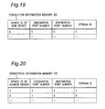
- Fig. 19 is a diagram showing an exemplary connection information table in the connection information memory 25 of the wireless node device 20 of Fig. 1 .
- a device ID of Sink device field is a field containing a device ID of the wireless node device 10 operating as a Sink device to be connected.
- a origination port number field is a field containing an origination port number of the wireless node device 20 itself.
- a destination port number field is a field containing a destination port number of the wireless node device 10 operating as a Sink device.
- a stream ID field is a field containing a stream ID which is assigned upon the resource reserving process described below.
- step S51 of Fig. 11 the controller 11 of the wireless node device 10 determines whether or not a connection-initiation instruction signal has been generated and inputted due to the playback button being pressed on the user input device 16. If YES, then the process goes to step S52; and if NO, then the process goes to step S56. In step S56, the controller 11 determines whether or not a connect request message 70 has been received from the wireless node device 20 due to the playback button being pressed on the user input device 26 of the wireless node device 20 operating as a Source device.
- step S57 If YES, then the process goes to step S57; and if NO, then the process returns to step S51 to wait for a connection-initiation instruction signal or connect request message 70.
- Steps S52 to S55 correspond to the sequence diagram of Fig. 16
- steps S57 to S59 correspond to the sequence diagram of Fig. 15 .
- step S52 the controller 11 determines a destination port used to receive video and audio data signals.
- step S53 the wireless node device 10 operating as a Sink device transmits a connect request message 70A to the wireless node device 20 operating as a Source device, including the destination port number determined in step S52.
- step S54 the wireless node device 10 operating as a Sink device receives a connect response message 80A from the wireless node device 20 operating as a Source device, including an origination port number determined by the wireless node device 20 operating as a Source device.
- step S55 the controller 11 stores a device ID of the wireless node device 20 operating as a Source device, the origination port number included in the connect response message 80A received in step S54, and the destination port number determined in step S52, into the connection information memory 15 in association with one another, and goes to step S3.
- step S57 the controller 11 determines a destination port used to receive video and audio data signals.
- step S58 the controller 11 stores a device ID of the wireless node device 20 operating as a Source device, an origination port number included in the connect request message 70 received in step S56, and the destination port number determined in step S57, into the connection information memory 15 in association with one another.
- step S59 the wireless node device 10 operating as a Sink device transmits a connect response message 80 to the wireless node device 20 operating as a Source device, including the destination port number determined in step S57, and goes to step S3.
- Fig. 20 is a diagram showing an exemplary connection information table in the connection information memory 15 of the wireless node device 10 of Fig. 1 .
- a device ID of Source device field is a field containing a device ID of the wireless node device 20 operating as a Source device to be connected.
- a origination port number field is a field containing an origination port number of the wireless node device 20 operating as a Source device.
- a destination port number field is a field containing a destination port number of the wireless node device 10 itself.
- a stream ID field is a field containing a stream ID which is assigned upon resource reserving process described below, and which is included in a stream start notify message (output format notification message) 90 to be received from the wireless node device 20 operating as a Source device.
- step S2 when there is no free port in step S12, or when receiving a connect response message 80 with a result code indicating a connection failure in step S 14, then the controller 21 may end the process.
- the controller 21 may transmit a connect response message 80A to the wireless node device 10 operating as a Sink device, including a result code indicating a connection failure, and then end the process.
- the connecting process step S2 by a Sink device of Fig. 11 when there is no free port in step S52, or when receiving a connect response message 80A with a result code indicating a connection failure in step S54, then the controller 11 may end the process.
- the controller 11 may transmit a connect response message 80 to the wireless node device 20 operating as a Source device, including a result code indicating a connection failure, and then end the process.
- the ports may be set with priorities, and when there is no free port upon receiving a connect request message 70 or 70A, one of the ports in use that has the lowest priority may be released, or a port that has not been used for a long time may be released, and then the released port may be used.
- FIG. 8 is a flowchart showing a subroutine of the input format obtaining process step S3 by a Source device which is performed by the wireless node device 20 of Fig. 1
- Fig. 12 is a flowchart showing a subroutine of the input format obtaining process step S3 by a Sink device which is performed by the wireless node device 10 of Fig. 1 .
- the wireless node device 20 operating as a Source device obtains information on input formats supported by the wireless node device 10 operating as a Sink device.
- the controller 21 of the wireless node device 20 determines whether or not input format information of the Sink device is already stored in the device capability memory 24. If YES, then the process goes directly to step S4 with omitting steps S22 to S24; and if NO, then the process goes to step S22.
- step S22 the wireless node device 20 operating as a Source device transmits an input format request message to the wireless node device 10 operating as a Sink device.
- the wireless node device 10 operating as a Sink device receives the input format request message from the wireless node device 20 operating as a Source device (step S61 of Fig.
- the controller 11 reads input format information of video and audio data supported by the wireless node device 10 operating as a Sink device, from an EDID-ROM (not shown) of the wireless node device 10. Then, in step S62, the wireless node device 10 operating as a Sink device transmits an input format response message to the wireless node device 20 operating as a Source device, including the read input format information.
- the wireless node device 20 operating as a Source device receives the input format response message from the wireless node device 10 operating as a Sink device (step S23 of Fig. 8 )
- the controller 21 stores the input format information included in the received input format response message, into the device capability memory 24, and goes to step S4.
- the controller 21 of the wireless node device 20 operating as a Source device may store into the device capability memory 24 the input format information obtained during a previous input format obtaining process between the wireless node device 20 and a wireless node device, and accordingly, when transmitting video and audio data signals to the same wireless node device, then as shown in step S21, the controller 21 can omit subsequent steps S22 to S24 of the input format obtaining process.
- the controller 21 refers to the MAC address field of the device capability memory 24, and determines whether or not the same MAC address as that of a wireless node device to be connected is stored in the device capability memory 24, and whether or not corresponding input format information is already stored. In the determination in step S21, it is preferable to refer to the MAC address, and alternatively, other identifiers such as a device ID may be used.
- FIG. 9 is a flowchart showing a subroutine of the resource reserving process step S4 by a Source device which is performed by the wireless node device 20 of Fig. 1
- Fig. 14 is a flowchart showing a subroutine of the resource reserving process step S4 by the management device 31A which is performed by the wireless node device 30 of Fig. 1 .
- the wireless node device 20 operating as a Source device transmits a resource-reservation request message to the wireless node device 30 provided with the management device 31A.
- the payload of the resource-reservation request message includes an operation code indicating that the message is a resource-reservation request message, and also includes the device ID of the wireless node device 10 operating as a Sink device, and a request ID.
- the request ID is assigned to identify which resource-reservation request message is responded by a resource-reservation response message described below. Since the resource-reservation request message is transmitted from the wireless node device 20 operating as a Source device, an origination device ID in its header is the same as the device ID of the Source device.
- the wireless node device 30 identifies the origination and destination of a stream to which resources are to be assigned, based on the device ID of the wireless node device 10 operating as a Sink device, which is included in the payload of the resource-reservation request message, and based on the origination device ID of the message included in the header (i.e., the device ID of the wireless node device 20 operating as a Source device).
- the management device 31A of the wireless node device 30 receives the resource-reservation request message from the wireless node device 20 operating as a Source device, then in step S82, the management device 31A determines whether or not there is any free resource.
- step S83 the management device 31A determines resources assigned to transmit video and audio data signals between the wireless node devices 20 and 10, and also determines a stream ID corresponding to the assigned resources.
- the resources to be assigned include resources required to transmit video and audio data in a determined output format, and if necessary, further include resources required to retransmit the video and audio data. Further, each assigned resource is provided with a stream ID of a different value.
- step S84 the wireless node device 30 transmits a resource-reservation response message to the wireless node device 20 operating as a Source device, including a result code indicating that a resource reservation has been successful, the determined stream ID, and the request ID (the same request ID as that included in the resource-reservation request message).
- step S85 the wireless node device 30 transmits a resource-reservation response message to the wireless node device 20 operating as a Source device, including a result code indicating that a resource reservation has failed, and the request ID.
- step S33 when the wireless node device 20 operating as a Source device receives the resource-reservation response message, then in step S33, the controller 21 of the wireless node device 20 determines whether or not a resource reservation has been successful. If YES, then the process goes to step S34; and if NO, then the process goes to the subsequent output format notifying process step S5.
- step S34 the controller 21 stores the stream ID included in the resource-reservation response message, into the connection information memory 25 in association with the origination port number and destination port number determined in the connecting process step S2, and goes to the subsequent output format notifying process step S5.
- the resource reserving process may be performed by either the wireless node device 20 operating as a Source device, or the wireless node device 10 operating as a Sink device.
- the resource reserving process step S4 can be performed any time after the connecting process step S2, and thus, may be performed in parallel with the input format obtaining process step S3.
- Figs. 10 and 13 shows a subroutine of the output format notifying process step S5 of Fig. 6 .
- Fig. 10 is a flowchart showing a subroutine of the output format notifying process step S5 by a Source device which is performed by the wireless node device 20 of Fig. 1
- Fig. 13 is a flowchart showing a subroutine of the output format notifying process step S5 by a Sink device which is performed by the wireless node device 10 of Fig. 1 .
- the controller 21 of the wireless node device 20 operating as a Source device determines whether or not a resource reservation has been successful, based on the result code included in the resource-reservation response message.
- step S42 the controller 21 selects one format from among input formats obtained at the input format obtaining process step S3, based on a user input through the user input device 26, etc., and determines the format as an output format for transmitting video and audio data signals from the wireless node device 20.
- the controller 21 of the wireless node device 20 may cause the video output device 17A of the wireless node device 10 to display a selection menu including the obtained input formats, and cause a selection result inputted through the user input device 16 to be transmitted from the wireless node device 10 to the wireless node device 20.
- an output format may be automatically determined.
- step S43 the wireless node device 20 operating as a Source device transmits a stream start notify message 90 to the wireless node device 10 operating as a Sink device, including a result code indicating that a resource reservation has been successful, and the output format information determined in step S42. Further, the output format information includes a code indicating an output format.
- step S44 the wireless node device 20 operating as a Source device transmits a stream start notify message 90 to the wireless node device 10 operating as a Sink device, including a result code indicating that a resource reservation has failed, and ends the process.
- step S71 of Fig. 13 the wireless node device 10 operating as a Sink device receives the stream start notify message 90 from the wireless node device 20 operating as a Source device.
- step S72 the controller 11 of the wireless node device 10 operating as a Sink device determines whether or not a resource reservation has been successful, based on the result code included in the stream start notify message 90. If YES, then the controller 11 waits for reception of video and audio data signals; and if NO, then the controller 11 ends the process.
- Step S42 of Fig. 10 of determining an output format can be performed any time after the input format obtaining process step S3, and thus, may be performed before step S41 and in parallel with the resource reserving process step S4.
- steps S43 and S44 of transmitting a stream start notify message require a result code indicating whether or not a resource reservation has been successful, and thus, should be performed after performing the resource reserving process step S4.
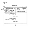
- Fig. 21 is a diagram showing an exemplary format of the stream start notify message 90 of Figs. 10 and 13 .
- the stream start notify message 90 includes an operation code field 91, a result code field 92, a stream ID field 93, a destination port number field 94, a VP field 95, an AP field 96, an origination port number field 97, a reserved field 98, a total data length field 99, type fields 100A, 100B, ..., data length fields 101A, 101B, ..., and data fields 102A, 102B, ....
- a header of the stream start notify message 90 includes respective device IDs of the destination wireless node device 10 and origination wireless node device 20.
- the operation code field 91 is a field containing a code indicating that the message is the stream start notify message 90.
- the result code field 92 is a field containing a code indicating a result of the resource reserving process step S4.
- the stream ID field 93 is a field containing a stream ID obtained in the resource reserving process step S4.
- the destination port number field 94 is a field containing a destination port number.
- the VP field 95 is a field containing a flag indicating whether or not video data is to be transmitted through the port.
- the AP field 96 is a field containing a flag indicating whether or not audio data is to be transmitted through the port.
- the origination port number field 97 is a field containing an origination port number.
- the reserved field 98 is a field reserved for future expansion.
- the total data length field 99 is a field containing the data length of the stream start notify message 90.
- Each of the type fields 100A, 100B, ... is a field containing a value indicating the type of information included in its corresponding data field 102A, 102B, ....
- Each of the data length fields 101A, 101B, ... is a field containing the data length of its corresponding data field 102A, 102B, ....
- Each of the data fields 102A, 102B, ... is a field containing data in a video output format and an audio output format.
- the VP field 95, the AP field 96, the destination port number field 94, and the origination port number field 97 are set with the same values as values set in corresponding fields of a connect response message 80 or connect request message 70A.
- step S6 the wireless node device 20 operating as a Source device, starts to transmit video and audio data signals to the wireless node device 10 operating as a Sink device.
- the controller 21 of the wireless node device 20 operating as a Source device transmits video and audio data signals
- the controller 21 inserts part or all of the device ID of the wireless node device 10 operating as a Sink device, the associated origination port number and destination port number, and the stream ID which are stored in the connection information memory 25, into corresponding fields in a header of each packets of video and audio data signals.
- the device ID can be inserted into a device ID field or destination address containing field in a MAC header
- the destination port number can be inserted into a destination port number field of a video or audio data header
- the stream ID can be inserted into a stream ID field in the MAC header.
- the wireless node device 20 associates its origination port with the video and audio player 27, and the wireless node device 10 associates its destination port with the video output device 17A and the audio output device 17B, and further, the origination port of the wireless node device 20 and the destination port of the wireless node device 10 are also associated with each other. Therefore, video and audio data signals played back by the video and audio player 27 of the wireless node device 20 are transmitted through the origination port of the wireless node device 20 and the destination port of the wireless node device 10, and outputted to the video output device 17A and the audio output device 17B of the wireless node device 10.
- video and audio data signals received through a certain destination port are outputted to the video output device 17A and/or the audio output device 17B associated with the destination port.
- the received video and audio data signals are outputted to the video output device 17A and/or the audio output device 17B associated with a destination port associated with a stream ID set in a stream ID field of a MAC header.
- the respective controllers 11 and 21 of the wireless node devices 10 and 20 release the resources used for transmission, and delete information on the origination port number, the destination port number, and the stream ID in the connection information tables in the connection information memories 15 and 25.
- information in the device capability memories 14 and 24 is held until the wireless node devices 10 and 20 leave the wireless communication system.
- each radio signals 41 and 42 includes both a video data signal and an audio data signal
- the present invention is not limited to the embodiment transmitting both a video data signal and an audio data signal by using resources associated with one stream ID (i.e., resources associated with a pair of an origination port number and a destination port number), and thus, may include an embodiment transmitting only one of a video data signal and an audio data signal.
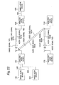
- Fig. 22 is a diagram showing a schematic configuration of a wireless communication system according to a second embodiment of the present invention.
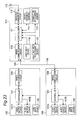
- Figs. 23 to 26 are block diagrams showing detailed configurations of wireless node devices 110, 120, 130, and 170 and wired node devices 140, 150, and 160 of Fig. 22 .
- the present embodiment provides a wireless communication system including more node devices than that of the first embodiment, and including node devices connected through wired interfaces.
- the wired node devices 140, 150, and 160 are AV equipments configured as devices provided with only conventional HDMI wired interfaces, and transmitting video and audio data signals through wired connections.
- the wireless node devices 130 and 170 are AV equipments configured as devices provided with only wireless interfaces, and transmitting video and audio data signals through wireless sections.
- the wireless node devices 110 and 120 are AV equipments configured as devices provided with wireless interfaces and conventional HDMI wired interfaces, and transmitting video and audio data signals through wireless sections and wired connections.
- the wireless node device 110 and the wired node device 140 are connected to each other through an HDMI cable 185
- the wireless node device 110 and the wired node device 160 are connected to each other through an HDMI cable 186
- the wireless node device 120 and the wired node device 150 are connected to each other through an HDMI cable 184.
- the wireless node device 120 transmits a radio signal 181 including a video data signal 181A and an audio data signal 181B to the wireless node device 110.
- the wireless node device 130 transmits a radio signal 182 including a video data signal 182A and an audio data signal 182B to the wireless node device 110, and transmits a radio signal 183 including a video data signal 183A and an audio data signal 183B to the wireless node device 170.
- the transmissions of the respective radio signals 181, 182, and 183 may be multiplexed by using the frequency-division multiplexing in different radio frequency bands, or may be multiplexed by using the time-division multiplexing in different times.
- the wired node device 150 can transmit video and audio data via the wireless node devices 120 and 110 to the wired node devices 140 and 160
- the wireless node device 130 can transmit video and audio data via the wireless node device 110 to the wired node devices 140 and 160.
- the wireless node device 110 operating as a Sink device in a wireless section of the wireless communication system of Fig. 22 is provided with: a wireless communication circuit 112 connected to an antenna 113 and serving as a wireless interface; a video and audio processing device 117 such as an amplifies; a wired communication circuit 118 performing HDMI transmitting processes of video and audio data signals; and a controller 111 controlling these components.
- the controller 111 are further connected with: a device capability memory 114, a connection information memory 115, and a user input device 116. In a manner similar to that of the controller 11 of the wireless node device 10 in the first embodiment, the controller 111 performs the medium access control, resource management, port control, connection management, and application control.
- the wireless communication circuit 112 has a high-speed data reception function of receiving data at a high transmission rate, and a low-speed data transmission and reception function of transmitting and receiving data at a low transmission rate.
- the device capability memory 114, the connection information memory 115, and the user input device 116 are configured in a manner similar to that of the corresponding components of the wireless node device 10 in the first embodiment.
- the wired node device 140 connected to the wireless node device 110 is provided with: a wired communication circuit 148, a video output device 147A such as a display, an audio output device 147B such as speakers, and a controller 141 controlling these components.
- the controller 141 is further connected with a user input device 146.
- the user input device 146, the video output device 147A, and the audio output device 147B are configured in a manner similar to that of the corresponding components of the wireless node device 10 in the first embodiment.
- the wired communication circuit 148 is configured in a manner similar to that of the wired communication circuit 118 of the wireless node device 110.
- the wired node device 160 connected to the wireless node device 110 is provided with: in a manner similar to that of the wired node device 140, a wired communication circuit 168; a video output device 167A; an audio output device 1678; a controller 161 controlling these components; and a user input device 166 connected to the controller 161.
- the wireless node device 110 operates as a receiver adapter for providing a wireless reception function for the wired node devices 140 and 160.
- the wireless node device 120 operating as a Source device in a wireless section of the wireless communication system of Fig. 22 is provided with: a wireless communication circuit 122 connected to an antenna 123 and serving as a wireless interface; a video and audio processing device 127 such as an amplifier; a wired communication circuit 128; and a controller 121 controlling these components.
- the controller 121 are further connected with: a device capability memory 124, a connection information memory 125, and a user input device 126.
- the controller 121 performs the medium access control, resource management, port control, connection management, and application control.
- the wireless communication circuit 122 has a high-speed data transmission function of transmitting data at a high transmission rate, and a low-speed data transmission and reception function of transmitting and receiving data at a low transmission rate.
- the device capability memory 124, the connection information memory 125, and the user input device 126 are configured in a manner similar to that of the corresponding components of the wireless node device 20 in the first embodiment.
- the video and audio processing device 127 is configured in a manner similar to that of the corresponding component of the wireless node device 110. Further, referring to Fig.
- a wired node device 150 connected to the wireless node device 120 is provided with: a wired communication circuit 158; a video and audio player 157 such as a DVD player and an STB; and a controller 151 controlling these components.
- the controller 151 is further connected with a user input device 156.
- the user input device 156 and the video and audio player 157 are configured in a manner similar to that of the corresponding components of the wireless node devices 20 and 30 in the first embodiment.
- the wired communication circuit 158 is configured in a manner similar to that of the wired communication circuit 118 of the wireless node device 110.
- the wireless node device 120 operates as a receiver adapter for providing a wireless transmission function for the wired node device 150.
- the wireless node device 130 operating as another Source device in a wireless section of the wireless communication system of Fig. 22 is provided with: a wireless communication circuit 132 connected to an antenna 133 and serving as a wireless interface; a video and audio player 137 such as a DVD player and an STB; a management device 131A that manages information on wireless resources in the wireless communication system (radio frequency bands or times); and a controller 131 controlling these components.
- the controller 131 are further connected with: a device capability memory 134, a connection information memory 135, and a user input device 136.
- the controller 131 performs the medium access control, resource management, port control, connection management, and application control.
- the management device 131A is configured in a manner similar to that of the management device 31A of the wireless node device 30 in the first embodiment.
- the wireless communication circuit 132, the device capability memory 134, the connection information memory 135, and the user input device 136 are configured in a manner similar to that of the corresponding components of the wireless node device 120.
- the video and audio player 137 is configured in a manner similar to that of the corresponding component of the wired node device 150.
- the wireless node device 170 operating as another Sink device in a wireless section of the wireless communication system of Fig. 22 is provided with: a wireless communication circuit 172 connected to an antenna 173 and serving as a wireless interface; a video output device 177A; an audio output device 177B; and a controller 171 controlling these components.
- the controller 171 are further connected with: a device capability memory 174, a connection information memory 175, and a user input device 176.
- the controller 171 performs the medium access control, resource management, port control, connection management, and application control.
- the wireless communication circuit 172, the device capability memory 174, the connection information memory 175, and the user input device 176 are configured in a manner similar to that of the corresponding components of the wireless node device 110.
- the video output device 177A and the audio output device 177B are configured in a manner similar to that of the corresponding components of the wired node devices 140 and 160.
- each of the wired node devices 140 and 160 and the wireless node device 170 includes both a video output device and an audio output device, but may include only one of the video output device and the audio output device.
- each of the wireless node devices 110 and 170 operating as Sink devices associates a port of its wireless communication circuit (i.e., a destination port) with an output device.
- the wireless communication circuit 112 of the wireless node device 110 has two ports used as destination ports, and associates one port with the video output device 147A and the audio output device 147B of the wired node device 140, and associates the other port with the video output device 167A and the audio output device 167B of the wired node device 160.
- the wireless node device 110 outputs video and audio data signals received at one port of the wireless communication circuit 112, to the wired node device 140, and outputs video and audio data signals received at the other port, to the wired node device 160.
- the wireless communication circuit 172 of the wireless node device 170 has one port used as a destination port, and associates the port with its video output device 177A and the audio output device 177B. Further, in the case that a wireless communication circuit of each of the wireless node devices 110 and 170 has a plurality of ports used as destination ports, distinct ports may be used as a destination port for a video data signal and a destination port for an audio data signal. For example, the wireless node device 110 may output a video data signal received at one port of the wireless communication circuit 112, to the video output device 117A of the wired node device 140, and may output an audio data signal received at the other port, to another wired node device (e.g., an amplifier).
- another wired node device e.g., an amplifier
- the wireless node device 170 may receive a plurality of different video data signals through the respective ports, and the controller 171 may process those video data signals so as to simultaneously display the video data signals on a screen of the video output device (a display) which is divided into a plurality of regions.
- each of the wireless node devices 120 and 130 operating as Source devices associates a port of its wireless communication circuit (i.e., an origination port) with a player.
- the wireless communication circuit 122 of the wireless node device 120 has one port used as an origination port and associates the port with the video and audio player 157 of the wired node device 150
- the wireless communication circuit 132 of the wireless node device 130 has one port used as an origination port and associates the port with its video and audio player 137.
- the wireless node device 120 may associate its ports with different wired node devices.
- the wireless node device 120 associates its origination port with the video and audio player 157 of the wired node device 150
- the wireless node device 110 associates its one destination port with the video output device 147A and the audio output device 147B of the wired node device 140
- the origination port of the wireless node device 120 and the destination port of the wireless node device 110 are also associated with each other as described below. Accordingly, video and audio data signals played back by the video and audio player 157 of the wired node device 150 are transmitted through the origination port of the wireless node device 120 and the destination port of the wireless node device 110 to the video output device 147A and the audio output device 147B of the wired node device 140.
- Fig. 27 is a sequence diagram showing a wireless communicating process which is performed by the wireless communication system of Fig. 22 when the wireless node device 120 of Fig. 22 receives an HDMI Active Source message.
- the wireless communicating process of Fig. 27 is performed, particularly, when a playback button is pressed on the user input device 156 of the wired node device 150 connected by wire to the wireless node device 120, and in response thereto, an Active Source message is transmitted from the wired node device 150 to the wireless node device 120 for starting transmission of video and audio data signals.
- step S91 when the wireless node device 120 has detected reception of an Active Source message, then in step S92, the wireless node devices 110 and 120 perform a connecting process for determining a pair of an origination port number and a destination port number for transmitting video and audio data signals.
- the connecting process step S92 is substantially the same with step S2 of Fig. 6 , except that step S16 of Fig. 7 and step S51 of Fig. 11 are always NO, since a connect request message 70A is never transmitted from the wireless node device 10 operating as a Sink device. Note that in the case that there are a plurality of wireless node devices 110 and 170 operating as Sink devices as shown in Fig.
- the wireless node device 120 operating as a Source device may communicate with a wireless node device which is of a predetermined device (e.g., a TV, display, or amplifier) or a wireless node device connected to a wired node device which is of a predetermined device.
- a predetermined device e.g., a TV, display, or amplifier
- a wireless node device connected to a wired node device which is of a predetermined device.
- an input format obtaining process is performed in which the wireless node device 120 operating as a Source device obtains information on supported input formats from the wireless node device 110 operating as a Sink device.
- the input format obtaining process step S93 is substantially the same with step S3 of Fig.
- the wireless node device 110 determines input format information to be returned to the wireless node device 120, based on input formats supported by the wireless node device 110 and input formats supported by the wired node devices 140 and 160.
- the wireless node device 120 operating as a Source device performs a resource reserving process for reserving radio frequency bands or times for transmitting video and audio data signals, in cooperation with the management device 131A in the wireless node device 130.
- the resource reserving process step S94 is substantially the same with step S4 of Fig. 6 .
- step S95 an output format notifying process is performed in which the wireless node device 120 operating as a Source device notifies the wireless node device 110 operating as a Sink device, of an output format of video and audio data signals.
- the output format notifying process step S95 is substantially the same with step S5 of Fig. 6 .
- step S96 an Active Source message transmitting process is performed in which the wireless node device 120 operating as a Source device encapsulates the Active Source message received in step S91 into a wireless packet, and wirelessly transmits it to the wireless node device 110 operating as a Sink device.
- the wireless node device 110 When the wireless node device 110 receives the Active Source message wirelessly transmitted, the wireless node device 110 transmits the Active Source message to the wired node device 140 or 160. After completion of steps S92 to S96, then in step S97, the wireless node device 120 transmits video and audio data signals to the wireless node device 110.
- Fig. 29 is a diagram showing an exemplary device capability table in the device capability memory 124 of the wireless node device 120 of Fig. 22 .
- the device ID of the wireless node device 110 is "0"
- the device ID of the wireless node device 120 is "1”
- the device ID of the wireless node device 130 is "2”
- the device ID of the wireless node device 170 is "3”.
- Data of a device type field, a high-speed transmission capability field, a high-speed reception capability field, an MAC address field, and a device name field is obtained by performing a device capability obtaining process described with reference to Figs. 2 to 4 .
- Data of an input format field is obtained by performing the input format obtaining process step S93, and in the example shown in Fig.
- the data includes input formats F1 and F2 respectively corresponding to the wired node devices 140 and 160, and an input format F3 corresponding to the wireless node device 170.
- a priority field is a field provided for the wireless node devices 110 and 170 operating as Sink devices, and the field contains data of priority information used for selecting each wireless node device as a destination.
- a Sink device to be used may be selected by performing an output device selecting process described below with reference to Fig. 28 , before playing back video and audio data.
- the priorities are obtained in advance based on user inputs, or determined based on the order in which wireless node devices are detected.
- the priority information is obtained in a manner in which any wireless node device (e.g., the wireless node device 110) displays a selection menu on any video output device (e.g., the video output device 147A of the wired node device 140) for a user to input priorities.
- the obtained priority information is stored in the device capability memories 124 and 134 of the wireless node devices 120 and 130 operating as Source devices. Data of the device ID field, the device type field, the high-speed transmission capability field, the high-speed reception capability field, the MAC address field, and the device name field is shared ' among all of the wireless node devices 110, 120, 130, and 170.
- data of the input format field and the priority field is not stored in the device capability memories 114 and 174 of the wireless node devices 110 and 170 operating as Sink devices, but stored only in the device capability memories 124 and 134 of the wireless node devices 120 and 130 operating as Source devices.
- Fig. 30 is a diagram showing an exemplary connection information table in the connection information memory 125 of the wireless node device 120 of Fig. 22 .
- Fig. 31 is a diagram showing an exemplary connection information table in the connection information memory 135 of the wireless node device 130 of Fig. 22 .
- Fig. 32 is a diagram showing an exemplary connection information table in the connection information memory 115 of the wireless node device 110 of Fig. 22 .
- Fig. 33 is a diagram showing an exemplary connection information table in the connection information memory 175 of the wireless node device 170 of Fig. 22 .
- the connection information tables of Figs. 30 to 33 are configured in a manner similar to that of the connection information tables of Figs. 19 and 20 by performing the connecting process step S92.
- Fig. 28 is a flowchart showing an output device selecting process which is performed by the wireless node device 120 of Fig. 22 .
- the controller 121 of the wireless node device 120 obtains device capability information (see Fig. 2 ), then in step S102, the controller 121 determines whether or not information on any Sink device is stored in the device capability memory 124. If YES, then the process goes to step S103; and if NO, then the process ends.
- step S103 the controller 121 determines whether or not information on a plurality of Sink devices is stored in the device capability memory 24. If YES, then the process goes to step S104; and if NO, then the process goes to step S105.
- step S104 the controller 121 obtains priorities of the respective Sink devices and stores the priorities into the device capability memory 124, and then ends the process.
- step S105 the controller 121 1 assigns a priority of "1" to the Sink device and stores the priority into the device capability memory 124, and then ends the process.
- the controller 121 of the wireless node device 120 selects a wireless node device operating as a Sink device, based on the priorities, and performs steps S92, S93, and S95 to S97 with the selected wireless node device.
- the priorities of Sink devices can be determined by performing the output device selecting process of Fig. 28 , and accordingly, even when there are a plurality of wireless node devices operating as Sink devices, it is possible to select one of the wireless node devices that has the highest priority, and then perform a wireless communicating process.
- the wireless node device 120 operating as a Source device performs a wireless communicating process with one of the wireless node devices 110 and 170 operating as Sink devices, based on the priorities.
- the wireless node device 110 outputs video and audio data signals to the wired node device 140 or 160 according to the association between its port and an output device.
- the wireless node device 120 operating as a Source device considers the wireless node device 110 operating as a receiver adapter and the wireless node device 170 operating as a TV with a wireless reception function to be comparable with each other. Since the priority of the receiver adapter is considered to be comparable with that of the TV, the receiver adapter itself is assigned with a priority, which is compared with priorities assigned to other TVs, etc. for performing a connecting process.
- the wireless node device 120 is connected to the receiver adapter, and thereafter, video is outputted to an output device which is associated with a port in the receiver adapter (e.g., a TV of the wired node device 140 or 160).
- a port in the receiver adapter e.g., a TV of the wired node device 140 or 160.
- Fig. 34 is a diagram showing an exemplary device capability table in a device capability memory 124 of a wireless node device 120 in a wireless communication system according to a modification of the second embodiment of the present invention.
- the device capability table of the present modification includes the respective fields of the device capability table of Fig.
- the output device IDs indicate output interface numbers of the wireless node devices 110 and 170 operating as Sink devices, or indicate model numbers, serial numbers, etc. of the wired node devices 140 and 160 and the wireless node device 170 obtained from their EDID-ROMs (not shown). Accordingly, each node device provided with a video output device or audio output device in the wireless communication system is identified by a pair of a device ID and an output device ID.
- the output device IDs are notified to the wireless node devices 120 and 130 operating as Source devices by the wireless node devices 110 and 170 operating as Sink devices, through a device capability response message 60 used in a device capability obtaining process.
- Fig. 35 to 38 show respective connection information tables of the wireless communication system according to the modification of the second embodiment of the present invention.
- Fig. 35 is a diagram showing an exemplary connection information table in a connection information memory 125 of the wireless node device 120, Fig.
- a device ID and an output device ID identify an origination port number, a destination port number, a stream ID, input formats, and a priority which are associated with one another.
- the wireless node device 120 can communicate with a wireless node device that outputs video and audio data to a video output device or audio output device having the highest priority.
- the wireless node device 110 outputs the video and audio data signals to the wired node device 140 or 160 identified by an output device ID, according to the association between its port number and an output device.
- a video output device and an audio output device in one wireless node device or wired node device may be assigned with different output device IDs.
- video output devices or audio output devices in one wireless node device or wired node device may be assigned with different output device IDs.
- one wireless node device or wired node device may be provided with only one of a video output device and an audio output device, and an output device ID may be assigned for identifying the output device.
- the wired node devices 140 and 160 is hidden from the wireless node device 120 operating as a Source device.
- the wireless node device 120 operating as a Source device is aware of the wired node devices 140 and 160.
- the former configuration is useful in the case that a receiver adapter is connected with only one wired node device, or in the case that a receiver adapter is connected with a plurality of wired node devices, and determines to which one of the wired node devices video and audio data signals are to be outputted.
- the latter configuration is useful in the case that a receiver adapter has two or more output terminals, a transmitter is also informed of this fact, and the transmitter uses the information to select from which output of the receiver adapter signals are to be outputted.
- a tree structure basically with a TV being a root is formed in HDMI.
- a receiver adapter basically does not have two HDMI output terminals, and even if it has, the receiver adapter only switches between its outputs and a transmitter can see only one output.
- each wireless node device described in the first and second embodiments may be implemented as an integrated circuit chip, which is provided with a memory storing a program including the steps involved in the described processes, and a processor executing the program.
- the described functions of each wireless node device may be implemented as a module device, which is provided with a memory storing a program including the steps involved in the described processes, and a processor executing the program.
- the wireless communication devices and wireless communication system according to the present invention have an effect of being able to automatically and wirelessly establish connections among wireless communication devices, and are useful as wireless node devices that efficiently perform video and audio data transmission among the wireless communication devices, etc.
Landscapes
- Engineering & Computer Science (AREA)
- Automation & Control Theory (AREA)
- Computer Networks & Wireless Communication (AREA)
- Signal Processing (AREA)
- Mobile Radio Communication Systems (AREA)
- Two-Way Televisions, Distribution Of Moving Picture Or The Like (AREA)
- Small-Scale Networks (AREA)
Applications Claiming Priority (2)
| Application Number | Priority Date | Filing Date | Title |
|---|---|---|---|
| JP2006338123 | 2006-12-15 | ||
| PCT/JP2007/074226 WO2008072763A1 (fr) | 2006-12-15 | 2007-12-17 | Dispositif de communication radio |
Publications (2)
| Publication Number | Publication Date |
|---|---|
| EP2096796A1 true EP2096796A1 (fr) | 2009-09-02 |
| EP2096796A4 EP2096796A4 (fr) | 2012-12-26 |
Family
ID=39511771
Family Applications (1)
| Application Number | Title | Priority Date | Filing Date |
|---|---|---|---|
| EP07850714A Withdrawn EP2096796A4 (fr) | 2006-12-15 | 2007-12-17 | Dispositif de communication radio |
Country Status (4)
| Country | Link |
|---|---|
| US (1) | US8266658B2 (fr) |
| EP (1) | EP2096796A4 (fr) |
| JP (2) | JP4197191B2 (fr) |
| WO (1) | WO2008072763A1 (fr) |
Cited By (4)
| Publication number | Priority date | Publication date | Assignee | Title |
|---|---|---|---|---|
| CN102098746A (zh) * | 2011-01-25 | 2011-06-15 | 中国科学技术大学 | 一种引入移动资源预留机制的多小区资源分配方法 |
| CN102196227A (zh) * | 2010-03-11 | 2011-09-21 | 株式会社日立制作所 | 视频数据处理装置 |
| US8427525B2 (en) | 2009-05-14 | 2013-04-23 | Panasonic Corporation | Method of transmitting video data for wirelessly transmitting three-dimensional video data |
| US8477179B2 (en) | 2009-05-14 | 2013-07-02 | Panasonic Corporation | Method of transmitting video data for wirelessly transmitting three-dimensional video data |
Families Citing this family (29)
| Publication number | Priority date | Publication date | Assignee | Title |
|---|---|---|---|---|
| JP5341775B2 (ja) * | 2007-12-28 | 2013-11-13 | パナソニック株式会社 | 帯域割り当て方法 |
| US8434087B2 (en) * | 2008-08-29 | 2013-04-30 | International Business Machines Corporation | Distributed acceleration devices management for streams processing |
| JP2010114798A (ja) * | 2008-11-10 | 2010-05-20 | Mitsubishi Electric Corp | 無線伝送システム |
| EP2352288B1 (fr) * | 2008-11-25 | 2018-07-18 | ZTE Corporation | Procédé destiné à transmettre et recevoir les données de service de télévision sur dispositif mobile |
| JP2010130496A (ja) * | 2008-11-28 | 2010-06-10 | Toshiba Corp | コンテンツデータ入出力装置及びコンテンツデータ入出力方法 |
| JP4621787B2 (ja) * | 2009-05-19 | 2011-01-26 | 株式会社東芝 | 無線転送装置および無線転送方法 |
| JPWO2010140199A1 (ja) * | 2009-06-01 | 2012-11-15 | パナソニック株式会社 | 映像データの伝送方法 |
| EP3595270B1 (fr) * | 2009-08-21 | 2021-06-16 | Samsung Electronics Co., Ltd. | Procédé et appareil de génération ou d'utilisation d'informations sur l'activité d'interaction |
| RU2500087C2 (ru) | 2009-08-21 | 2013-11-27 | Самсунг Электроникс Ко., Лтд. | Способ и устройство для формирования или использования информации относительно интерактивных операций |
| JP5560282B2 (ja) * | 2009-10-22 | 2014-07-23 | パナソニック株式会社 | 無線伝送方法、無線伝送装置、無線伝送システム、プログラム、及び集積回路 |
| JP2011097274A (ja) * | 2009-10-28 | 2011-05-12 | Toshiba Corp | 通信装置 |
| JP5692990B2 (ja) * | 2009-11-09 | 2015-04-01 | キヤノン株式会社 | 無線通信装置 |
| KR101767262B1 (ko) * | 2009-11-09 | 2017-08-11 | 삼성전자주식회사 | UPnP를 이용한 입력 시스템에서 입력 방식을 변경하기 위한 방법 및 장치 |
| WO2011070720A1 (fr) * | 2009-12-09 | 2011-06-16 | パナソニック株式会社 | Dispositif de reproduction, dispositif d'affichage, systeme de reseau av, procede de reproduction, programme, et circuit integre |
| JP4802289B1 (ja) * | 2010-05-31 | 2011-10-26 | 株式会社東芝 | 電子機器及び通信システム |
| US9078289B2 (en) * | 2011-05-03 | 2015-07-07 | Smsc Holdings S.A.R.L. | Systems and methods for flexible wireless connectivity of devices |
| JP5690206B2 (ja) * | 2011-05-11 | 2015-03-25 | オリンパス株式会社 | 無線端末および無線システム |
| JP5909881B2 (ja) * | 2011-06-01 | 2016-04-27 | ソニー株式会社 | 通信装置及び通信方法、並びに通信システム |
| US8918569B2 (en) * | 2011-08-10 | 2014-12-23 | Intel Corporation | Streaming audio visual content simultaneously to different topologies on a wireless adapter |
| KR20130058962A (ko) * | 2011-11-28 | 2013-06-05 | 한국전자통신연구원 | 지그비 네트워크 표준 프로토콜 기반의 무선 영상 통신 장치 및 방법 |
| JP6212882B2 (ja) | 2013-03-13 | 2017-10-18 | 株式会社リコー | 通信システム、送信装置及び受信装置並びに通信方法 |
| JP5749318B2 (ja) * | 2013-11-13 | 2015-07-15 | 三菱電機株式会社 | 無線伝送システム |
| JP6565138B2 (ja) * | 2014-06-23 | 2019-08-28 | 株式会社リコー | 通信システム |
| JP6467822B2 (ja) * | 2014-08-29 | 2019-02-13 | セイコーエプソン株式会社 | 表示システム、送信装置、及び、表示システムの制御方法 |
| WO2016163777A1 (fr) * | 2015-04-08 | 2016-10-13 | 삼성전자 주식회사 | Procédé et appareil pour transmettre et recevoir des données dans un système de communication sans fil |
| US20160350058A1 (en) * | 2015-06-01 | 2016-12-01 | Intel Corporation | Wireless display adapter device |
| JP6432659B2 (ja) * | 2017-09-21 | 2018-12-05 | 株式会社リコー | 通信システム |
| US11082557B1 (en) * | 2020-03-31 | 2021-08-03 | T-Mobile Usa, Inc. | Announcement or advertisement in text or video format for real time text or video calls |
| US20240349322A1 (en) | 2021-08-04 | 2024-10-17 | Nippon Telegraph And Telephone Corporation | Communication system and communication method |
Family Cites Families (14)
| Publication number | Priority date | Publication date | Assignee | Title |
|---|---|---|---|---|
| WO2002027472A1 (fr) * | 2000-09-27 | 2002-04-04 | Thomson Licensing S.A. | Architecture pour optimiser des etats de sortie audio et video de dispositifs multimedia |
| US7698723B2 (en) * | 2000-12-28 | 2010-04-13 | At&T Intellectual Property I, L.P. | System and method for multimedia on demand services |
| US7218626B2 (en) * | 2001-05-29 | 2007-05-15 | Interdigital Technology Corporation | System and method for reducing information communicated between universal mobile telecommunication system multimedia capable units |
| JP3869712B2 (ja) * | 2001-12-14 | 2007-01-17 | 株式会社日立国際電気 | 無線ブリッジ |
| JP4369214B2 (ja) | 2002-12-11 | 2009-11-18 | パナソニック株式会社 | Avシステム |
| GB0329202D0 (en) * | 2003-12-17 | 2004-01-21 | Koninkl Philips Electronics Nv | Automated signal selection |
| JP2006005491A (ja) | 2004-06-15 | 2006-01-05 | Canon Inc | 通信装置及び制御方法 |
| JP2006101428A (ja) * | 2004-09-30 | 2006-04-13 | National Institute Of Information & Communication Technology | 無線ネットワークの制御装置及び制御方法、制御プログラム並びに記録媒体 |
| US20060159091A1 (en) * | 2005-01-19 | 2006-07-20 | Arjen Boers | Active multicast information protocol |
| US7728911B2 (en) * | 2005-01-26 | 2010-06-01 | Hewlett-Packard Development Company, L.P. | Positively indicating to user whether signal has been detected on each video input |
| US20060236354A1 (en) * | 2005-04-18 | 2006-10-19 | Sehat Sutardja | Wireless audio for entertainment systems |
| JP4660278B2 (ja) * | 2005-05-24 | 2011-03-30 | 株式会社東芝 | 複数の無線通信部を搭載した無線通信端末 |
| US20070186015A1 (en) * | 2006-02-08 | 2007-08-09 | Taft Frederick D | Custom edid content generation system and method |
| US7765599B2 (en) * | 2006-06-13 | 2010-07-27 | Intel Corporation | Multimedia transmitter, multimedia receiver, multimedia transmission system, and method for securely transmitting multimedia content over a wireless link |
-
2007
- 2007-12-17 JP JP2008525738A patent/JP4197191B2/ja not_active Expired - Fee Related
- 2007-12-17 WO PCT/JP2007/074226 patent/WO2008072763A1/fr not_active Ceased
- 2007-12-17 US US12/519,009 patent/US8266658B2/en not_active Expired - Fee Related
- 2007-12-17 EP EP07850714A patent/EP2096796A4/fr not_active Withdrawn
-
2008
- 2008-05-22 JP JP2008133960A patent/JP5084607B2/ja not_active Expired - Fee Related
Cited By (5)
| Publication number | Priority date | Publication date | Assignee | Title |
|---|---|---|---|---|
| US8427525B2 (en) | 2009-05-14 | 2013-04-23 | Panasonic Corporation | Method of transmitting video data for wirelessly transmitting three-dimensional video data |
| US8477179B2 (en) | 2009-05-14 | 2013-07-02 | Panasonic Corporation | Method of transmitting video data for wirelessly transmitting three-dimensional video data |
| CN102196227A (zh) * | 2010-03-11 | 2011-09-21 | 株式会社日立制作所 | 视频数据处理装置 |
| CN102098746A (zh) * | 2011-01-25 | 2011-06-15 | 中国科学技术大学 | 一种引入移动资源预留机制的多小区资源分配方法 |
| CN102098746B (zh) * | 2011-01-25 | 2013-08-07 | 中国科学技术大学 | 一种引入移动资源预留机制的多小区资源分配方法 |
Also Published As
| Publication number | Publication date |
|---|---|
| JP5084607B2 (ja) | 2012-11-28 |
| JP2008252929A (ja) | 2008-10-16 |
| EP2096796A4 (fr) | 2012-12-26 |
| US8266658B2 (en) | 2012-09-11 |
| JP4197191B2 (ja) | 2008-12-17 |
| JPWO2008072763A1 (ja) | 2010-04-02 |
| WO2008072763A1 (fr) | 2008-06-19 |
| US20100050214A1 (en) | 2010-02-25 |
Similar Documents
| Publication | Publication Date | Title |
|---|---|---|
| EP2096796A1 (fr) | Dispositif de communication radio | |
| RU2480943C1 (ru) | Система беспроводной передачи, устройство-ретранслятор, беспроводное устройство-получатель и беспроводное устройство-источник | |
| EP2026504B1 (fr) | Procédé d'affectation d'adresse logique | |
| US8675682B2 (en) | Wireless communication device for processing packet including at least one of video output format of video data and audio output format of audio data | |
| US8493511B2 (en) | Display system, display device, and repeater | |
| US8365232B2 (en) | Method, device, system, program, and integrated circuit for wireless transmission | |
| CN102714829A (zh) | 电子设备及其操作方法 | |
| JP2008035517A (ja) | 無線通信システム | |
| JP4193013B2 (ja) | 情報出力装置および接続関係管理方法 | |
| US9137835B2 (en) | Communication apparatus, communication method, and communication system | |
| JP2011019262A (ja) | 無線伝送システム | |
| US20070169150A1 (en) | Automated signal selection | |
| JP2010279072A (ja) | 無線伝送システム | |
| JP2015136157A (ja) | 携帯端末装置 | |
| JP5183694B2 (ja) | 無線伝送システム | |
| JP2010259119A (ja) | 無線伝送システム | |
| WO2010047124A1 (fr) | Contrôleur de dispositif multimédia, dispositif source, dispositif de synchronisation, et système de transmission | |
| HK1167545A (en) | Radio transmission system, relay device, radio synchronization device, and radio source device |
Legal Events
| Date | Code | Title | Description |
|---|---|---|---|
| PUAI | Public reference made under article 153(3) epc to a published international application that has entered the european phase |
Free format text: ORIGINAL CODE: 0009012 |
|
| 17P | Request for examination filed |
Effective date: 20090715 |
|
| AK | Designated contracting states |
Kind code of ref document: A1 Designated state(s): AT BE BG CH CY CZ DE DK EE ES FI FR GB GR HU IE IS IT LI LT LU LV MC MT NL PL PT RO SE SI SK TR |
|
| DAX | Request for extension of the european patent (deleted) | ||
| A4 | Supplementary search report drawn up and despatched |
Effective date: 20121126 |
|
| RIC1 | Information provided on ipc code assigned before grant |
Ipc: H04L 12/28 20060101AFI20121120BHEP |
|
| 17Q | First examination report despatched |
Effective date: 20140106 |
|
| GRAP | Despatch of communication of intention to grant a patent |
Free format text: ORIGINAL CODE: EPIDOSNIGR1 |
|
| INTG | Intention to grant announced |
Effective date: 20160923 |
|
| STAA | Information on the status of an ep patent application or granted ep patent |
Free format text: STATUS: GRANT OF PATENT IS INTENDED |
|
| STAA | Information on the status of an ep patent application or granted ep patent |
Free format text: STATUS: THE APPLICATION IS DEEMED TO BE WITHDRAWN |
|
| 18D | Application deemed to be withdrawn |
Effective date: 20170204 |