EP2096855B1 - Bildlesevorrichtung, Bildleseverfahren und Bilderzeugungsvorrichtung mit der Bildlesevorrichtung - Google Patents
Bildlesevorrichtung, Bildleseverfahren und Bilderzeugungsvorrichtung mit der Bildlesevorrichtung Download PDFInfo
- Publication number
- EP2096855B1 EP2096855B1 EP09250407A EP09250407A EP2096855B1 EP 2096855 B1 EP2096855 B1 EP 2096855B1 EP 09250407 A EP09250407 A EP 09250407A EP 09250407 A EP09250407 A EP 09250407A EP 2096855 B1 EP2096855 B1 EP 2096855B1
- Authority
- EP
- European Patent Office
- Prior art keywords
- carriage
- image reading
- reading device
- home position
- energy
- Prior art date
- Legal status (The legal status is an assumption and is not a legal conclusion. Google has not performed a legal analysis and makes no representation as to the accuracy of the status listed.)
- Ceased
Links
- 238000000034 method Methods 0.000 title claims description 37
- 230000003287 optical effect Effects 0.000 claims description 10
- 239000011521 glass Substances 0.000 claims description 5
- 230000008569 process Effects 0.000 description 26
- 239000000470 constituent Substances 0.000 description 3
- 238000001514 detection method Methods 0.000 description 3
- 238000003384 imaging method Methods 0.000 description 3
- 238000010586 diagram Methods 0.000 description 2
- 238000003702 image correction Methods 0.000 description 2
- 230000009467 reduction Effects 0.000 description 2
- 230000005540 biological transmission Effects 0.000 description 1
- 230000000052 comparative effect Effects 0.000 description 1
- 230000003247 decreasing effect Effects 0.000 description 1
- 238000001914 filtration Methods 0.000 description 1
- 238000005286 illumination Methods 0.000 description 1
- 239000000463 material Substances 0.000 description 1
- 230000007246 mechanism Effects 0.000 description 1
- 238000012986 modification Methods 0.000 description 1
- 230000004048 modification Effects 0.000 description 1
- 238000011144 upstream manufacturing Methods 0.000 description 1
Images


Classifications
-
- H—ELECTRICITY
- H04—ELECTRIC COMMUNICATION TECHNIQUE
- H04N—PICTORIAL COMMUNICATION, e.g. TELEVISION
- H04N1/00—Scanning, transmission or reproduction of documents or the like, e.g. facsimile transmission; Details thereof
- H04N1/04—Scanning arrangements, i.e. arrangements for the displacement of active reading or reproducing elements relative to the original or reproducing medium, or vice versa
- H04N1/047—Detection, control or error compensation of scanning velocity or position
-
- H—ELECTRICITY
- H04—ELECTRIC COMMUNICATION TECHNIQUE
- H04N—PICTORIAL COMMUNICATION, e.g. TELEVISION
- H04N1/00—Scanning, transmission or reproduction of documents or the like, e.g. facsimile transmission; Details thereof
- H04N1/00002—Diagnosis, testing or measuring; Detecting, analysing or monitoring not otherwise provided for
-
- H—ELECTRICITY
- H04—ELECTRIC COMMUNICATION TECHNIQUE
- H04N—PICTORIAL COMMUNICATION, e.g. TELEVISION
- H04N1/00—Scanning, transmission or reproduction of documents or the like, e.g. facsimile transmission; Details thereof
- H04N1/00002—Diagnosis, testing or measuring; Detecting, analysing or monitoring not otherwise provided for
- H04N1/00007—Diagnosis, testing or measuring; Detecting, analysing or monitoring not otherwise provided for relating to particular apparatus or devices
- H04N1/00018—Scanning arrangements
-
- H—ELECTRICITY
- H04—ELECTRIC COMMUNICATION TECHNIQUE
- H04N—PICTORIAL COMMUNICATION, e.g. TELEVISION
- H04N1/00—Scanning, transmission or reproduction of documents or the like, e.g. facsimile transmission; Details thereof
- H04N1/00002—Diagnosis, testing or measuring; Detecting, analysing or monitoring not otherwise provided for
- H04N1/00026—Methods therefor
- H04N1/00045—Methods therefor using a reference pattern designed for the purpose, e.g. a test chart
-
- H—ELECTRICITY
- H04—ELECTRIC COMMUNICATION TECHNIQUE
- H04N—PICTORIAL COMMUNICATION, e.g. TELEVISION
- H04N1/00—Scanning, transmission or reproduction of documents or the like, e.g. facsimile transmission; Details thereof
- H04N1/00885—Power supply means, e.g. arrangements for the control of power supply to the apparatus or components thereof
- H04N1/00888—Control thereof
- H04N1/00891—Switching on or off, e.g. for saving power when not in use
-
- H—ELECTRICITY
- H04—ELECTRIC COMMUNICATION TECHNIQUE
- H04N—PICTORIAL COMMUNICATION, e.g. TELEVISION
- H04N1/00—Scanning, transmission or reproduction of documents or the like, e.g. facsimile transmission; Details thereof
- H04N1/00885—Power supply means, e.g. arrangements for the control of power supply to the apparatus or components thereof
- H04N1/00888—Control thereof
- H04N1/00896—Control thereof using a low-power mode, e.g. standby
-
- H—ELECTRICITY
- H04—ELECTRIC COMMUNICATION TECHNIQUE
- H04N—PICTORIAL COMMUNICATION, e.g. TELEVISION
- H04N1/00—Scanning, transmission or reproduction of documents or the like, e.g. facsimile transmission; Details thereof
- H04N1/00912—Arrangements for controlling a still picture apparatus or components thereof not otherwise provided for
- H04N1/00928—Initialisation or control of normal start-up or shut-down, i.e. non failure or error related
-
- H—ELECTRICITY
- H04—ELECTRIC COMMUNICATION TECHNIQUE
- H04N—PICTORIAL COMMUNICATION, e.g. TELEVISION
- H04N1/00—Scanning, transmission or reproduction of documents or the like, e.g. facsimile transmission; Details thereof
- H04N1/00912—Arrangements for controlling a still picture apparatus or components thereof not otherwise provided for
- H04N1/00931—Synchronising different operations or sub-apparatus, e.g. controlling on-times taking into account different warm-up times
-
- H—ELECTRICITY
- H04—ELECTRIC COMMUNICATION TECHNIQUE
- H04N—PICTORIAL COMMUNICATION, e.g. TELEVISION
- H04N2201/00—Indexing scheme relating to scanning, transmission or reproduction of documents or the like, and to details thereof
- H04N2201/04—Scanning arrangements
- H04N2201/0402—Arrangements not specific to a particular one of the scanning methods covered by groups H04N1/04 - H04N1/207
- H04N2201/0462—Arrangements not specific to a particular one of the scanning methods covered by groups H04N1/04 - H04N1/207 for reducing inactive scanning periods, e.g. increasing speed of carriage during return movement
-
- H—ELECTRICITY
- H04—ELECTRIC COMMUNICATION TECHNIQUE
- H04N—PICTORIAL COMMUNICATION, e.g. TELEVISION
- H04N2201/00—Indexing scheme relating to scanning, transmission or reproduction of documents or the like, and to details thereof
- H04N2201/04—Scanning arrangements
- H04N2201/047—Detection, control or error compensation of scanning velocity or position
- H04N2201/04753—Control or error compensation of scanning position or velocity
- H04N2201/04755—Control or error compensation of scanning position or velocity by controlling the position or movement of a scanning element or carriage, e.g. of a polygonal mirror, of a drive motor
-
- H—ELECTRICITY
- H04—ELECTRIC COMMUNICATION TECHNIQUE
- H04N—PICTORIAL COMMUNICATION, e.g. TELEVISION
- H04N2201/00—Indexing scheme relating to scanning, transmission or reproduction of documents or the like, and to details thereof
- H04N2201/04—Scanning arrangements
- H04N2201/047—Detection, control or error compensation of scanning velocity or position
- H04N2201/04753—Control or error compensation of scanning position or velocity
- H04N2201/04791—Control or error compensation of scanning position or velocity in the sub-scan direction
Definitions
- Exemplary aspects of the present invention generally relate to an image reading device to read image data from an original document placed on a document stand by scanning it using a carriage driven by a pulse motor, an image reading method, and an image forming apparatus including the image reading device.
- the image reading device When not in operation, the image reading device is generally either in a power-off mode, in which all power supply is turned off, or in an energy-saving mode, in which power is only partially supplied. Specifically, the image reading device enters the power-off mode when a main power source is turned off to shut down the image reading device. By contrast, the image reading device enters the energy-saving mode when a next operation is not performed for a certain period of time after completion of the previous operation.
- minimum power is supplied to a minimum number of units to operate a control circuit, and no power is supplied to the rest of the units.
- a shorter wake-up time is especially required when the image reading device is returned to the active mode from the energy-saving mode. How this shorter wake-up time is accomplished requires a detailed discussion of the structure and operation of a typical image reading device, provided below.
- the image reading device typically includes a lamp, a reflector, a first carriage including a first mirror, a second carriage including second and third mirrors, a home position sensor to detect whether or not the first carriage is positioned at a home position, a contact glass on which an original document is to be placed, a reference whiteboard used for generating shading data and adjusting a reference level, optical elements such as a lens and a CCD, a motor for moving the first and second carriages, and so forth.
- the first and second carriages are moved in a sub-scanning direction to read data on the reference whiteboard and the original document. When not scanning, the first and second carriages stay at the home position.
- FIG. 1A is a top view illustrating a related-art image reading device.
- FIG. 1B is a front view illustrating the related-art image reading device illustrated in FIG. 1A in which first and second carriages are positioned at a home position.
- FIG. 1C is a view illustrating a detection result output from a home position sensor in which a sub-scanning direction of the carriages is represented by a horizontal axis.
- an image reading device 1 includes a document stand 2, a contact glass, not shown, provided to the document stand 2, and a reference whiteboard 3 provided on a bottom surface of the document stand 2.
- the reference whiteboard 3 is provided upstream from the contact glass relative to a direction of movement of a carriage assembly.
- the carriage assembly includes a first carriage 4 and a second carriage 5.
- the first carriage 4 includes a lamp 6 serving as an illumination light source, and a first mirror 7 to reflect light reflected from an original document.
- the second carriage 5 includes second and third mirrors 8 and 9 to direct the light reflected from the first mirror 7 to an imaging lens 10.
- the first and second carriages 4 and 5 are moved at a speed ratio of 2 to 1, and a distance from the first and second carriages 4 and 5 to a CCD 11 is set to be constant.
- the CCD 11 reads an image of the original document, and is provided on a sensor board 12.
- the image of the original document formed by the imaging lens 10 is focused on an imaging surface of the CCD 11 and read by the CCD 11.
- data on the reference whiteboard 3 and the original document are read as image data.
- the first and second carriages 4 and 5 are positioned at a home position 13 when not scanning.
- the home position 13 is located a certain distance apart from where a home position sensor 14 is switched from OFF to ON when detecting that the first carriage 4 passes the home position sensor 14.
- the lamp 6, the first mirror 7, and the second and third mirrors 8 and 9 hereinafter serve as optical elements.
- the first and second carriages 4 and 5 are moved by a driving force transmission mechanism, not shown, including a pulse motor.
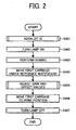
- FIG. 2 is a flowchart illustrating a process to return the image reading device 1 from the power-off mode or the energy-saving mode to the active mode.
- the same process is performed to return the image reading device 1 from the power-off mode and the energy-saving mode to the active mode.
- ICs integrated circuits
- the lamp 6 is turned on, and homing is performed at S403.
- the term "homing" as used in this specification includes relocation of the first carriage 4 at the home position 13. Homing includes two different processes depending on a state of the home position sensor 14 before homing, as described below.
- the first carriage 4 In a case in which the home position sensor 14 is switched ON before homing, the first carriage 4 is moved to a position where the home position sensor 14 is switched OFF. Subsequently, a direction of movement of the first carriage 4 is reversed when the home position sensor 14 is switched OFF, and moved until the home position sensor 14 is switched ON. A pulse is counted from the position where the home position sensor 14 is switched ON from OFF to place the carriage 4 at the home position 13.
- the first carriage 4 is moved in a direction such that the home position sensor 14 is switched ON.
- a pulse is counted from the position where the home position sensor 14 is switched ON from OFF to place the carriage 4 at the home position 13.
- the first carriage 4 is moved under the reference whiteboard 3 from the home position 13 to start initialization.
- initialization is performed to initialize the ICs and adjust gain and offset values.
- the adjusted gain value and a black level are confirmed and the first carriage 4 is moved to the home position 13.
- the lamp 6 is turned off, and the image reading device 1 is now in the active mode and ready to start reading images.
- the motor for driving the first carriage 4 is not activated during the power-off mode and the energy-saving mode. Consequently, the first carriage 4 may be moved from the home position 13 due to vibration applied while, for example, in transit. As a result, homing is required to be performed to move the first carriage 4 to the home position 13 when the image reading device 1 is returned to the active mode. However, because a moving speed of the first carriage 4 during homing is constant and slow, a longer time is required to complete homing.
- the image reading device 1 does not enter the energy-saving mode while in transit. Therefore, it is assumed that the first carriage 4 does not move much from the home position 13 during the energy-saving mode due to vibration. However, during the energy-saving mode, the first carriage 4 is likely to be positioned where it is positioned immediately before the image reading device 1 enters the energy-saving mode. Consequently, homing is still required to be performed when the image reading device 1 is returned from the energy-saving mode to the active mode.
- Prior art EP-A-1 261 193 describes a method for "reading the reference white plate while moving, and then controls the driving device to decelerate the image reading system when the image reading system is moved to the reference white plate reading position.”
- Prior art EP-A-1 816 847 describes a system in which "the scanning head moves to the home position at a faster speed than a predetermined reference speed if the scanning head is distanced farther from the home position than a predetermined.”
- an image reading device an image reading method, and an image forming apparatus including the image reading device as defined in the appended claims.
- an image reading device includes a configuration substantially similar to that of the image reading device 1 illustrated in FIG. 1 . Therefore, the same reference numerals as those used in FIG. 1 are assigned to the similar components in the image reading device according to illustrative embodiments, and detailed explanation thereof is omitted.
- FIG. 3 is a block diagram illustrating a configuration of a control circuit included in an image reading device 1 according to illustrative embodiments.
- a CPU 20 serving as a control unit to control an image forming sequence and systems in the image reading device 1 also controls initialization such as homing and adjustment of signal characteristics or read images.
- the CPU 20 controls a motor driver 22, a CCD 11 provided on a sensor board 12, an image processing unit 23, and an NVRAM 24.
- the motor driver 22 drives a scanner motor 21 for moving first and second carriages 4 and 5 each provided with an optical reading system including lamps and mirrors.
- the sensor board 12 includes the CCD 11 and black and white level control units thereon.
- the image processing unit 23 digitalizes image data read and sent by the sensor board 12.
- the NVRAM 24 stores data necessary for initialization.
- the CPU 20 receives a detection signal used for homing from a home position sensor 14.
- the image processing unit 23 applies image correction including shading, gamma correction, scaling, filtering, and so forth to the digitalized data of the image read and sent by the sensor board 12.
- the digitalized data to which the image correction is applied is then sent to a writing unit, not shown, to be output.
- the image processing unit 23 detects black and white level data used for obtaining an adjusted value for clamp and gain correction performed by a signal processing unit, not shown, provided on the sensor board 12, based on the digitalized data of the image sent from the sensor board 12. Thereafter, the data thus detected is output to the CPU 20 for feedback.
- the scanner motor 21 includes a pulse motor (a stepping motor) driven by a driving pulse.
- FIG. 4 is a flowchart illustrating a process performed by the CPU 20 when the image reading device 1 enters the energy-saving mode.
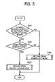
- FIG. 5 is a flowchart illustrating a process to return the image reading device 1 to the active mode from the energy-saving mode.
- the first carriage 4 is moved under a reference whiteboard 3. Thereafter, at S102, the image reading device 1 enters the energy-saving mode. In other words, the first carriage 4 is moved under the reference whiteboard 3 immediately before the image reading device 1 enters the energy-saving mode.
- the CPU 20 confirms whether or not the image reading device 1 is to be returned to the active mode from the energy saving mode.
- the CPU 20 confirms whether or not the home position sensor 14 is turned off.
- the home position sensor 14 is turned off (YES at S202)
- the image reading device 1 is returned to the active mode from the energy-saving mode.
- the image reading device 1 is returned to the active mode from the power-off mode in the same way as the process illustrated in FIG. 2 .
- the home position sensor 14 when the home position sensor 14 is turned on, it means that the first carriage 4 is positioned near a home position 13. Therefore, it is clear that the first carriage 4 is not positioned under the reference whiteboard 3. Accordingly, a process that is the same as that to return the image reading device 1 to the active mode from the power-off mode is performed.
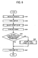
- FIG. 6 is a flowchart illustrating a process to return the image reading device 1 to the active mode from the energy-saving mode performed as a sub-sequence of S203 in the process illustrated in FIG. 5 .
- the integrated circuit is initialized.
- a register of the integrated circuit is initialized.
- a lamp 6 is turned on to read data from the reference whiteboard 3 and adjust a gain value to obtain a predetermined target value.
- an offset value is adjusted. In a similar way as adjustment of the gain value, the offset value is adjusted such that a black level reaches a predetermined target value.
- homing is performed.
- a distance of movement of the first carriage 4 is accurately obtained by counting a pulse to the home position 13.
- the pulse is counted as follows: First, an initial value of a counter provided to the CPU 20 is obtained before the first carriage 4 is moved, and the initial value thus obtained is held as a variable POSCNTCK 1. Next, a counted value of the counter is obtained after homing is performed to move the first carriage 4 to the home position 13. The counted value thus obtained is held as a variable POSCNTCK 2. Then, a pulse during movement of the first carriage 4 is detected from a difference between the variables POSCNTCK 1 and POSCNTCK 2.
- the distance of movement of the first carriage 4 during homing is calculated based on the pulse during the movement of the first carriage 4 thus obtained and an amount of movement of the motor per pulse, and at S305, the CPU 20 determines whether or not the first carriage 4 was positioned under the reference whiteboard 3. In other words, the CPU 20 determines whether or not the first carriage 4 was positioned under the reference whiteboard 3 based on the distance of movement of the first carriage 4 during homing thus calculated.
- the processes of S403 and S404 in FIG. 2 performed by the related-art image reading device can be omitted.
- the time required to return the image reading device 1 to the active mode from the energy-saving mode can be reduced.
- the process to return the image reading device 1 to the active mode from the power-off mode is performed so that the adjusted values can be obtained by reading the reference whiteboard 3.
- the adjusted gain and offset values obtained at previous adjustment may be used. Although accuracy of the gain and offset values is slightly decreased, the time required to return the image reading device 1 to the active mode from the energy-saving mode can be reduced.
- the image reading device 1 may be configured such that the user can select whether to return the image reading device 1 to the active mode from the power-off mode or to perform homing using the gain and offset values adjusted at previous adjustment in the case in which the first carriage 4 is not positioned under the reference whiteboard 3 when the image reading device 1 is returned to the active mode from the energy-saving mode.
- the selection may be performed through a control panel, not shown, provided to the image reading device 1, or a control panel provided to an image forming apparatus.
- the image reading device 1 is described above as a scanner, the image reading device 1 according to the foregoing illustrative embodiments can be effectively applied to an image forming apparatus (such as a copier) including the scanner.
- an image forming apparatus such as a copier
- the first carriage 4 is moved under the reference whiteboard 3 immediately before the energy-saving mode is activated. Accordingly, it is not necessary to perform homing and to move the first carriage 4 under the reference whiteboard 3 when the image reading device 1 is returned to the active mode from the energy-saving mode. As a result, the time required for returning the image reading device 1 to the active mode from the energy-saving mode can be reduced.
- the pulse of the motor is counted at homing after initialization so that the distance between the position of the first carriage 4 when initialization is performed and the home position 13 is reliably obtained.
- the time required for returning the image reading device 1 to the active mode from the energy-saving mode can be reduced even when the first carriage 4 is not positioned under the reference whiteboard 3.
- the pulse of the pulse motor for moving the first carriage 4 is counted when the image reading device 1 is returned to the active mode from the power-off mode or the energy-saving mode, so that the position of the first carriage 4 is reliably obtained when the image reading device 1 is returned to the active mode.
- the different process is performed depending on whether the image reading device 1 is returned to the active mode from the power-off mode or the energy-saving mode. As a result, the time required for returning the image reading device 1 to the active mode from the energy-saving mode can be reduced.
- the first carriage 4 is moved under the reference whiteboard 3 in advance when the image reading device 1 enters the energy-saving mode, the time required for returning the image reading device 1 to the active mode from the energy-saving mode can be reduced.
- the different process is performed when the image reading device 1 is returned from the power-off mode and the energy-saving mode. Specifically, when the image reading device 1 is returned to the active mode from the power-off mode, homing is performed first in a similar way as the image reading device of the related-art. By contrast, when the image reading device 1 is returned to the active mode from the energy-saving mode, it is not necessary to perform homing in the image reading device 1 according to the foregoing illustrative embodiments, so that the time required for returning the image reading device 1 to the active mode from the energy-saving mode can be reduced.
- the pulse to the home position 13 is counted. As a result, it can be reliably determined whether or not the first carriage 4 is positioned under the reference whiteboard 3 when the process to return the image reading device 1 to the active mode from the energy-saving mode is started.
- homing is performed using the previously adjusted gain and offset values, resulting in a reduction in the time required to return the image reading device 1 to the active mode from the energy-saving mode.
Landscapes
- Engineering & Computer Science (AREA)
- Multimedia (AREA)
- Signal Processing (AREA)
- Health & Medical Sciences (AREA)
- Biomedical Technology (AREA)
- General Health & Medical Sciences (AREA)
- Facsimile Scanning Arrangements (AREA)
- Image Processing (AREA)
Claims (11)
- Bildlesevorrichtung (1), die umfasst:einen ersten Schlitten (4), der optische Elemente zum Lesen eines Bildes eines Dokuments umfasst;einen zweiten Schlitten (5), der optische Elemente zum Lesen eines Bildes des Dokuments umfasst;eine Schlittenantriebseinheit, die einen Schrittmotor umfasst, um den ersten und den zweiten Schlitten (4; 5) zu bewegen;einen Ausgangspositionssensor (14), um eine Ausgangsposition (13) des ersten Schlittens (4) zu detektieren;ein Referenz-Whiteboard (3), um Schattierungsdaten zu erzeugen und eine Referenzstufe anzupassen, die von den optischen Elementen gelesen werden soll;eine Steuereinheit (20), um den ersten und zweiten Schlitten (4, 5), die Schlittenantriebseinheit, den Ausgangspositionssensor (14) und das Referenz-Whiteboard (3) zu steuern, um das Bild des Dokuments, das auf einem Kontaktglas platziert ist, durch die optischen Elemente zu lesen; undeinen Zähler, um einen Impuls eines Impulssignals zu zählen, das den Schrittmotor antreibt,wobei die Steuereinheit (20) die Bewegungsrichtungen des ersten Schlittens (4) schaltet basierend auf einem Ergebnis, das vom Ausgangspositionssensor (14) ausgegeben wird, wenn die Bildlesevorrichtung (1) aus einem Energiespar-Betriebszustand in einen aktiven Betriebszustand zurück versetzt wird, und eine Bewegungsstrecke des ersten Schlittens (4) zur Ausgangsposition (13) detektiert basierend auf der Anzahl von Impulsen, die vom Zähler gezählt werden;dadurch gekennzeichnet, dass:die Steuereinheit (20) eine Initialisierungs-Reihenfolge der Bildlesevorrichtung (1) in Abhängigkeit davon ändert, ob die Bildlesevorrichtung (1) aus einem Energiespar-Betriebszustand oder aus einem ausgeschalteten Zustand in einen aktiven Betriebszustand zurück versetzt wird,wobei dann, wenn die Bildlesevorrichtung (1) aus einem Energiespar-Betriebszustand in einen aktiven Betriebszustand zurück versetzt wird, die Steuereinheit (20) einen integrierten Schaltkreis initialisiert, die Rückkehr des ersten Schlittens (4) zur Ausgangsposition durchführt, bestimmt, ob der ersten Schlitten (4) während der Initialisierung des integrierten Schaltkreises unter dem Referenz-Whiteboard (3) positioniert war oder nicht, und die Rückkehr der Bildlesevorrichtung (1) aus dem Energiespar-Betriebszustand in den aktiven Betriebszustand nach der Bestätigung, dass der erste Schlitten (4) unter dem Referenz-Whiteboard (3) positioniert war, abschließt.
- Bildlesevorrichtung nach Anspruch 1, wobei die Steuereinheit (20) eine Bewegungsstrecke des ersten Schlittens (4) basierend auf der Anzahl der Impulse, die durch den Zähler gezählt werden, detektiert, um den ersten Schlitten (4) unter das Referenz-Whiteboard (3) zu bewegen, wenn die Bildlesevorrichtung (1) in den Energiespar-Betriebszustand eintritt.
- Bildlesevorrichtung (1) nach Anspruch 2, wobei die Steuereinheit (20) bestimmt, ob der erste Schlitten (4) unter dem Referenz-Whiteboard (3) positioniert ist oder nicht, durch Berechnen einer Bewegungsstrecke des ersten Schlittens (4) zur Ausgangsposition (13), während die Rückkehr zur Ausgangsposition ausgeführt wird, basierend auf der Anzahl der Impulse des Schrittmotors, die durch den Zähler gezählt wird.
- Bildlesevorrichtung (1) nach einem der Ansprüche 1 bis 3, wobei die Steuereinheit (20) den ersten Schlitten (4) unter das Referenz-Whiteboard (3) bewegt, wenn sie, basierend auf dem Ergebnis, das vom Ausgangspositionssensor (14) ausgegeben wird, erkennt, dass der erste Schlitten (4) an der Ausgangsposition (13) positioniert ist, und dann den ersten Schlitten (4) zurück zur Ausgangsposition (13) bewegt nachdem sie eine vorgegebene Initialisierung ausgeführt hat, um die Bildlesevorrichtung (1) in den aktiven Betriebszustand zurückzuversetzen.
- Bildlesevorrichtung (1) nach einem der Ansprüche 1 bis 4, wobei die Steuereinheit (20) den ersten Schlitten (4) unter das Referenz-Whiteboard (3) bewegt in einem Fall, in dem sie erkennt, dass der erste Schlitten (4) nicht unter dem Referenz-Whiteboard (3) positioniert ist, wenn die Bildlesevorrichtung (1) aus dem Energiespar-Betriebszustand in den aktiven Betriebszustand zurück versetzt wird, und dann den ersten Schlitten (4) zur Ausgangsposition (13) bewegt, nachdem die Bildverarbeitungseinheit (23) die Werte für Verstärkung und Nullpunktverschiebung angepasst hat, um einen vorgegebenen Zielwert zu erhalten, der auf einem Lesen des Referenz-Whiteboards (3) basiert.
- Bildlesevorrichtung (1) nach einem der Ansprüche 1 bis 5, wobei die Steuereinheit (20) den ersten Schlitten (4) zur Ausgangsposition (13) bewegt unter Verwendung der Werte für Verstärkung und Nullpunktverschiebung, die bei der vorangegangenen Anpassung angepasst wurden, als anfänglichen Einstellungswert in einem Fall, in dem sie erkennt, dass der erste Schlitten (4) nicht unter dem Referenz-Whiteboard (3) positioniert ist, wenn die Bildlesevorrichtung (1) aus dem Energiespar-Betriebszustand in den aktiven Betriebszustand zurück versetzt wird.
- Bildlesevorrichtung (1) nach einem der Ansprüche 1 bis 6, die ferner eine Auswahleinheit umfasst, um auszuwählen, ob der erste Schlitten (4) zur Ausgangsposition (13) bewegt wird, nach dem Bewegen des ersten Schlittens (4) unter das Referenz-Whiteboard (13) und dem Anpassen der Werte für Verstärkung und Nullpunktverschiebung, oder ob der ersten Schlitten (4) zur Ausgangsposition bewegt wird unter Verwendung der Werte für Verstärkung und Nullpunktverschiebung, die bei der vorhergehenden Anpassung angepasst wurden, als anfängliche Einstellungswerte, in einem Fall, in dem der erste Schlitten (4) nicht unter dem Referenz-Whiteboard (3) positioniert ist, wenn die Bildlesevorrichtung (1) aus dem Energiespar-Betriebszustand in den aktiven Betriebszustand zurück versetzt wird.
- Bilderzeugungseinrichtung, die umfasst:die Bildlesevorrichtung (1) nach einem der Ansprüche 1 bis 7; undeine Bilderzeugungsvorrichtung, um ein Bild auf einem Aufzeichnungsmedium zu erzeugen basierend auf einem Bild, das von der Bildlesevorrichtung (1) gelesen wurde.
- Bildleseverfahren für eine Bildlesevorrichtung (1),
wobei die Vorrichtung (1) einen ersten Schlitten (4) und einen zweiten Schlitten (5) umfasst, wovon jeder optische Elemente zum Lesen eines Bildes eines Dokuments enthält;
eine Schlittenantriebseinheit, die einen Schrittmotor umfasst, um den ersten und zweiten Schlitten (4, 5) zu bewegen;
einen Ausgangspositionssensor (14), um eine Ausgangsposition (13) des ersten Schlittens (4) zu detektieren;
ein Referenz-Whiteboard (3), um Schattierungsdaten zu erzeugen und eine Referenzstufe anzupassen, die von den optischen Elementen gelesen werden soll;
eine Steuereinheit (20), um den ersten und zweiten Schlitten (4, 5), die Schlittenantriebseinheit, den Ausgangspositionssensor (14) und das Referenz-Whiteboard (3) zu steuern, um das Bild des Dokuments, das auf einem Kontaktglas platziert ist, durch die optischen Elemente zu lesen; und
einen Zähler, um einen Impuls eines Impulssignals zu zählen, das den Schrittmotor antreibt, umfasst,
wobei das Verfahren umfasst:Schalten der Bewegungsrichtungen des ersten Schlittens (4) basierend auf einem Ergebnis, das vom Ausgangspositionssensor (14) ausgegeben wird, wenn die Bildlesevorrichtung (1) aus einem Energiespar-Betriebszustand in einen aktiven Betriebszustand zurück versetzt wird; undDetektieren einer Bewegungsstrecke zur Ausgangsposition (13) des ersten Schlittens (4) basierend auf der Anzahl von Impulsen, die vom Zähler gezählt werden;dadurch gekennzeichnet, dass
die Steuereinheit (20) eine Initialisierungs-Reihenfolge der Bildlesevorrichtung (1) in Abhängigkeit davon ändert, ob die Bildlesevorrichtung (1) aus einem Energiespar-Betriebszustand oder aus einem ausgeschalteten Zustand in einen aktiven Betriebszustand zurück versetzt wird,
wobei dann, wenn die Bildlesevorrichtung (1) aus einem Energiespar-Betriebszustand in den aktiven Betriebszustand zurück versetzt wird, die Steuereinheit (20) einen integrierten Schaltkreis initialisiert, die Rückkehr des ersten Schlittens (4) zur Ausgangsposition durchführt, bestimmt, ob der erste Schlitten (4) während der Initialisierung des integrierten Schaltkreises unter dem Referenz-Whiteboard (3) positioniert war oder nicht, und die Rückkehr der Bildlesevorrichtung (1) aus dem Energiespar-Betriebszustand in den aktiven Betriebszustand nach der Bestätigung, dass der erste Schlitten (4) unter dem Referenz-Whiteboard (3) positioniert war, abschließt. - Bildleseverfahren nach Anspruch 9, wobei die Steuereinheit (20) die Bewegungsstrecke des ersten Schlittens (4) basierend auf der Anzahl der Impulse des Schrittmotors, die durch den Zähler gezählt wird, bestimmt, um den ersten Schlitten (4) unter das Referenz-Whiteboard (3) zu bewegen, wenn die Bildlesevorrichtung (1) in den Energiespar-Betriebszustand eintritt
- Bildleseverfahren nach Anspruch 10, wobei die Steuereinheit (20) bestimmt, ob der erste Schlitten (4) unter dem Referenz-Whiteboard (3) positioniert war oder nicht, durch Berechnen einer Bewegungsstrecke des ersten Schlittens (4) zur Ausgangsposition (13), während die Rückkehr zur Ausgangsposition ausgeführt wird, basierend auf der Anzahl der Impulse des Schrittmotors, die durch den Zähler gezählt wird.
Applications Claiming Priority (1)
| Application Number | Priority Date | Filing Date | Title |
|---|---|---|---|
| JP2008044727A JP5089432B2 (ja) | 2008-02-26 | 2008-02-26 | 画像読み取り装置及び画像形成装置 |
Publications (2)
| Publication Number | Publication Date |
|---|---|
| EP2096855A1 EP2096855A1 (de) | 2009-09-02 |
| EP2096855B1 true EP2096855B1 (de) | 2012-08-29 |
Family
ID=40474932
Family Applications (1)
| Application Number | Title | Priority Date | Filing Date |
|---|---|---|---|
| EP09250407A Ceased EP2096855B1 (de) | 2008-02-26 | 2009-02-16 | Bildlesevorrichtung, Bildleseverfahren und Bilderzeugungsvorrichtung mit der Bildlesevorrichtung |
Country Status (4)
| Country | Link |
|---|---|
| US (1) | US8432585B2 (de) |
| EP (1) | EP2096855B1 (de) |
| JP (1) | JP5089432B2 (de) |
| CN (1) | CN101521717A (de) |
Families Citing this family (8)
| Publication number | Priority date | Publication date | Assignee | Title |
|---|---|---|---|---|
| JP5455685B2 (ja) * | 2010-01-29 | 2014-03-26 | キヤノン株式会社 | モータを備える機器 |
| JP5750981B2 (ja) * | 2010-06-24 | 2015-07-22 | 株式会社リコー | 画像処理装置及びその制御方法 |
| JP5640551B2 (ja) | 2010-08-23 | 2014-12-17 | 株式会社リコー | 画像読取装置および画像形成装置 |
| JP5984361B2 (ja) * | 2011-11-08 | 2016-09-06 | キヤノン株式会社 | 画像形成装置、画像形成装置の制御方法、及びプログラム |
| JP5915160B2 (ja) | 2011-12-22 | 2016-05-11 | 株式会社リコー | 画像読取装置、画像形成装置 |
| JP6611513B2 (ja) * | 2015-08-07 | 2019-11-27 | キヤノン株式会社 | 画像読取装置、その制御方法、及びプログラム |
| JP6459915B2 (ja) * | 2015-11-12 | 2019-01-30 | 京セラドキュメントソリューションズ株式会社 | 画像読取装置及び画像形成装置 |
| JP2017135565A (ja) * | 2016-01-27 | 2017-08-03 | キヤノン株式会社 | 画像読取装置 |
Family Cites Families (11)
| Publication number | Priority date | Publication date | Assignee | Title |
|---|---|---|---|---|
| JP2002044379A (ja) * | 2000-07-25 | 2002-02-08 | Canon Inc | 画像読取装置及び画像形成装置 |
| JP4326166B2 (ja) * | 2000-07-31 | 2009-09-02 | 株式会社リコー | 画像処理装置、スキャナの初期化処理方法及び該方法を実施するためのプログラムを記録した記録媒体 |
| JP2002112027A (ja) * | 2000-09-28 | 2002-04-12 | Ricoh Co Ltd | 画像読み取り装置、画像処理装置及び調整値設定方法 |
| JP4215231B2 (ja) * | 2001-05-21 | 2009-01-28 | 株式会社リコー | 画像読み取り装置及び画像形成装置 |
| US20050152007A1 (en) * | 2004-01-09 | 2005-07-14 | Cunnagin Stephen K. | Scanner and method for scanning an image or images |
| US20050206976A1 (en) * | 2004-03-19 | 2005-09-22 | Kabushiki Kaisha Toshiba | Method for detecting deterioration of an exposure lamp |
| JP2006033797A (ja) * | 2004-06-17 | 2006-02-02 | Ricoh Co Ltd | 画像処理装置及び画像処理方法 |
| JP4544462B2 (ja) * | 2005-02-28 | 2010-09-15 | 株式会社リコー | 原稿読取り装置および画像形成装置 |
| KR100763943B1 (ko) | 2006-02-03 | 2007-10-05 | 삼성전자주식회사 | 스캐닝장치 및 이를 포함하는 화상형성장치 |
| JP4563336B2 (ja) * | 2006-04-17 | 2010-10-13 | 株式会社リコー | 画像処理装置、画像読み取り装置、及び画像形成装置 |
| JP2008017128A (ja) * | 2006-07-05 | 2008-01-24 | Ricoh Co Ltd | 画像読取装置および初期化処理方法 |
-
2008
- 2008-02-26 JP JP2008044727A patent/JP5089432B2/ja not_active Expired - Fee Related
-
2009
- 2009-02-16 EP EP09250407A patent/EP2096855B1/de not_active Ceased
- 2009-02-19 US US12/388,853 patent/US8432585B2/en active Active
- 2009-02-23 CN CN200910007565A patent/CN101521717A/zh active Pending
Also Published As
| Publication number | Publication date |
|---|---|
| CN101521717A (zh) | 2009-09-02 |
| JP5089432B2 (ja) | 2012-12-05 |
| EP2096855A1 (de) | 2009-09-02 |
| US20090213442A1 (en) | 2009-08-27 |
| US8432585B2 (en) | 2013-04-30 |
| JP2009206623A (ja) | 2009-09-10 |
Similar Documents
| Publication | Publication Date | Title |
|---|---|---|
| EP2096855B1 (de) | Bildlesevorrichtung, Bildleseverfahren und Bilderzeugungsvorrichtung mit der Bildlesevorrichtung | |
| JP3227191B2 (ja) | 画像読取装置 | |
| EP1379070B1 (de) | Bildlesevorrichtung und Verfahren | |
| US9300832B2 (en) | Image reader and image forming apparatus | |
| JP2002344708A (ja) | 画像読み取り装置及び画像形成装置 | |
| US6104420A (en) | Image forming apparatus and exposure scanning apparatus | |
| KR20040070101A (ko) | 이미지 스캐닝 장치 | |
| JPH10319305A (ja) | 原稿読取装置およびそのフォーカス調整方法 | |
| US9319554B2 (en) | Image reading device, image forming apparatus, and image reading method | |
| JP2011024029A (ja) | 画像読取装置 | |
| JP2000253220A (ja) | 画像読み取り装置 | |
| JP4511258B2 (ja) | 画像読取装置 | |
| JP2002259957A (ja) | 画像読み取り装置及び画像形成装置 | |
| JP2000019656A (ja) | スキャナ制御装置及び画像形成装置 | |
| JP2010206536A (ja) | 画像読取装置、画像読取制御方法、画像読取制御プログラム | |
| JP2004135214A (ja) | スキャナ装置 | |
| EP1435727A1 (de) | Verfahren zur steuerung eines bildlesers | |
| JPH11112709A (ja) | 複写機の除湿制御装置 | |
| JP2024151921A (ja) | 画像読取装置 | |
| JP2007192929A (ja) | 基準位置検出手段を有する駆動装置、それを用いた電子機器 | |
| JPH05284284A (ja) | 原稿読み取り装置 | |
| JPH04196669A (ja) | 画像読取装置 | |
| JP2008258947A (ja) | 複合型画像形成装置及び複合型画像形成装置の制御方法 | |
| JP2006191500A (ja) | 原稿読取装置 | |
| JPH0220848A (ja) | 画像読取装置 |
Legal Events
| Date | Code | Title | Description |
|---|---|---|---|
| PUAI | Public reference made under article 153(3) epc to a published international application that has entered the european phase |
Free format text: ORIGINAL CODE: 0009012 |
|
| AK | Designated contracting states |
Kind code of ref document: A1 Designated state(s): AT BE BG CH CY CZ DE DK EE ES FI FR GB GR HR HU IE IS IT LI LT LU LV MC MK MT NL NO PL PT RO SE SI SK TR |
|
| AX | Request for extension of the european patent |
Extension state: AL BA RS |
|
| 17P | Request for examination filed |
Effective date: 20091027 |
|
| AKX | Designation fees paid |
Designated state(s): DE ES FR GB IT NL |
|
| GRAP | Despatch of communication of intention to grant a patent |
Free format text: ORIGINAL CODE: EPIDOSNIGR1 |
|
| GRAS | Grant fee paid |
Free format text: ORIGINAL CODE: EPIDOSNIGR3 |
|
| GRAA | (expected) grant |
Free format text: ORIGINAL CODE: 0009210 |
|
| AK | Designated contracting states |
Kind code of ref document: B1 Designated state(s): DE ES FR GB IT NL |
|
| REG | Reference to a national code |
Ref country code: GB Ref legal event code: FG4D |
|
| REG | Reference to a national code |
Ref country code: DE Ref legal event code: R096 Ref document number: 602009009247 Country of ref document: DE Effective date: 20121025 |
|
| REG | Reference to a national code |
Ref country code: NL Ref legal event code: VDEP Effective date: 20120829 |
|
| PG25 | Lapsed in a contracting state [announced via postgrant information from national office to epo] |
Ref country code: NL Free format text: LAPSE BECAUSE OF FAILURE TO SUBMIT A TRANSLATION OF THE DESCRIPTION OR TO PAY THE FEE WITHIN THE PRESCRIBED TIME-LIMIT Effective date: 20120829 Ref country code: ES Free format text: LAPSE BECAUSE OF FAILURE TO SUBMIT A TRANSLATION OF THE DESCRIPTION OR TO PAY THE FEE WITHIN THE PRESCRIBED TIME-LIMIT Effective date: 20121210 |
|
| PG25 | Lapsed in a contracting state [announced via postgrant information from national office to epo] |
Ref country code: IT Free format text: LAPSE BECAUSE OF FAILURE TO SUBMIT A TRANSLATION OF THE DESCRIPTION OR TO PAY THE FEE WITHIN THE PRESCRIBED TIME-LIMIT Effective date: 20120829 |
|
| PLBE | No opposition filed within time limit |
Free format text: ORIGINAL CODE: 0009261 |
|
| STAA | Information on the status of an ep patent application or granted ep patent |
Free format text: STATUS: NO OPPOSITION FILED WITHIN TIME LIMIT |
|
| 26N | No opposition filed |
Effective date: 20130530 |
|
| REG | Reference to a national code |
Ref country code: DE Ref legal event code: R097 Ref document number: 602009009247 Country of ref document: DE Effective date: 20130530 |
|
| REG | Reference to a national code |
Ref country code: FR Ref legal event code: PLFP Year of fee payment: 8 |
|
| REG | Reference to a national code |
Ref country code: FR Ref legal event code: PLFP Year of fee payment: 9 |
|
| REG | Reference to a national code |
Ref country code: FR Ref legal event code: PLFP Year of fee payment: 10 |
|
| PGFP | Annual fee paid to national office [announced via postgrant information from national office to epo] |
Ref country code: FR Payment date: 20230220 Year of fee payment: 15 |
|
| PGFP | Annual fee paid to national office [announced via postgrant information from national office to epo] |
Ref country code: GB Payment date: 20230220 Year of fee payment: 15 Ref country code: DE Payment date: 20230216 Year of fee payment: 15 |
|
| P01 | Opt-out of the competence of the unified patent court (upc) registered |
Effective date: 20230522 |
|
| REG | Reference to a national code |
Ref country code: DE Ref legal event code: R119 Ref document number: 602009009247 Country of ref document: DE |
|
| GBPC | Gb: european patent ceased through non-payment of renewal fee |
Effective date: 20240216 |
|
| PG25 | Lapsed in a contracting state [announced via postgrant information from national office to epo] |
Ref country code: DE Free format text: LAPSE BECAUSE OF NON-PAYMENT OF DUE FEES Effective date: 20240903 |
|
| PG25 | Lapsed in a contracting state [announced via postgrant information from national office to epo] |
Ref country code: GB Free format text: LAPSE BECAUSE OF NON-PAYMENT OF DUE FEES Effective date: 20240216 |
|
| PG25 | Lapsed in a contracting state [announced via postgrant information from national office to epo] |
Ref country code: FR Free format text: LAPSE BECAUSE OF NON-PAYMENT OF DUE FEES Effective date: 20240229 |
|
| PG25 | Lapsed in a contracting state [announced via postgrant information from national office to epo] |
Ref country code: GB Free format text: LAPSE BECAUSE OF NON-PAYMENT OF DUE FEES Effective date: 20240216 Ref country code: FR Free format text: LAPSE BECAUSE OF NON-PAYMENT OF DUE FEES Effective date: 20240229 Ref country code: DE Free format text: LAPSE BECAUSE OF NON-PAYMENT OF DUE FEES Effective date: 20240903 |