EP2096859B1 - Procédé d'amélioration de contraste d'image in vivo - Google Patents
Procédé d'amélioration de contraste d'image in vivo Download PDFInfo
- Publication number
- EP2096859B1 EP2096859B1 EP20090002747 EP09002747A EP2096859B1 EP 2096859 B1 EP2096859 B1 EP 2096859B1 EP 20090002747 EP20090002747 EP 20090002747 EP 09002747 A EP09002747 A EP 09002747A EP 2096859 B1 EP2096859 B1 EP 2096859B1
- Authority
- EP
- European Patent Office
- Prior art keywords
- color
- new
- image
- color space
- pixel
- Prior art date
- Legal status (The legal status is an assumption and is not a legal conclusion. Google has not performed a legal analysis and makes no representation as to the accuracy of the status listed.)
- Active
Links
Images
Classifications
-
- H—ELECTRICITY
- H04—ELECTRIC COMMUNICATION TECHNIQUE
- H04N—PICTORIAL COMMUNICATION, e.g. TELEVISION
- H04N1/00—Scanning, transmission or reproduction of documents or the like, e.g. facsimile transmission; Details thereof
- H04N1/46—Colour picture communication systems
- H04N1/56—Processing of colour picture signals
- H04N1/60—Colour correction or control
-
- A—HUMAN NECESSITIES
- A61—MEDICAL OR VETERINARY SCIENCE; HYGIENE
- A61B—DIAGNOSIS; SURGERY; IDENTIFICATION
- A61B1/00—Instruments for performing medical examinations of the interior of cavities or tubes of the body by visual or photographical inspection, e.g. endoscopes; Illuminating arrangements therefor
- A61B1/04—Instruments for performing medical examinations of the interior of cavities or tubes of the body by visual or photographical inspection, e.g. endoscopes; Illuminating arrangements therefor combined with photographic or television appliances
- A61B1/041—Capsule endoscopes for imaging
-
- G—PHYSICS
- G06—COMPUTING OR CALCULATING; COUNTING
- G06T—IMAGE DATA PROCESSING OR GENERATION, IN GENERAL
- G06T11/00—Two-dimensional [2D] image generation
- G06T11/10—Texturing; Colouring; Generation of textures or colours
-
- H—ELECTRICITY
- H04—ELECTRIC COMMUNICATION TECHNIQUE
- H04N—PICTORIAL COMMUNICATION, e.g. TELEVISION
- H04N1/00—Scanning, transmission or reproduction of documents or the like, e.g. facsimile transmission; Details thereof
- H04N1/46—Colour picture communication systems
- H04N1/56—Processing of colour picture signals
- H04N1/60—Colour correction or control
- H04N1/6027—Correction or control of colour gradation or colour contrast
Definitions
- the present invention relates to a method and system for increasing contrast of an in-vivo image.
- Autonomous in-vivo sensing devices such as swallowable or ingestible capsules or other devices, may move through a body lumen, sensing as they move along.
- An autonomous in-vivo sensing device such as an imaging device may include, for example, an imager for obtaining images from inside a body cavity or lumen, such as the gastrointestinal (GI) tract while the in-vivo imaging device passes through the GI lumen.
- the imager may, for example, be associated with an optical system, and optionally a transmitter and an antenna. Some of these devices use a wireless connection to transmit image data.
- Other devices, systems and methods for in-vivo sensing of passages or cavities within a body, and for sensing and gathering information are known in the art.
- One method is to render grayscale digital images in pseudocolor by assigning specific gray level ranges to particular color values. This technique is useful for highlighting particular regions of interest in grayscale images because the human eye is better able to discriminate between different shades of color than between varying shades of gray.
- Pseudocolor imaging is widely employed in fluorescence microscopy to display merged monochrome images obtained at different wavelengths utilizing multiply stained specimens. Often, the color assigned to individual fluorophore images in a collage assembly is close in color to that naturally emitted by the fluorescent dye.
- NBI narrow-band imaging
- white light is passed through a rotary red-green-blue filter to sequentially illuminate a mucosa with RGB illumination, and the reflected light is detected separately and integrated into a single color image by a video processor.
- two discrete bands of light one blue at 415nm, and one green at 540nm, are used.
- Narrow band blue light displays superficial capillary networks, while green light displays subepithelial vessels, and when combined they offer an extremely high contrast image of the tissue surface.
- capilaries on the surface can be displayed in brown, and veins in the sub surface can be displayed in cyan.
- FUJ1 Intelligent Color Enhancement developed by Fujinon, Inc. of New Jersey, a wholly owned subsidiary of Fujinon Corporation of Saitama City, Japan, provides endoscopic diagnosis systems based on spectral estimation technology.
- a processor takes ordinary endoscopic images from the video processor and arithmetically processes, estimates and produces an image of a given, dedicated wavelength of light so as to enable clearer observation of tissue characterization on surface parts and of capillary orientations.
- EP 1 206 123 describes a method for adapting image information to the perceptive capabilities of the human eye.
- the present invention as defined by the independent claims relates in one embodiment to presentations of in-vivo data viewed by an autonomous in-vivo imaging device and introduces a method of enhancing the color contrast of images generated in vivo.
- this method may be used to complement known methods in the art.
- this method may be used for making indistinct objects or features in images more prominent by enhancing the image color contrast.
- the enhanced colors in the image may or may not bear resemblance with their natural hues.
- Some embodiments of the present invention may provide methods for generating and displaying a fixed graphical presentation of captured in-vivo data streams having enhanced color contrast.
- described herein are methods for enhancing the image obtained by an autonomous in-vivo imaging device, by expanding or stretching the pixel color characteristics, and present an enhanced image that highlights the items sought to be viewed, or is optimized for the items sought to be viewed.
- the method comprises viewing the item with the imaging device; capturing an image of the item in a first color space, for example the original or natural color space; mapping pixel color characteristics of the image to a second color space; obtaining a color distribution of the image in the second color space; stretching or expanding the color distribution over valid values of the second color space to obtain an expanded color distribution; and using the expanded color distribution to compute new pixel characteristics in the first color space, for example to obtain a color-enhanced image.
- the enhanced images may present a better color-contrast than the original images.
- the first color space may be the RGB color space.
- the step of determining a color transformation for the image may comprise mapping pixel color characteristics to a second color space; obtaining, for example estimating, a color distribution of the image in the second color space; expanding the color distribution over valid values of the second color space to obtain an expanded color distribution; and using the expanded color distribution to calculate new pixel color characteristics in the first color space.
- An original mean value of the color distribution is calculated, for example based on the image, a subset of selected pixels in the image or on previous images in an image stream.
- a new mean value of the expanded color distribution is determined based on a predetermined value and new pixel color characteristics are calculated based on the new mean value.
- a color transformation that expands the range of colors of the image or a portion of the image may be determined, and a color-expanded image may be constructed using the color transformation.
- the colors of the image after the transformation may or may not preserve their natural (or original) hues.
- determining a color transformation for the image may comprise the steps of obtaining a color distribution of the image; expanding the color distribution over valid values of the color space to obtain an expanded color distribution; and using the expanded color distribution to calculate new pixel color characteristics.
- a method of increasing color contrast of an in-vivo image captured in a gastrointestinal tract by an autonomous in vivo device comprising: viewing the region of interest in the gastrointestinal tract with the autonomous in vivo device; capturing an image of the gastrointestinal tract; and constructing from the captured image a color expanded image, wherein the color expansion enhances color contrast of the image.
- the color expansion can be performed on a portion of an image, meaning that the method processes only part of the image, leaving the rest of it un-touched.
- the invention provides a user interface with a display that provides the user with the option of viewing selected images captured by the in-vivo imaging device in either regular view or in a color enhanced view to enable more distinct viewing of the selected images.
- Embodiments of the invention may provide various other benefits and/or advantages.
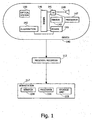
- Figure 1 is a schematic illustration of an in-vivo system according to an embodiment of the invention.
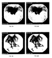
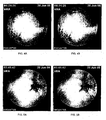
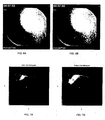
- Figures 2A-6B show various images captured by the in-vivo imaging device in both a regular, full color view (2A, 3A, 4A, 5A and 6A) and in color-stretched view (2B, 3B, 4B, 5B and 6B);
- Figure 7A shows a histogram of color coordinates of a subset of pixels of the images captured by the in-vivo imaging device
- Figure 7B shows a histogram of color coordinates of a subset of image pixels after color stretching using the methods of the invention
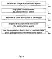
- Figure 8 is a schematic block diagram illustrating a method according to an embodiment of the invention.
- Some embodiments of the present invention are directed to an in-vivo device that may be inserted into a body lumen, e.g., the gastro-intestinal (GI) tract, for example, from outside the body. Some embodiments are directed to a typically one time use or partially single use detection and/or analysis device. Some embodiments are directed to a typically swallowable in-vivo device that may passively or actively progress through a body lumen, e.g., the gastro-intestinal (GI) tract, for example, pushed along by natural peristalsis. Some embodiments are directed to in-vivo sensing devices that may be passed through other body lumens, for example, through blood vessels, the reproductive tract, or the like.
- a body lumen e.g., the gastro-intestinal (GI) tract
- GI gastro-intestinal
- Some embodiments are directed to in-vivo sensing devices that may be passed through other body lumens, for example, through blood vessels, the reproductive tract, or the like.
- the in-vivo device may be, for example, a sensing device, an imaging device, a diagnostic device, a detection device, an analysis device, a therapeutic device, or a combination thereof.
- the in-vivo device may include an image sensor or an imager and/or other suitable components. Some embodiments of the present invention may be directed to other imaging devices, not necessarily in-vivo imaging.
- Devices, systems and methods according to some embodiments of the present invention may be similar to embodiments described in United States Patent Number 5,604,531 to Iddan et al. , entitled “In-vivo Video Camera System”, and/or in United States Patent Number 7,009,634 to Iddan et al. , entitled “Device for In-Vivo Imaging", all of which are hereby incorporated by reference in their entirety.
- Devices arid systems as described herein may have other configurations and/or sets of components.
- an external receiver/recorder unit, a processor and a monitor e.g., in a workstation, such as those described in the above publications, may be suitable for use with some embodiments of the present invention.
- Devices and systems as described herein may have other configurations and/or other sets of components.
- Some in-vivo devices may be capsule shaped, or may have other shapes, for example, a peanut shape or tubular, spherical, conical, or other suitable shapes.
- Embodiments of the present invention include, a swallowable in-vivo device. Some embodiments may be used in various body lumens, for example, the GI tract, blood vessels, the urinary tract, the reproductive tract, or the like.
- Embodiments of the in-vivo device are typically autonomous and are typically self-contained.
- the in-vivo device may be or may include a capsule or other unit where all the components are substantially contained within a container, housing or shell, and where the in-vivo device does not require any wires or cables to, for example, receive power or transmit information.
- the in-vivo device may communicate with an external receiving and display system to provide display of data, control, or other functions.
- power may be provided by an internal battery or an internal power source, or using a wired or wireless powder-receiving system.
- Other embodiments may have other configurations and capabilities.
- components may be distributed over multiple sites or units; and control information or other information may be received from an external source.
- Devices, systems and methods in accordance with some embodiments of the invention may be used, for example, in conjunction with a device which may be inserted into a human body or swallowed by a person.
- embodiments of the invention are not limited in this regard, and may be used, for example, in conjunction with a device which may be inserted into, or swallowed by, a non-human body or an animal body.
- Figure 1 schematically illustrates an in-vivo system in accordance with some embodiments of the present invention.
- One or more components of the system may be used in conjunction with, or may be operatively associated with, the devices and/or components described herein or other in-vivo devices in accordance with embodiments of the invention.
- the system may include a device 140 having a sensor, e.g., an imager 146, one or more illumination sources 142, a power source 145, and a transmitter 141.
- device 140 may be implemented using a swallowable capsule, but other sorts of devices or suitable implementations may be used.
- an external receiver/recorder 112 including, or operatively associated with, for example, one or more antennas, or an antenna array
- a storage unit 119 which may be or include for example one or more of a memory, a database, etc. or other storage systems
- processor 114, storage unit 119 and/or monitor 118 may be implemented as a workstation 117, e.g., a computer or a computing platform.
- Transmitter 141 may operate using radio waves; but in some embodiments, such as those where device 140 is or is included within an endoscope, transmitter 141 may transmit/receive data via, for example, wire, optical fiber and/or other suitable methods. Other known wireless methods of transmission may be used. Transmitter 141 may include, for example, a transmitter module or sub-unit and a receiver module or sub-unit, or an integrated transceiver or transmitter-receiver.
- Device 140 typically may be or may include an autonomous swallowable capsule, but device 140 may have other shapes and need not be swallowable or autonomous. Embodiments of device 140 are typically autonomous, and are typically self-contained. For example, device 140 may be a capsule or other unit where all the components are substantially contained within a container or shell, and where device 140 does not require any wires or cables to, for example, receive power or transmit information. In some embodiments, device 140 may be autonomous and non-remote-controllable; in another embodiment, device 140 may be partially or entirely remote-controllable.
- device 140 may communicate with an external receiving and display system (e.g., workstation 117 or monitor 118) to provide display of data, control, or other functions.
- an external receiving and display system e.g., workstation 117 or monitor 118
- power may be provided to device 140 using an internal battery, an internal power source, or a wireless system able to receive power.
- Other embodiments may have other configurations and capabilities. For example, components may be distributed over multiple sites or units, and control information or other information may be received from an external source.
- device 140 may include an in-vivo video camera, for example, imager 146, which may capture and transmit images of, for example, the GI tract while device 140 passes through the GI lumen. Other lumens and/or body cavities may be imaged and/or sensed by device 140.
- imager 146 may include, for example, a Charge Coupled Device (CCD) camera or imager, a Complementary Metal Oxide Semiconductor (CMOS) camera or imager, a digital camera, a stills camera, a video camera, or other suitable imagers, cameras, or image acquisition components.
- CCD Charge Coupled Device
- CMOS Complementary Metal Oxide Semiconductor
- imager 146 in device 140 may be operationally connected to transmitter 141.
- Transmitter 141 may transmit images to, for example, external transceiver or receiver/recorder 112 (e.g., through one or more antennas), which may send the data to processor 114 and/or to storage unit 119.
- Transmitter 141 may also include control capability, although control capability may be included in a separate component, e.g., processor 147.
- Transmitter 141 may include any suitable transmitter able to transmit image data, other sensed data, and/or other data (e.g., control data) to a receiving device.
- Transmitter 141 may also be capable of receiving signals/commands, for example from an external transceiver.
- transmitter 141 may include an ultra low power Radio Frequency (RF) high bandwidth transmitter, possibly provided in Chip Scale Package (CSP).
- RF Radio Frequency
- CSP Chip Scale Package
- transmitter 141 may transmit/receive via antenna 148.
- Transmitter 141 and/or another unit in device 140 e.g., a controller or processor 147, may include control capability, for example, one or more control modules, processing module, circuitry and/or functionality for controlling device 140, for controlling the operational mode or settings of device 140, and/or for performing control operations or processing operations within device 140.
- transmitter 141 may include a receiver which may receive signals (e.g., from outside the patient's body), for example, through antenna 148 or through a different antenna or receiving element.
- signals or data may be received by a separate receiving device in device 140.
- Power source 145 may include one or more batteries or power cells.
- power source 145 may include silver oxide batteries, lithium batteries, other suitable electrochemical cells having a high energy density, or the like. Other suitable power sources may be used.
- power source 145 may receive power or energy from an external power source (e.g., an electromagnetic field generator), which may be used to transmit power or energy to in-vivo device 140.
- an external power source e.g., an electromagnetic field generator
- power source 145 may be internal to device 140, and/or may not require coupling to an external power source, e.g., to receive power. Power source 145 may provide power to one or more components of device 140 continuously, substantially continuously, or in a non-discrete manner or timing, or in a periodic manner, an intermittent manner, or an otherwise non-continuous manner. In some embodiments, power source 145 may provide power to one or more components of device 140, for example, not necessarily upon-demand, or not necessarily upon a triggering event or an external activation or external excitement.
- transmitter 141 may include a processing unit or processor or controller, for example, to process signals and/or data generated by imager 146.
- the processing unit may be implemented using a separate component within device 140, e.g., controller or processor 147, or may be implemented as an integral part of imager 146, transmitter 141, or another component, or may not be needed.
- the processing unit may include, for example, a Central Processing Unit (CPU), a Digital Signal Processor (DSP), a microprocessor, a controller, a chip, a microchip, a controller, circuitry, an Integrated Circuit (IC), an Application-Specific Integrated Circuit (ASIC), or any other suitable multi-purpose or specific processor, controller, circuitry or circuit.
- the processing unit or controller may be embedded in or integrated with transmitter 141, and may be implemented, for example, using an ASIC.
- Processor 114 may include a processing unit, processor or controller.
- the processing unit may include, for example, a CPU, a DSP, a microprocessor, a controller, a chip, a microchip, a controller, circuitry, an IC, an ASIC, or any other suitable multi-purpose or specific processor, controller, circuitry or circuit.
- imager 146 may acquire in-vivo images continuously, substantially continuously, or in a non-discrete manner, for example, not necessarily upon-demand, or not necessarily upon a triggering event or an external activation or external excitement; or in a periodic manner, an intermittent manner, or an otherwise non-continuous manner.
- transmitter 141 may transmit image data continuously, or substantially continuously, for example, not necessarily upon-demand, or not necessarily upon a triggering event or an external activation or external excitement; or in a periodic manner, an intermittent manner, or an otherwise non-continuous manner.
- device 140 may include one or more illumination sources 142, for example one or more Light Emitting Diodes (LEDs), "white LEDs", or other suitable light sources.
- Illumination sources 142 may, for example, illuminate a body lumen or cavity being imaged and/or sensed.
- An optional optical system 150 including, for example, one or more optical elements, such as one or more lenses or composite lens assemblies, one or more suitable optical filters, or any other suitable optical elements, may optionally be included in device 140 and may aid in focusing reflected light onto imager 146, focusing illuminated light, and/or performing other light processing operations.
- device 140 may include one or more illumination sources 142 wherein the illumination sources are in a color transmission range that is narrower than "white LEDs" and may be red, yellow, blue, green, purple or orange in certain embodiments.
- the color of the illumination source is selected based on the pathology sought to be detected, using the methods described herein.
- narrowing the wavelength emitted by the illumination source 142 may assist in obtaining a better contrast using the methods described herein.
- device 140 comprises an illumination source 142 wherein the illumination source is one or more light emitting diodes, emitting light at a wavelength of between about 430 and 530 nm (Blue LED) with a peak at about 480nm, or in another embodiment a green LED emitting light at a wavelength of between about 480 and 580 nm, with a peak at about 530 nm, or in another embodiment a red LED emitting light at a wavelength of between about 580 and 680 nm, with a peak at about 630 nm.
- the illumination source is one or more light emitting diodes, emitting light at a wavelength of between about 430 and 530 nm (Blue LED) with a peak at about 480nm, or in another embodiment a green LED emitting light at a wavelength of between about 480 and 580 nm, with a peak at about 530 nm, or in another embodiment a red LED emitting light at a wavelength of between about 580 and 680 nm, with a peak
- illumination source(s) 142 may illuminate continuously, or substantially continuously, for example, not necessarily upon-demand, or not necessarily upon a triggering event or an external activation or external excitement.
- illumination source(s) 142 may illuminate a pre-defined number of times per second (e.g., two, three or four times), and operate in such a way substantially continuously, e.g., for a time period of two hours, four hours, eight hours, or the like; or in a periodic manner, an intermittent manner, or an otherwise non-continuous manner.
- the components of device 140 may be enclosed within a housing or shell, e.g., capsule-shaped, oval, or having other suitable shapes.
- the housing or shell may be substantially transparent or semi-transparent, and/or may include one or more portions, windows or domes that may be substantially transparent or semi-transparent.
- one or more illumination source(s) 142 within device 140 may illuminate a body lumen through a transparent or semi-transparent portion, window or dome; and light reflected from the body lumen may enter the device 140, for example, through the same transparent or semi-transparent portion, window or dome, or, optionally, through another transparent or semi-transparent portion, window or dome, and may be received by optical system 150 and/or imager 146.
- optical system 150 and/or imager 146 may receive light, reflected from a body lumen, through the same window or dome through which illumination source(s) 142 illuminate the body lumen.
- Data processor 114 may analyze the data received via external receiver/recorder 112 from device 140, and may be in communication with storage unit 119, e.g., transferring frame data to and from storage unit 119. Data processor 114 may provide the analyzed data to monitor 118, where a user (e.g., a physician) may view or otherwise use the data. In some embodiments, data processor 114 may be configured for real time processing and/or for post processing to be performed and/or viewed at a later time.
- control capability e.g., delay, timing, etc
- a suitable external device such as, for example, data processor 114 or external receiver/recorder 112 having a transmitter or transceiver
- Monitor 118 may include, for example, one or more screens, monitors, or suitable display units. Monitor 118, for example, may display one or more images or a stream of images captured and/or transmitted by device 140, e.g., images of the GI tract or of other imaged body lumen or cavity. Additionally or alternatively, monitor 118 may display, for example, control data, location or position data (e.g., data describing or indicating the location or the relative location of device 140), orientation data, and various other suitable data. In some embodiments, for example, both an image and its position (e.g., relative to the body lumen being imaged) or location may be presented using monitor 118 and/or may be stored using storage unit 119. Other systems and methods of storing and/or displaying collected image data and/or other data may be used.
- a physician or a health care specialist may receive a stream of in vivo images, for example captured by a swallowable capsule or by another in vivo imaging device, such as an endoscope.
- the physician may need to carefully review the image stream, for example to determine if there are any abnormalities or pathologies which may be identified in the images.
- An abnormality viewed in an image captured by a capsule without color contrast enhancement may be very similar in color to the healthy tissue around it. Therefore it may be difficult to distinguish between a healthy segment of the tissue to an abnormal segment or a pathology such as a tumor or a lesion.
- the amount of images captured by the imaging device and presented to the physician may be very large.
- An image stream captured by swallowable capsule may comprise thousands of images, for example the imaging procedure may take for example 8 hours in a constant or variable frame rate of for example 2-36 frames per second.
- the imaging procedure may take more or less time, for example depending on the patient or on the type of procedure performed.
- an adaptive frame rate of image capture may be used, for example taking one frame every 2 minutes when the capsule is not moving or when it is moving extremely slowly, and when the capsule is moving fast the imaging rate may increase for example up to 36 frames per second.
- the frame rate may be lower than 1/120 frames per second, or higher than 36 frames per second. Therefore an image stream containing thousands of images, for example 50,000 images, may be obtained.
- Abnormalities in the gastrointestinal tract such as abnormal tissue segments, tumors or other pathologies, may appear in only a few images of the stream.
- the color variation of the abnormality compared to the healthy tissue may be very slight - for example the color of the diseased tissue may be slightly more reddish than the healthy tissue. In another example, only the color of the area around the diseased tissue may have a bit darker or a bit lighter color than the healthy tissue. The color of the diseased tissue may also be different than red, for example more whitish or more bluish. Therefore it may be useful to highlight or otherwise indicate the difference for the physician between the colors of the abnormalities in comparison to the colors of the surrounding healthy tissue (for example by enhancing the color contrast of the images including the pathology as may be enabled by embodiments of the present invention). Such indication may allow a faster review of the image stream without missing or overlooking a suspected pathology area, and thereby may enable shortening the time that the physician spends reviewing the images.
- device 140 may transmit image information in discrete portions. Each portion may typically correspond to an image or a frame; other suitable transmission methods may be used. For example, in some embodiments, device 140 may capture and/or acquire an image once every half second, and may transmit the image data to external receiver/recorder 112. Other constant and/or variable capture rates and/or transmission rates may be used.
- Identifying pathologies such as tumors, lesions or ulcers and the like within images of the GI tract may be complicated by the fact that the gastrointestinal tract and the item or pathology sought to be viewed have very similar background color.
- the color of a tumor for example may be very similar to the healthy tissue around it, however a trained physician may be able to distinguish between the healthy tissue and the tumor, based for example on slight difference in the color which may be difficult to distinguish for the untrained eye.
- Abnormalities may also be distinguished in other methods, for example based on difference in shape from the normal tissue, or based on difference of texture in a healthy tissue compared to a diseased tissue.
- the colors of the original image may be expanded and changed, for example to different shades and unnatural colors, in order to provide a better contrast between healthy tissue and diseased tissue.
- a computer-implemented method for constructing a color expanded image for example an image representing an item viewed by an autonomous in vivo device.
- the color contrast of the image is enhanced by transforming the values of the original color space, for example the natural color space and expanding it in such a way that the item observed will have a higher color contrast, and in a preferred embodiment the item may have the highest color contrast possible in the available color values.
- the item may be viewed with the autonomous in vivo device, and an image is captured. Pixel characteristics of the image are mapped into a another color space. A color contrast enhancement of the image is induced with a color transformation that expands the color distribution.
- Figures 2A, 3A , 4A, 5A and 6A show various images that were captured in vivo. As can be seen in these figures (best viewed in color), the images have a reddish tint, which is due to the fact that the gastrointestinal tract itself in fact has a reddish color. It may be somewhat difficult to view pathologies such as tumors, lesions or ulcers and the like, with as much detail and clarity as would be desired, due to the fact that the pathologies have the same reddish tint that the gastrointestinal tract has.
- Figures 2B, 3B , 4B, 5B and 6B show the images after having been color-enhanced in accordance with an embodiment of the invention.
- the color-contrast of the images has been enhanced to provide a better color-contrast within the images, such that pathologies such as tumors, lesions or ulcers and the like, may be viewed with more detail and clarity.
- the enhanced colors are artificial colors, which may not represent the natural colors of the item sought to be viewed, and the borders of the item may be emphasized as a result of the color enhancement.
- use of the color transformation in the methods decribed herein comprises performing the following operations: obtaining the pixel color characteristics of the image (See Figure 7A ); transforming the original pixel color characteristics to a different color coordinate set (according to one embodiment this step may be optional); determining the mean value of the original color distribution; and correcting the pixel color characteristics based on a new mean and a scaling factor.
- the mean of the predetermined color coordinates may be computed or set for a given predetermined color wavelength range.
- the mean value of the original color distribution may be determined based on an image, or a portion of an image.
- the mean may be calculated based on a series of sequential images or on portions of the sequential images. For example, only a portion of the image, such as a circle which is centered in the center of the image, may be used for calculating the mean.
- use of the color transformation in the methods decribed herein comprises performing the following operations: obtaining the pixel color characteristics of the image; determining a new mean value of the original color distribution using a normalized RGB color space (r, g, b); and correcting the pixel color characteristics based on the new mean.
- a color is a visual sensation produced by a specific spectral power distribution incident on the retina.
- characterizing the pixel characteristic of the images captured involves calculating color response functions using a color coordinate systems referred to in another embodiment as color spaces or spectral spaces, which are means by which colors can be specified, created and visualized. Different color spaces are better for different applications.
- the methods described herein utilize color management systems (CMSs) to characterize the captured images and to transform color data between the color imaging systems.
- CMSs color management systems
- a multi-spectral image is a collection of two or more monochrome images of the same scene.
- Multi-spectral images can be described in any one of a plurality of known spectral or color spaces.
- one well-known multi-spectral image is an RGB (red-green-blue) color image.
- An RGB color image consists of a red, a green and a blue component and, thus, the image is said to be described in RGB spectral space.
- the original color coordinate system used is RGB.
- the matrix of digital data values obtained using the methods described herein is generally referred to as a "digital image” or more simply an “image” and may be stored in a digital data storage device, such as a memory, for example, as an array of numbers representing the spatial distribution of energy at different wavelengths in a scene.
- Digital multi-spectral images, as well as all digital images are represented by an array of pixels.
- Each of the numbers in the array corresponds to a digital value typically referred to as a "picture element” or a "pixel” or as “image data.”
- a pixel represents a single sample which is located at specific spatial coordinates in the image.
- each pixel being represented by a predetermined number of bits (e.g., eight bits) which represent the color red (R bits), a predetermined number of bits (e.g., eight bits) which represent the color green (G bits) and a predetermined number of bits (e.g., eight bits) which represent the color blue (B-bits).
- R bits color red
- G bits color green
- B-bits predetermined number of bits
- a pixel may be represented by a twenty-four bit sequence. It is of course possible to use greater or fewer than eight bits for each of the RGB values.
- the color space that is used is Commission Internationale de l'Eclairage L*a*b* (CIELAB) color space.
- CIELAB Commission Internationale de l'Eclairage L*a*b*
- HVS human visual system
- color pixels are represented using other color or spectral schemes such as a hue, saturation, brightness (HSB) scheme or a cyan, magenta, yellow, black (CMYK) scheme.
- the schemes used in the methods described herein are RGB, CMY (cyan, magenta, yellow), CYMK, HSI (intensity), HCI (chroma/colorfulness), TSD (hue saturation and darkness), HSV (value), or YCbCr, YUV, UVW, U'V'W', YCC and YIQ (television transmission colour spaces) coordinate set or color schemes, as well as CIE L*u*v* and CCIR (Comite Consultatif International des Radiocommunications) 601 YCbCr, spectral spaces.
- the techniques described herein are applicable to a plurality of color schemes including but not limited to the above mentioned RGB, HSB, CMYK schemes as well as the Luminosity and color axes a & b (Lab) color coordinate system, the Karhunen-Loeve color coordinate system, the retinal cone color coordinate system and the CIE X,Y,Z scheme.
- the mean of a portion of the image is then evaluated.
- the mean value of the color distribution may be determined for a given predetermined color wavelength range.
- a new mean is determined for an expanded color distribution.
- this original mean value is evaluated for each frame separately.
- this mean is evaluated in advance based on statistics of many GI images.
- the calculation of the original mean value can be based on IIR, for example taking into account history values calculated in recent or previous images in the stream.
- the scaling or expansion factor used in the methods described herein is variable and may be selected as a function based on an image region.
- An "image region" or more simply a “region” is a portion of an image. For example, if an image is provided as a 32x32 pixel array, a region may correspond to a 4x4 portion of the 32x32 pixel array. In a preferred embodiment, the pixel array is much larger, for example using an imager that is 256x256 pixels.
- the scaling factor is constant gain (for example, 2.5).
- the scaling factor may be selected or fine-tuned based on input from the user. Input from the user may be used for determining other parameters, for example the new mean value of the expanded color distribution.
- the scale factor may be changed as a function of other parameters, such as luminance (Y). For example, if the luminance is low, the scale factor may be lower than the user's selected input in order to avoid adding unnecessary noise in the image.
- a predetermined region, or area of interest (AOI) is determined using an alternative spectroscopic method, such as ultrasound in one embodiment. Accordingly, and in certain embodiment, the pixel array is adapted to yield the preferred color contrast of the area of interest, while outside the AOI, the color contrast of the pixel array may be lower, higher, and may remain unchanged.
- New_u and New_v refer to preselected values in the u' v' color space, selected as the desired mean based on which the color transformation is to be performed.
- the mean of the color distribution may be shifted to a central area in the second color space and then the color distribution may be stretched, to utilize a larger color range.
- the New_u and New_v new mean values may be selected in a central position of the second color space, in order to enable maximal expansion in all directions of the color characteristics, thereby enabling a higher or maximal color contrast of the enhanced image.
- the new mean values need not be selected in a central position, and the expansion of the color characteristics may be performed in a non-symetrical manner around the selected new mean values.
- the calculation/selection of the new mean and values may depend on the image region of interest in one embodiment, or the pathology, item, region and the like in other embodiments.
- New_u and New_v in one embodiment might be white for better visualization and separation, and in another embodiment might be the original mean of image to keep natural or original colors.
- white New_u and New_v are 0.1978, 0.4683.
- the white point is 0.333, 0.333.
- the mean in images that are substantially reddish, for example in vivo images, the mean may be placed in the gray or white area of the second color space, for example the u', v' color space.
- New_u' and New_v' are then transformed back from u' v' image values to RGB image values.
- Normalized r, g, b space may be used instead of the u' v' space.
- Correcting non plausible data may be performed by cropping negative coordinate values and coordinate values larger than 1.
- values that are not in the valid range or a predetermined range, for example 0-255 may be cropped or corrected to a predetermined valid value.
- the third component is preferably kept constant.
- Y luminance
- r g the sum of R, G, B may be kept constant.
- max (R, G, B) may also be kept fixed, instead of the sum of R, G, B.
- new pixel color values (coordinates) in the second color space may be changed until the image or the image region sought to be viewed yields the optimal color contrast.
- the user may be able to control, for example manually refine, the color contrast.
- the color contrast value may be changed as a function of the luminance, i.e., decrease the color contrast in low values of luminance in order to avoid emphasizing color noise in low intensities.
- the values of u and v are changed so that the resulting image yields an image utilizing for example the full spectrum of visible light to provide better color contrast compared to the red-tinted images of the lumen.
- optimal contrast is obtained by varying the values of New_u and New_v by the user.
- the wavelength of the illumination source 142 is adjusted to provide optimal contrast between a pathology and a background pattern associated with the pathology.
- providing optimal color contrast refers to providing maximum color contrast between an observed pathology and a background pattern associated with the pathology.
- the wavelength of the illumination source 142 is adjusted to provide optimal color contrast between a healthy structure and a corresponding pathology.
- optimal color contrast refers to varying the values of u and v in such a way as to compensate for low luminescence intensity in one embodiment, or high luminescence intensity in another embodiment.
- the expansion of the color values may be calculated without determining a new mean value.
- the color coordinate system used to transform the data to and from may be changed to optimize the observed image region or pathology viewed.
- the methods described hereinabove are used for methods of enhancing color contrast in an image region described herein.
- a method of increasing color contrast of an image or a portion of an image comprising: receiving or obtaining images and from the received images, constructing a color expanded image, wherein the color expansion enhances color contrast of the image or of a region of interest within an image.
- constructing a color expanded image for increasing color contrast of an image or a portion of an image in a gastrointestinal tract viewed by an autonomous in vivo device comprises the steps of: receiving an image in a first color space (800); mapping pixel characteristics, such as brightness and color values in certain embodiments of the image to a second color space (810) and estimating a color distribution of the image (820); expanding the color distribution over valid values of the second color space (830) to obtain a stretched/expanded distribution, and using the expanded color distribution to compute new pixel characteristics in the first color space (840).
- computing new pixel characteristics may comprise inducing a color transformation to the pixel characteristics based on the stretched distribution.
- constructing the color-expanded image comprises the operations of obtaining the pixel color characteristics; transforming the original pixel color characteristics to a different color coordinate set; for a given predetermined color wavelength range, determining a new mean value of the expanded color distribution; and determining the pixel color characteristics based on the new mean.
- the coordinate set used, or the new mean values or scaling factors in other embodiments are selected based on the pathologies sought to be imaged.
- the image analysis and/or comparison may be performed in substantially real time, for example, while device 140 is in-vivo, while imager 146 acquires images, while transmitter 141 transmits image data, while receiver/recorder 112 receives image data, and/or while workstation 117 displays in-vivo images.
- the invention provides a graphical user interface, which may be displayed on monitor 118, that provides the user with the option of viewing a selected image captured by the in-vivo imaging device in either regular view or in the color expanded or "enhanced" color view, e.g., in the full spectrum of visible colors.
- This interface allows the user to enable more distinct viewing of the selected images at will.
- the enhanced color contrast view may be applied to selected images only, for example images selected by the physician or images automatically selected by a processing unit such as processing unit 114 shown in fig. 1 . These images may be suspected of showing a pathology or an abnormality of the gastrointestinal tissue.
- the enhanced color view may be applied to all images in the image stream, or to some images, for example every second or third image, or every 100 th image. Other configurations of applying the enhanced color view may be used.
- the level of color contrast enhancement may be determined by a user, for example while viewing the image stream.
- the user may set the level of color contrast enhancement by selecting a level from a list of predetermined levels, or by moving a sliding button across a color contrast enhancement level bar, which for example may gradually change the setting of the color contrast enhancement.
- Other user interface implementations may be used.
- the enhanced image output of the contrast enhancement may be closer to the natural colors of the tissue when the level is set to a lower contrast level, and may be very different from the natural colors of the tissue (as originally images by the imager) when the level of color contrast enhancement is set to a higher level.
- Example 1 Method for Generating Blue Enhanced Gastrointestinal image
- RGB images were obtained, as shown in Figures 2A, 3A , 4A, 5A and 6A .
- the RGB values were then transformed to a second set of coordinates (u' v' color space).
- New_u ⁇ u ⁇ - u ⁇ ⁇ ScaleFactor + New_u ⁇
- New_v ⁇ v ⁇ - v ⁇ ⁇ ScaleFactor + New_v ⁇
- fixed gain on G and B channels may be applied, however pathologies for example in in-vivo images may be less noticeable.
- the R, G, B values may be corrected (for example, the values may be cropped or divided by a single predetermined or computed factor) in order to remain in the range of valid values.
- the R channel may be kept constant, since it may use a wide dynamic range in cetain configurations such as in vivo images.
- the gain on R, G and B channels may be calculated and expanded according to specific pixel characteristics. In such embodiments, a second color space need not be used, and all calculations may be performed on the original color space.
- a histogram of u' v' coordinates of a subset of pixels in the images was prepared before and after the color transformation in u'v' dimension.
- the subset of pixels may include all lighted pixels, or may include a group of pixel which matches a selection condition or criterion, for example a predetermined condition.
- Figure 7A shows the histogram of u' v' coordinates of the subset of pixels which includes all pixels in a lighted area of the images captured by the in-vivo imaging device
- Figure 7B shows the histogram of u' v' coordinates of all pixels in a lighted area of the images after color expansion using the methods of the invention.
- the histogram is very sharp, so its logarithm was plotted, normalized by the maximum. Pure colors are also plotted for reference, and the white point, which may be used as the new mean according to a preferred embodiment, is described by the "+" sign.
Landscapes
- Engineering & Computer Science (AREA)
- Health & Medical Sciences (AREA)
- Life Sciences & Earth Sciences (AREA)
- Surgery (AREA)
- Signal Processing (AREA)
- Multimedia (AREA)
- Physics & Mathematics (AREA)
- Biomedical Technology (AREA)
- Animal Behavior & Ethology (AREA)
- Pathology (AREA)
- Radiology & Medical Imaging (AREA)
- Nuclear Medicine, Radiotherapy & Molecular Imaging (AREA)
- Biophysics (AREA)
- Heart & Thoracic Surgery (AREA)
- Medical Informatics (AREA)
- Molecular Biology (AREA)
- Optics & Photonics (AREA)
- General Health & Medical Sciences (AREA)
- Public Health (AREA)
- Veterinary Medicine (AREA)
- Theoretical Computer Science (AREA)
- General Physics & Mathematics (AREA)
- Endoscopes (AREA)
- Measurement Of The Respiration, Hearing Ability, Form, And Blood Characteristics Of Living Organisms (AREA)
Claims (8)
- Procédé d'augmentation du contraste d'une image, le procédé comprenant :la réception d'une image dans un premier espace colorimétrique, l'image ayant été capturée par une capsule endoscopique comprenant un imageur pour obtenir des images de l'intérieur d'une lumière corporelle ;la mise en correspondance entre des caractéristiques de couleur de pixel de l'image et un deuxième espace colorimétrique ;l'obtention d'une distribution de couleur de l'image dans le deuxième espace colorimétrique ;la détermination d'une valeur moyenne d'origine de la distribution de couleur de l'image dans le deuxième espace colorimétrique ;la détermination d'une nouvelle valeur moyenne dans le deuxième espace colorimétrique, la nouvelle valeur moyenne étant déterminée sur la base d'une valeur prédéterminée ;le calcul de nouvelles caractéristiques de couleur de pixel dans le deuxième espace colorimétrique avec l'équation suivante :


oùu etv désignent les valeurs moyennes d'origine dans le deuxième espace colorimétrique ;New_u etNew_v désignent les nouvelles valeurs moyennes dans le deuxième espace colorimétrique ;New_u' et New_v' désignent les caractéristiques de couleur de pixel dans le deuxième espace colorimétrique ;u ' et v ' désignent les caractéristiques de couleur de pixel d'origine dans le deuxième espace colorimétrique ; etScaleFactor désigne un facteur d'échelle choisi ; etoù la luminance est maintenue constante ;etla construction d'une image à gamme étendue de couleurs dans le premier espace colorimétrique en transformant les nouvelles caractéristiques de couleur de pixel calculées dans le deuxième espace colorimétrique en nouvelles caractéristiques de couleur de pixel dans le premier espace colorimétrique. - Procédé de la revendication 1, dans lequel la valeur prédéterminée est le point blanc.
- Procédé de la revendication 1 ou 2, dans lequel la valeur moyenne d'origine est déterminée sur la base : de l'image, d'un sous-ensemble de pixels choisis dans l'image ou d'images précédentes dans un flux d'images.
- Procédé de l'une des revendications précédentes, dans lequel le premier espace colorimétrique est un espace colorimétrique RGB.
- Procédé de la revendication 4, moyennant quoi le deuxième espace colorimétrique est un espace colorimétrique normalisé RGB, CYM, CYMK, HIS, HSV, YCbCr, YUV, UVW, U'V'W', CIE ou YIQ.
- Procédé de l'une des revendications précédentes, dans lequel le facteur d'échelle est choisi sur la base d'une entrée d'utilisateur.
- Procédé de l'une des revendications précédentes, comprenant en outre la correction des caractéristiques de couleur de pixel non plausibles.
- Système d'augmentation du contraste d'une image, le système comprenant :une capsule endoscopique comprenant un imageur pour obtenir des images de l'intérieur d'une lumière corporelle ;un moyen destiné à recevoir une image capturée par ladite capsule endoscopique dans un premier espace colorimétrique ;un moyen destiné à mettre en correspondance des caractéristiques de couleur de pixel de l'image avec un deuxième espace colorimétrique ;un moyen destiné à obtenir une distribution de couleur de l'image dans le deuxième espace colorimétrique ;un moyen destiné à déterminer une valeur moyenne d'origine de la distribution de couleur de l'image dans le deuxième espace colorimétrique ;un moyen destiné à déterminer une nouvelle valeur moyenne pour une distribution de couleur étendue dans le deuxième espace colorimétrique, la nouvelle valeur moyenne étant déterminée sur la base d'une valeur prédéterminée ;un moyen destiné à calculer de nouvelles caractéristiques de couleur de pixel dans le deuxième espace colorimétrique avec l'équation suivante :


oùu etv désignent les valeurs moyennes d'origine dans le deuxième espace colorimétrique ;New_u etNew_v désignent les nouvelles valeurs moyennes dans le deuxième espace colorimétrique ;New_u' et New_v' désignent les nouvelles caractéristiques de couleur de pixel dans le deuxième espace colorimétrique ;u ' et v ' désignent les caractéristiques de couleur de pixel d'origine dans le deuxième espace colorimétrique ; etScaleFactor désigne un facteur d'échelle choisi ; etoù la luminance est maintenue constante ;etun moyen destiné à construire une image à gamme étendue de couleurs dans le premier espace colorimétrique sur la base des nouvelles caractéristiques de couleur de pixel calculées dans le deuxième espace colorimétrique.
Applications Claiming Priority (1)
| Application Number | Priority Date | Filing Date | Title |
|---|---|---|---|
| US2169608P | 2008-02-26 | 2008-02-26 |
Publications (3)
| Publication Number | Publication Date |
|---|---|
| EP2096859A2 EP2096859A2 (fr) | 2009-09-02 |
| EP2096859A3 EP2096859A3 (fr) | 2010-04-21 |
| EP2096859B1 true EP2096859B1 (fr) | 2015-04-22 |
Family
ID=40578039
Family Applications (1)
| Application Number | Title | Priority Date | Filing Date |
|---|---|---|---|
| EP20090002747 Active EP2096859B1 (fr) | 2008-02-26 | 2009-02-26 | Procédé d'amélioration de contraste d'image in vivo |
Country Status (3)
| Country | Link |
|---|---|
| US (1) | US8467603B2 (fr) |
| EP (1) | EP2096859B1 (fr) |
| JP (1) | JP5594711B2 (fr) |
Families Citing this family (16)
| Publication number | Priority date | Publication date | Assignee | Title |
|---|---|---|---|---|
| US8706184B2 (en) * | 2009-10-07 | 2014-04-22 | Intuitive Surgical Operations, Inc. | Methods and apparatus for displaying enhanced imaging data on a clinical image |
| JP5642373B2 (ja) * | 2009-10-23 | 2014-12-17 | オリンパス株式会社 | 携帯無線端末、無線通信システムおよび携帯無線端末の無線通信方法 |
| US8712151B2 (en) * | 2011-02-14 | 2014-04-29 | Intuitive Surgical Operations, Inc. | Method and structure for image local contrast enhancement |
| US20150049177A1 (en) * | 2012-02-06 | 2015-02-19 | Biooptico Ab | Camera Arrangement and Image Processing Method for Quantifying Tissue Structure and Degeneration |
| JP6027803B2 (ja) * | 2012-07-17 | 2016-11-16 | Hoya株式会社 | 画像処理装置及び内視鏡装置 |
| JP6067264B2 (ja) | 2012-07-17 | 2017-01-25 | Hoya株式会社 | 画像処理装置及び内視鏡装置 |
| KR101736468B1 (ko) * | 2012-12-24 | 2017-05-29 | 한화테크윈 주식회사 | 영상 처리 장치 및 방법 |
| KR101509568B1 (ko) * | 2013-06-28 | 2015-04-08 | (주)실리콘화일 | 알지비 데이터를 이용한 색보정 방법 |
| JP5985084B2 (ja) * | 2014-06-19 | 2016-09-06 | オリンパス株式会社 | 内視鏡プロセッサ |
| US9599436B2 (en) * | 2014-09-04 | 2017-03-21 | Selex Es S.P.A. | External vision and/or weapon aiming and firing system for military land vehicles, military aircraft and military naval units |
| WO2016098139A1 (fr) * | 2014-12-16 | 2016-06-23 | オリンパス株式会社 | Dispositif d'observation à balayage laser |
| WO2017026540A1 (fr) | 2015-08-13 | 2017-02-16 | Hoya株式会社 | Dispositif de calcul de valeur d'évaluation et système d'endoscope électronique |
| WO2017026539A1 (fr) | 2015-08-13 | 2017-02-16 | Hoya株式会社 | Dispositif de calcul de valeur d'évaluation et système d'endoscope électronique |
| CN109191432B (zh) * | 2018-07-27 | 2021-11-30 | 西安电子科技大学 | 基于域变换滤波多尺度分解的遥感图像云检测方法 |
| CN109767395A (zh) * | 2018-12-29 | 2019-05-17 | 深圳市资福医疗技术有限公司 | 一种胶囊内窥镜图像处理方法及装置 |
| DE102019134799B3 (de) * | 2019-12-17 | 2021-03-25 | Schölly Fiberoptic GmbH | Bildaufnahmeverfahren unter Verwendung einer Farbtransformation sowie zugehöriges medizinisches Bildaufnahmesystem |
Citations (1)
| Publication number | Priority date | Publication date | Assignee | Title |
|---|---|---|---|---|
| EP1206123A2 (fr) * | 2000-11-12 | 2002-05-15 | Thomas Dipl.-Ing. Maier | Procédé de saisie de signaux d'image |
Family Cites Families (7)
| Publication number | Priority date | Publication date | Assignee | Title |
|---|---|---|---|---|
| IL108352A (en) * | 1994-01-17 | 2000-02-29 | Given Imaging Ltd | In vivo video camera system |
| US5883984A (en) * | 1996-10-03 | 1999-03-16 | Silicon Integrated Systems Corp. | Method and apparatus for contrast enhancement of color images |
| US6393148B1 (en) | 1999-05-13 | 2002-05-21 | Hewlett-Packard Company | Contrast enhancement of an image using luminance and RGB statistical metrics |
| JP4619608B2 (ja) * | 2000-03-08 | 2011-01-26 | ギブン イメージング リミテッド | インビボ撮像のための装置およびシステム |
| CA2365893A1 (fr) * | 2001-12-21 | 2003-06-21 | Jaldi Semiconductor Corp. | Systeme et methode permettant de rehausser la qualite dynamique de l'espace chromatique |
| BRPI0302384B1 (pt) * | 2002-07-20 | 2018-06-19 | Samsung Electronics Co., Ltd. | "método para intensificar de forma adaptativa uma cor, e equipamento para intensificar de forma adaptativa a cor de uma imagem" |
| US7428332B2 (en) * | 2004-01-14 | 2008-09-23 | Spaulding Kevin E | Applying an adjusted image enhancement algorithm to a digital image |
-
2009
- 2009-02-26 US US12/393,407 patent/US8467603B2/en active Active
- 2009-02-26 JP JP2009044295A patent/JP5594711B2/ja active Active
- 2009-02-26 EP EP20090002747 patent/EP2096859B1/fr active Active
Patent Citations (1)
| Publication number | Priority date | Publication date | Assignee | Title |
|---|---|---|---|---|
| EP1206123A2 (fr) * | 2000-11-12 | 2002-05-15 | Thomas Dipl.-Ing. Maier | Procédé de saisie de signaux d'image |
Also Published As
| Publication number | Publication date |
|---|---|
| US8467603B2 (en) | 2013-06-18 |
| JP5594711B2 (ja) | 2014-09-24 |
| JP2009201994A (ja) | 2009-09-10 |
| EP2096859A3 (fr) | 2010-04-21 |
| US20090214111A1 (en) | 2009-08-27 |
| EP2096859A2 (fr) | 2009-09-02 |
Similar Documents
| Publication | Publication Date | Title |
|---|---|---|
| EP2096859B1 (fr) | Procédé d'amélioration de contraste d'image in vivo | |
| US20250235078A1 (en) | Medical image processing apparatus, endoscope system, and medical image processing method | |
| US11563921B2 (en) | Image processing apparatus, endoscope system, and image processing method | |
| US20210076917A1 (en) | Image processing apparatus, endoscope system, and image processing method | |
| US12106394B2 (en) | Medical image processing apparatus, processor device, endoscope system, medical image processing method, and program | |
| US8055033B2 (en) | Medical image processing apparatus, luminal image processing apparatus, luminal image processing method, and programs for the same | |
| CN103533878B (zh) | 医疗设备 | |
| EP1161919A2 (fr) | Méthode d'affichage d'image de sujets éclairés par de la lumière fluorescente et appareil correspondant | |
| JP2019081044A (ja) | 画像処理装置、画像処理装置の作動方法、および画像処理プログラム | |
| US9414739B2 (en) | Imaging apparatus for controlling fluorescence imaging in divided imaging surface | |
| CN113453607B (zh) | 医用图像处理装置及方法 | |
| CN112770662A (zh) | 医用图像处理装置、医用图像处理方法、及程序、诊断辅助装置以及内窥镜系统 | |
| CN105212885B (zh) | 医用图像处理装置及其工作方法、以及内窥镜系统 | |
| CN112689469A (zh) | 内窥镜装置、内窥镜处理器及内窥镜装置的操作方法 | |
| EP3318175A1 (fr) | Appareil de traitement d'images et système d'imagerie | |
| JP2002172082A (ja) | 蛍光画像表示方法および装置 | |
| US10574934B2 (en) | Ultrasound observation device, operation method of image signal processing apparatus, image signal processing method, and computer-readable recording medium | |
| US10694100B2 (en) | Image processing apparatus, image processing method, and computer readable recording medium | |
| CN214231268U (zh) | 内窥镜成像装置和电子设备 | |
| CN102186401A (zh) | 图像生成装置、内窥镜系统以及图像生成方法 | |
| JP2020078647A (ja) | 画像処理装置、画像処理装置の作動方法、および画像処理プログラム | |
| US10863149B2 (en) | Image processing apparatus, image processing method, and computer readable recording medium | |
| WO2018150627A1 (fr) | Dispositif de traitement d'image, procédé de traitement d'image et programme de traitement d'image | |
| JP6669539B2 (ja) | 画像処理装置、画像処理装置の作動方法、および画像処理プログラム | |
| EP2334084A1 (fr) | Dispositif et système de capture d'image |
Legal Events
| Date | Code | Title | Description |
|---|---|---|---|
| PUAI | Public reference made under article 153(3) epc to a published international application that has entered the european phase |
Free format text: ORIGINAL CODE: 0009012 |
|
| 17P | Request for examination filed |
Effective date: 20090226 |
|
| AK | Designated contracting states |
Kind code of ref document: A2 Designated state(s): AT BE BG CH CY CZ DE DK EE ES FI FR GB GR HR HU IE IS IT LI LT LU LV MC MK MT NL NO PL PT RO SE SI SK TR |
|
| AX | Request for extension of the european patent |
Extension state: AL BA RS |
|
| PUAL | Search report despatched |
Free format text: ORIGINAL CODE: 0009013 |
|
| AK | Designated contracting states |
Kind code of ref document: A3 Designated state(s): AT BE BG CH CY CZ DE DK EE ES FI FR GB GR HR HU IE IS IT LI LT LU LV MC MK MT NL NO PL PT RO SE SI SK TR |
|
| AX | Request for extension of the european patent |
Extension state: AL BA RS |
|
| AKX | Designation fees paid |
Designated state(s): AT BE BG CH CY CZ DE DK EE ES FI FR GB GR HR HU IE IS IT LI LT LU LV MC MK MT NL NO PL PT RO SE SI SK TR |
|
| 17Q | First examination report despatched |
Effective date: 20110502 |
|
| RIC1 | Information provided on ipc code assigned before grant |
Ipc: H04N 1/60 20060101AFI20140925BHEP Ipc: A61B 1/00 20060101ALN20140925BHEP |
|
| GRAP | Despatch of communication of intention to grant a patent |
Free format text: ORIGINAL CODE: EPIDOSNIGR1 |
|
| GRAS | Grant fee paid |
Free format text: ORIGINAL CODE: EPIDOSNIGR3 |
|
| INTG | Intention to grant announced |
Effective date: 20150216 |
|
| GRAA | (expected) grant |
Free format text: ORIGINAL CODE: 0009210 |
|
| AK | Designated contracting states |
Kind code of ref document: B1 Designated state(s): AT BE BG CH CY CZ DE DK EE ES FI FR GB GR HR HU IE IS IT LI LT LU LV MC MK MT NL NO PL PT RO SE SI SK TR |
|
| REG | Reference to a national code |
Ref country code: GB Ref legal event code: FG4D |
|
| REG | Reference to a national code |
Ref country code: CH Ref legal event code: EP |
|
| REG | Reference to a national code |
Ref country code: AT Ref legal event code: REF Ref document number: 723832 Country of ref document: AT Kind code of ref document: T Effective date: 20150515 |
|
| REG | Reference to a national code |
Ref country code: IE Ref legal event code: FG4D |
|
| REG | Reference to a national code |
Ref country code: DE Ref legal event code: R096 Ref document number: 602009030746 Country of ref document: DE Effective date: 20150603 |
|
| REG | Reference to a national code |
Ref country code: NL Ref legal event code: VDEP Effective date: 20150422 |
|
| REG | Reference to a national code |
Ref country code: AT Ref legal event code: MK05 Ref document number: 723832 Country of ref document: AT Kind code of ref document: T Effective date: 20150422 |
|
| REG | Reference to a national code |
Ref country code: LT Ref legal event code: MG4D |
|
| PG25 | Lapsed in a contracting state [announced via postgrant information from national office to epo] |
Ref country code: NL Free format text: LAPSE BECAUSE OF FAILURE TO SUBMIT A TRANSLATION OF THE DESCRIPTION OR TO PAY THE FEE WITHIN THE PRESCRIBED TIME-LIMIT Effective date: 20150422 |
|
| PG25 | Lapsed in a contracting state [announced via postgrant information from national office to epo] |
Ref country code: PT Free format text: LAPSE BECAUSE OF FAILURE TO SUBMIT A TRANSLATION OF THE DESCRIPTION OR TO PAY THE FEE WITHIN THE PRESCRIBED TIME-LIMIT Effective date: 20150824 Ref country code: ES Free format text: LAPSE BECAUSE OF FAILURE TO SUBMIT A TRANSLATION OF THE DESCRIPTION OR TO PAY THE FEE WITHIN THE PRESCRIBED TIME-LIMIT Effective date: 20150422 Ref country code: LT Free format text: LAPSE BECAUSE OF FAILURE TO SUBMIT A TRANSLATION OF THE DESCRIPTION OR TO PAY THE FEE WITHIN THE PRESCRIBED TIME-LIMIT Effective date: 20150422 Ref country code: HR Free format text: LAPSE BECAUSE OF FAILURE TO SUBMIT A TRANSLATION OF THE DESCRIPTION OR TO PAY THE FEE WITHIN THE PRESCRIBED TIME-LIMIT Effective date: 20150422 Ref country code: FI Free format text: LAPSE BECAUSE OF FAILURE TO SUBMIT A TRANSLATION OF THE DESCRIPTION OR TO PAY THE FEE WITHIN THE PRESCRIBED TIME-LIMIT Effective date: 20150422 Ref country code: NO Free format text: LAPSE BECAUSE OF FAILURE TO SUBMIT A TRANSLATION OF THE DESCRIPTION OR TO PAY THE FEE WITHIN THE PRESCRIBED TIME-LIMIT Effective date: 20150722 |
|
| PG25 | Lapsed in a contracting state [announced via postgrant information from national office to epo] |
Ref country code: AT Free format text: LAPSE BECAUSE OF FAILURE TO SUBMIT A TRANSLATION OF THE DESCRIPTION OR TO PAY THE FEE WITHIN THE PRESCRIBED TIME-LIMIT Effective date: 20150422 Ref country code: GR Free format text: LAPSE BECAUSE OF FAILURE TO SUBMIT A TRANSLATION OF THE DESCRIPTION OR TO PAY THE FEE WITHIN THE PRESCRIBED TIME-LIMIT Effective date: 20150723 Ref country code: IS Free format text: LAPSE BECAUSE OF FAILURE TO SUBMIT A TRANSLATION OF THE DESCRIPTION OR TO PAY THE FEE WITHIN THE PRESCRIBED TIME-LIMIT Effective date: 20150822 Ref country code: LV Free format text: LAPSE BECAUSE OF FAILURE TO SUBMIT A TRANSLATION OF THE DESCRIPTION OR TO PAY THE FEE WITHIN THE PRESCRIBED TIME-LIMIT Effective date: 20150422 |
|
| REG | Reference to a national code |
Ref country code: FR Ref legal event code: PLFP Year of fee payment: 8 |
|
| REG | Reference to a national code |
Ref country code: DE Ref legal event code: R097 Ref document number: 602009030746 Country of ref document: DE |
|
| PG25 | Lapsed in a contracting state [announced via postgrant information from national office to epo] |
Ref country code: EE Free format text: LAPSE BECAUSE OF FAILURE TO SUBMIT A TRANSLATION OF THE DESCRIPTION OR TO PAY THE FEE WITHIN THE PRESCRIBED TIME-LIMIT Effective date: 20150422 Ref country code: DK Free format text: LAPSE BECAUSE OF FAILURE TO SUBMIT A TRANSLATION OF THE DESCRIPTION OR TO PAY THE FEE WITHIN THE PRESCRIBED TIME-LIMIT Effective date: 20150422 |
|
| PLBE | No opposition filed within time limit |
Free format text: ORIGINAL CODE: 0009261 |
|
| STAA | Information on the status of an ep patent application or granted ep patent |
Free format text: STATUS: NO OPPOSITION FILED WITHIN TIME LIMIT |
|
| PG25 | Lapsed in a contracting state [announced via postgrant information from national office to epo] |
Ref country code: SK Free format text: LAPSE BECAUSE OF FAILURE TO SUBMIT A TRANSLATION OF THE DESCRIPTION OR TO PAY THE FEE WITHIN THE PRESCRIBED TIME-LIMIT Effective date: 20150422 Ref country code: RO Free format text: LAPSE BECAUSE OF NON-PAYMENT OF DUE FEES Effective date: 20150422 Ref country code: CZ Free format text: LAPSE BECAUSE OF FAILURE TO SUBMIT A TRANSLATION OF THE DESCRIPTION OR TO PAY THE FEE WITHIN THE PRESCRIBED TIME-LIMIT Effective date: 20150422 Ref country code: PL Free format text: LAPSE BECAUSE OF FAILURE TO SUBMIT A TRANSLATION OF THE DESCRIPTION OR TO PAY THE FEE WITHIN THE PRESCRIBED TIME-LIMIT Effective date: 20150422 |
|
| 26N | No opposition filed |
Effective date: 20160125 |
|
| PG25 | Lapsed in a contracting state [announced via postgrant information from national office to epo] |
Ref country code: IT Free format text: LAPSE BECAUSE OF FAILURE TO SUBMIT A TRANSLATION OF THE DESCRIPTION OR TO PAY THE FEE WITHIN THE PRESCRIBED TIME-LIMIT Effective date: 20150422 |
|
| PG25 | Lapsed in a contracting state [announced via postgrant information from national office to epo] |
Ref country code: SI Free format text: LAPSE BECAUSE OF FAILURE TO SUBMIT A TRANSLATION OF THE DESCRIPTION OR TO PAY THE FEE WITHIN THE PRESCRIBED TIME-LIMIT Effective date: 20150422 Ref country code: BE Free format text: LAPSE BECAUSE OF NON-PAYMENT OF DUE FEES Effective date: 20160229 |
|
| PG25 | Lapsed in a contracting state [announced via postgrant information from national office to epo] |
Ref country code: BE Free format text: LAPSE BECAUSE OF FAILURE TO SUBMIT A TRANSLATION OF THE DESCRIPTION OR TO PAY THE FEE WITHIN THE PRESCRIBED TIME-LIMIT Effective date: 20150422 |
|
| PG25 | Lapsed in a contracting state [announced via postgrant information from national office to epo] |
Ref country code: MC Free format text: LAPSE BECAUSE OF FAILURE TO SUBMIT A TRANSLATION OF THE DESCRIPTION OR TO PAY THE FEE WITHIN THE PRESCRIBED TIME-LIMIT Effective date: 20150422 Ref country code: LU Free format text: LAPSE BECAUSE OF FAILURE TO SUBMIT A TRANSLATION OF THE DESCRIPTION OR TO PAY THE FEE WITHIN THE PRESCRIBED TIME-LIMIT Effective date: 20160226 |
|
| REG | Reference to a national code |
Ref country code: CH Ref legal event code: PL |
|
| PG25 | Lapsed in a contracting state [announced via postgrant information from national office to epo] |
Ref country code: CH Free format text: LAPSE BECAUSE OF NON-PAYMENT OF DUE FEES Effective date: 20160229 Ref country code: LI Free format text: LAPSE BECAUSE OF NON-PAYMENT OF DUE FEES Effective date: 20160229 |
|
| REG | Reference to a national code |
Ref country code: IE Ref legal event code: MM4A |
|
| REG | Reference to a national code |
Ref country code: FR Ref legal event code: PLFP Year of fee payment: 9 |
|
| PG25 | Lapsed in a contracting state [announced via postgrant information from national office to epo] |
Ref country code: IE Free format text: LAPSE BECAUSE OF NON-PAYMENT OF DUE FEES Effective date: 20160226 |
|
| PG25 | Lapsed in a contracting state [announced via postgrant information from national office to epo] |
Ref country code: SE Free format text: LAPSE BECAUSE OF FAILURE TO SUBMIT A TRANSLATION OF THE DESCRIPTION OR TO PAY THE FEE WITHIN THE PRESCRIBED TIME-LIMIT Effective date: 20150422 |
|
| PG25 | Lapsed in a contracting state [announced via postgrant information from national office to epo] |
Ref country code: MT Free format text: LAPSE BECAUSE OF FAILURE TO SUBMIT A TRANSLATION OF THE DESCRIPTION OR TO PAY THE FEE WITHIN THE PRESCRIBED TIME-LIMIT Effective date: 20150422 |
|
| REG | Reference to a national code |
Ref country code: FR Ref legal event code: PLFP Year of fee payment: 10 |
|
| PG25 | Lapsed in a contracting state [announced via postgrant information from national office to epo] |
Ref country code: HU Free format text: LAPSE BECAUSE OF FAILURE TO SUBMIT A TRANSLATION OF THE DESCRIPTION OR TO PAY THE FEE WITHIN THE PRESCRIBED TIME-LIMIT; INVALID AB INITIO Effective date: 20090226 Ref country code: CY Free format text: LAPSE BECAUSE OF FAILURE TO SUBMIT A TRANSLATION OF THE DESCRIPTION OR TO PAY THE FEE WITHIN THE PRESCRIBED TIME-LIMIT Effective date: 20150422 |
|
| PG25 | Lapsed in a contracting state [announced via postgrant information from national office to epo] |
Ref country code: MT Free format text: LAPSE BECAUSE OF FAILURE TO SUBMIT A TRANSLATION OF THE DESCRIPTION OR TO PAY THE FEE WITHIN THE PRESCRIBED TIME-LIMIT Effective date: 20160229 Ref country code: MK Free format text: LAPSE BECAUSE OF FAILURE TO SUBMIT A TRANSLATION OF THE DESCRIPTION OR TO PAY THE FEE WITHIN THE PRESCRIBED TIME-LIMIT Effective date: 20150422 Ref country code: TR Free format text: LAPSE BECAUSE OF FAILURE TO SUBMIT A TRANSLATION OF THE DESCRIPTION OR TO PAY THE FEE WITHIN THE PRESCRIBED TIME-LIMIT Effective date: 20150422 |
|
| PG25 | Lapsed in a contracting state [announced via postgrant information from national office to epo] |
Ref country code: BG Free format text: LAPSE BECAUSE OF FAILURE TO SUBMIT A TRANSLATION OF THE DESCRIPTION OR TO PAY THE FEE WITHIN THE PRESCRIBED TIME-LIMIT Effective date: 20150422 |
|
| PGFP | Annual fee paid to national office [announced via postgrant information from national office to epo] |
Ref country code: DE Payment date: 20250122 Year of fee payment: 17 |
|
| PGFP | Annual fee paid to national office [announced via postgrant information from national office to epo] |
Ref country code: FR Payment date: 20250122 Year of fee payment: 17 |
|
| PGFP | Annual fee paid to national office [announced via postgrant information from national office to epo] |
Ref country code: GB Payment date: 20250123 Year of fee payment: 17 |