EP2096903A1 - Dispositif de commande de diodes électroluminescentes, dispositif d'éclairage et dispositif d'affichage - Google Patents
Dispositif de commande de diodes électroluminescentes, dispositif d'éclairage et dispositif d'affichage Download PDFInfo
- Publication number
- EP2096903A1 EP2096903A1 EP07830072A EP07830072A EP2096903A1 EP 2096903 A1 EP2096903 A1 EP 2096903A1 EP 07830072 A EP07830072 A EP 07830072A EP 07830072 A EP07830072 A EP 07830072A EP 2096903 A1 EP2096903 A1 EP 2096903A1
- Authority
- EP
- European Patent Office
- Prior art keywords
- led
- driving device
- leds
- light
- current
- Prior art date
- Legal status (The legal status is an assumption and is not a legal conclusion. Google has not performed a legal analysis and makes no representation as to the accuracy of the status listed.)
- Withdrawn
Links
Images





Classifications
-
- G—PHYSICS
- G09—EDUCATION; CRYPTOGRAPHY; DISPLAY; ADVERTISING; SEALS
- G09G—ARRANGEMENTS OR CIRCUITS FOR CONTROL OF INDICATING DEVICES USING STATIC MEANS TO PRESENT VARIABLE INFORMATION
- G09G3/00—Control arrangements or circuits, of interest only in connection with visual indicators other than cathode-ray tubes
- G09G3/20—Control arrangements or circuits, of interest only in connection with visual indicators other than cathode-ray tubes for presentation of an assembly of a number of characters, e.g. a page, by composing the assembly by combination of individual elements arranged in a matrix no fixed position being assigned to or needed to be assigned to the individual characters or partial characters
- G09G3/34—Control arrangements or circuits, of interest only in connection with visual indicators other than cathode-ray tubes for presentation of an assembly of a number of characters, e.g. a page, by composing the assembly by combination of individual elements arranged in a matrix no fixed position being assigned to or needed to be assigned to the individual characters or partial characters by control of light from an independent source
- G09G3/3406—Control of illumination source
-
- H—ELECTRICITY
- H05—ELECTRIC TECHNIQUES NOT OTHERWISE PROVIDED FOR
- H05B—ELECTRIC HEATING; ELECTRIC LIGHT SOURCES NOT OTHERWISE PROVIDED FOR; CIRCUIT ARRANGEMENTS FOR ELECTRIC LIGHT SOURCES, IN GENERAL
- H05B45/00—Circuit arrangements for operating light-emitting diodes [LED]
- H05B45/20—Controlling the colour of the light
-
- H—ELECTRICITY
- H05—ELECTRIC TECHNIQUES NOT OTHERWISE PROVIDED FOR
- H05B—ELECTRIC HEATING; ELECTRIC LIGHT SOURCES NOT OTHERWISE PROVIDED FOR; CIRCUIT ARRANGEMENTS FOR ELECTRIC LIGHT SOURCES, IN GENERAL
- H05B45/00—Circuit arrangements for operating light-emitting diodes [LED]
- H05B45/30—Driver circuits
- H05B45/37—Converter circuits
-
- G—PHYSICS
- G09—EDUCATION; CRYPTOGRAPHY; DISPLAY; ADVERTISING; SEALS
- G09G—ARRANGEMENTS OR CIRCUITS FOR CONTROL OF INDICATING DEVICES USING STATIC MEANS TO PRESENT VARIABLE INFORMATION
- G09G2310/00—Command of the display device
- G09G2310/02—Addressing, scanning or driving the display screen or processing steps related thereto
- G09G2310/0235—Field-sequential colour display
-
- G—PHYSICS
- G09—EDUCATION; CRYPTOGRAPHY; DISPLAY; ADVERTISING; SEALS
- G09G—ARRANGEMENTS OR CIRCUITS FOR CONTROL OF INDICATING DEVICES USING STATIC MEANS TO PRESENT VARIABLE INFORMATION
- G09G2320/00—Control of display operating conditions
- G09G2320/06—Adjustment of display parameters
- G09G2320/0626—Adjustment of display parameters for control of overall brightness
- G09G2320/0633—Adjustment of display parameters for control of overall brightness by amplitude modulation of the brightness of the illumination source
-
- G—PHYSICS
- G09—EDUCATION; CRYPTOGRAPHY; DISPLAY; ADVERTISING; SEALS
- G09G—ARRANGEMENTS OR CIRCUITS FOR CONTROL OF INDICATING DEVICES USING STATIC MEANS TO PRESENT VARIABLE INFORMATION
- G09G2320/00—Control of display operating conditions
- G09G2320/06—Adjustment of display parameters
- G09G2320/0626—Adjustment of display parameters for control of overall brightness
- G09G2320/064—Adjustment of display parameters for control of overall brightness by time modulation of the brightness of the illumination source
Definitions
- the present invention relates to an LED (Light Emitting Diode) driving device, an illuminating device using an LED as its light source, and a projection-type display device.
- LED Light Emitting Diode
- a field-sequential display device is an example of projection-type display devices, and forms a color image by time-divisionally displaying R (red), G (green), B (blue).
- the formation of a color image in an exemplar DLP (Digital Light Processing) projector is performed by: employing a high-pressure mercury lamp or the like as a light source; separating the white light from the light source into colors by means of a color wheel; modulating the color-separated light by means of a reflective device such as a DMD (Digital Micromirror Device); and then projecting the modulated light on a screen through a projection optical system.
- the quantization noise causes a problem in low-intensity display of the brightness expression implemented by a display device with such a reflective device.
- a conventional display device employing a lamp such as a high-pressure mercury lamp is equipped with an ND (Neutral Density) filter attached to the segments of the color wheel.
- the ND filter is designed to lower the intensity down to approximately 10% so that the apparent bits in low-intensity display can be increased and thus the quantization noise can be reduced.
- RGB LEDs emit light in a time-dividing manner, and the light thus emitted enters a reflective device to be modulated. The resultant light is then projected on a screen though a projection optical system to form a color image. Note that, in this case, the light emission for each LED is turned on and off by pulsing.
- liquid-crystal displays are examples of direct-view display devices.
- the light source of the liquid-crystal display has come to employ solid-state illumination (i.e., LEDs) in place of fluorescent tubes.
- An improvement in the performance of the liquid-crystal display has been achieved by a technique (known as an area-active technique).
- the intensities of the multiple LEDs that the liquid-crystal display device is equipped with are changed for such groups of LEDs as determined in accordance with the video image to be displayed by the liquid-crystal display device.
- the visual dynamic range is thus changed resulting in the above-mentioned improvement in the performance.
- the display device equipped with LED light source also has the problem of quantization noise at low-intensity display. Being provided with no color wheel, the kind of countermeasures such as the ND filter employed in the conventional display device with the lamp light source cannot be taken in the case of the display device with the LED light source.
- the same effect as that obtainable by use of the ND filter can be obtained by reducing the amount of the light emitted from each LED.
- the reduction in the light-emitting amounts of the LEDs can be achieved, for example, by pulse-based light modulation.
- the light emission of each LED is controlled by pulsing in a field-sequential display device, so that the pulse-based light modulation is not operable.
- Reducing the current that flows through the LEDs is another way of achieving the reduction in the amount of light emitted from each LED.
- lowering the power is a problem.
- the detected current is converted to a voltage and the resultant voltage is used for feedback in this type of modulation.
- a small current results in a small feedback voltage, which makes the light modulation control difficult.
- Patent Document 1 discloses a light-emitting diode driving device that employs a technique based on a switching circuit.
- the disclosed device employs a current-detection method based on the control using a single resistor, and cannot deal with a minute current.
- the configuration of the circuit may have a problem caused by the offset in the comparator.
- Patent Document 2 discloses a light-emitting element driving circuit that is configured to improve the efficiency by means of peak-value detection.
- the disclosed circuit is not suitable for constant current regulation from a large current to a minute current.
- Patent Document 3 also discloses a light-emitting diode driving device that employs a technique based on a switching circuit.
- the disclosed device employs a current-detection method based on the control using a single resistor, and cannot deal with a minute current.
- the configuration of the circuit may have a problem caused by the offset in the comparator.
- Patent Document 4 discloses a light-emitting diode driving device that employs a light modulation method based on switching, and thus cannot be used in the field-sequential display device. In addition, the switching makes the influence of the noise more likely to be produced.
- the present invention provides an LED driving device with the following features.
- the LED driving device if employed in a projection-type display device, is capable of stably reducing the brightness of the LEDs down to such a level that the same effect as in a case of using the ND filter can be obtained.
- the LED driving device if employed in a direct-view type display device, is capable of driving the display device by the area-active technique based not on the pulse-based light modulation control but on the current-based light modulation control.
- the present invention also provides an illuminating device and a display device each of which employs the LED light source with the above-mentioned features and which thereby reduces the generation of the noise.
- the present invention provides an LED driving device including: a driving voltage switching means for switching between a first driving voltage and a second driving voltage in accordance with a timing signal; and a feedback circuit to which any one of the first and second driving voltages is applied and which thereby determines a current flowing through an LED.
- the feedback circuit includes a current controlling means for controlling, in accordance with the timing signal, a current flowing through the LED.
- the current controlling means may be a resistor switching means for switching, in accordance with the timing signal, between opposings that determine the current flowing through the LED.
- the present invention provides an illuminating device including: an LED driving device such as one described above; and an LED driven by the LED driving device.
- the present invention provides a display device including: an LED driving device such as one described above; a green LED driven by the LED driving device; a red LED; a blue LED; a controlling means for switching between the green LED, the red LED, and the blue LED and making the selected one of the LEDs emit light; a reflective device which is controlled by the controlling means in synchronization with the light emission of the green LED, the red LED, and the blue LED, and which modulates the light emitted by the green LED, the red LED, and the blue RGB; and a projection optical system which projects light reflected by the reflective device.
- the present invention provides a direct-view type display device including an LED driving device such as one described above; and a backlighting system that can achieve an area-active control and a wide dynamic range.
- the area-active control and the wide dynamic range are made possible not by means of an ON/OFF pulse modulation of light of the green LED, the red LED, and the blue LED all of which are driven by the LED driving device but by means of a current modulation of light of the LEDs, that is, by changing the driving currents for the LEDs.
- an LED driving device is capable of stably reducing the brightness of the LEDs down to such a level that the same effect as in a case of using an ND filter can be obtained.
- Fig. 1 is a block diagram illustrating the configuration of a field-sequential DLP system equipped with a conventional light source of a high-pressure mercury lamp.
- a light source 1 is a high-pressure mercury lamp.
- This system includes a color wheel 3 that includes segments of R (red), G (green), B (blue), and ND (grey).
- the segment of ND may be a segment of deep green.
- the light emitted from the light source 1 is led to the color wheel 3 through a light pipe 2 and then passes through each segment of the color wheel 3, so that light beams of R, G, B, and ND are produced in a time-dividing manner.
- the resultant light beams of R, G, B, and ND are reflected by a reflective device 5, such as a DMD, which is controlled by a controller 4 in synchronization with the rotation of the color wheel 3.
- the light beams thus reflected then pass through a projector lens 6 and are then projected onto a projection screen 7. Thereby an image is produced.
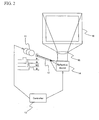
- Fig. 2 is a block diagram illustrating the configuration of a field-sequential DLP system equipped with a LED light source.
- the light emitted from a light source 1 including LEDs having colors of R, G, and B are led, through a light pipe 12, to a reflective device 14, such as a DMD, which is controlled by a controller 13 in synchronization with the light emission of each of the RGB colors of the LEDs 1.
- the light is then reflected by the reflective device 14.
- the resultant light then passes through a projector lens 15, and then is projected onto a projection screen 16. Thereby, an image is produced.
- the DLP system equipped with the LED light source and shown in Fig. 2 can have the same effect as in the case of using ND in the DLP system equipped with the color wheel and shown in Fig. 1 .
- This is achieved by a reduction in the amount of light emitted by the LEDs, which is achieved by a reduction in the current flowing through the LEDs.
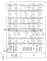
- Fig. 3 shows a comparison between the timings at which light of each color is emitted in the DLP system equipped with the color wheel and the corresponding timings in the DLP system equipped with the LED light source.
- the light of ND is produced by employing a deep-green ND segment in the DLP system with the color wheel whereas the DLP system with the LED light source reduces the amount of light emitted from the G (green) LED to produce the ND light.
- Fig. 4 is a diagram illustrating a circuit of a conventional LED driving device.
- the LED driving device can switch the current flowing through each of the LEDs between two different levels, and can thereby change the amount of light emitted from each LED between two different levels. This function is used for switching between the normal light emission of the green LED, which is the emission of normal green light, and the ND light emission, that is, when the green LED is used to function as the ND.
- Reference numerals R1001 to R1015 denote resistors, and reference numerals Q1001 to Q1010 denote transistors.
- LED_VCC shown in the upper right-hand portion of Fig. 4 denotes a power source to drive the LEDs with a large electric power.
- LED_GND denotes a ground for the power source.
- Connectors connected to a microcomputer and to a DAC are shown in the lower right-hand portion of Fig. 4 .
- VCC+3.3V denotes a 3.3-V power source for a control circuit.
- LED ON denotes a timing pulse which is supplied by the DAC and which makes the LEDs emit normal light. When this signal is high, the LEDs emit normal light.
- ND1 denotes a timing pulse which is supplied by the DAC and which makes the LEDs emit ND light. When this signal is high, the LEDs emit ND light.
- GND denotes a reference ground of the circuit.
- DAC IN denotes a potential which takes a fixed value set (adjusted) basically within the 256 different levels ranging from the GND level to the VCC level. Changing this value of potential allows the current flowing through the LEDs to be changed.
- Fig. 4 The portion enclosed by the dotted lines in Fig. 4 is a regulator unit.
- the LED driving device shown in Fig. 4 employs a series-regulator configuration. Nonetheless, even with a switching-regulator configuration, the concept with respect to the feedback is still the same.
- the driving voltage for the LEDs denoted by the LED ON passes through an and-circuit including transistors Q1009 and Q1010 into which the LED-ON and the ND supplied by the DAC, and then is switched by the transistor Q1008.
- the transistor Q1003 is provided for the regulation of the driving voltage thus switched.
- the transistors Q1002 and Q1004 constitute a differential circuit.
- the transistors Q1001 and Q1005 constitute an interface circuit for inputting a signal to the differential circuit.
- the current having flowed through the LEDs flows through a resistor network including the resistors R1001 and R1002.
- a voltage is generated between the GND of the resistor network and the cathodes of the LEDs. The voltage thus generated passes through the transistor Q1001 and returns to the transistor Q1002.
- the differential circuit including the transistors Q1002 and Q1004 controls the base current of the transistor Q1003 so that the voltage applied to the base of the transistor Q1004 can be the same as the base voltage of the transistor Q1002. Accordingly, the potential applied to the resistor network including the resistors R1001 and R1002 is fixed to a certain value, so that the fixed value of the current flowing through the resistor network can be determined uniquely. As a consequence, the current flowing through the LEDs is made constant.
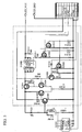
- Fig. 5 is a diagram illustrating a circuit of the LED driving device of the present invention.
- Reference numerals R1001 to R1015, and R2001 denote resistors.
- Reference numerals Q1001 to Q1010, and Q2001 denote transistors.
- LED_VCC shown in the upper right-hand portion of Fig. 5 denotes a power source to drive the LEDs with a large electric power.
- LED_GND denotes a ground for the power source.
- Connectors connected to a microcomputer and to a DAC are shown in the lower right-hand portion of Fig. 5 .
- VCC+3.3V denotes a 3.3-V power source for a control circuit.
- LED ON denotes a timing pulse which is supplied by the DAC and which makes the LEDs emit normal light.
- ND1 denotes a timing pulse which is supplied by the DAC and which makes the LEDs emit ND light.
- GND denotes a reference ground of the circuit.
- DAC IN denotes a potential which takes a fixed value set (adjusted) basically within the 256 different levels ranging from the GND level to the VCC level. Changing this value of potential allows the current flowing through the LEDs to be changed.
- Fig. 5 The portion enclosed by the dotted lines in Fig. 5 is a regulator unit.
- the LED driving device shown in Fig. 5 also employs a series-regulator configuration. Nonetheless, even with a switching-regulator configuration, the concept with respect to the feedback is still the same.
- the driving voltage for the LEDs denoted by the LED ON passes through an and-circuit including transistors Q1009 and Q1010 into which the LED-ON and the ND supplied by the DAC, and then is switched by the transistor Q1008.
- the transistor Q1003 is provided for the regulation of the driving voltage thus switched.
- the transistors Q1002 and Q1004 constitute a differential circuit.
- the transistors Q1001 and Q1005 constitute an interface circuit for inputting a signal into the differential circuit.
- the current having flowed through the LEDs flows through a resistor network including the resistors R1001, R1002, and R2001.
- a voltage is generated between the GND of the resistor network and the cathodes of the LEDs. The voltage thus generated passes through the transistor Q1001 and returns to the transistor Q1002.
- the differential circuit including the transistors Q1002 and Q1004 controls the base current of the transistor Q1003 so that the voltage applied to the base of the transistor Q1004 can be the same as the base voltage of the transistor Q1002. Accordingly, the potential applied to the resistor network is fixed to a certain value, so that the fixed value of the current flowing through the resistor network can be determined uniquely. As a consequence, the current flowing through the LEDs is made constant.
- the value of the current flowing through the feedback route is switched by the transistor Q2001 in accordance with the driving current of the LEDs so that the driving current is reduced except for the case of the emission of the normal light.
- the controlling of a minute current is not possible with the conventional feedback configuration as shown in Fig. 4 .
- the gate of the transistor Q2001 is controlled by the LED ON.
- the LEDs emit the ND light, that is, when the LED ON is high, the transistor Q2001 is in operation and, in the circuit, the resistor R2001 is made to be equivalent to the ground. Accordingly, in this case, the current flowing through the LEDs is determined by the value of the combined resistor including the two resistors R1001 and R1002.
- the transistor Q2001 When the LEDs emit the ND light, that is, when the LED ON is low, the transistor Q2001 is not in operation, so that the circuit as a whole becomes equivalent to a circuit without the Q2001. Accordingly, in this case, the current flowing through the LEDs is determined by the value of the combined resistor including the three resistors R1001, R1002, and R2001.
- the current is controlled by switching the voltage supplied from the DAC, and the value of the current is switched by the feedback route. Accordingly, a minute current can be controlled.
- the use of the LED driving device of the present invention in a display device can result in the effect obtainable by use of the ND filter in a conventional system equipped with a color wheel. As a consequence, a video image can be formed with a reduced quantization noise.
- the present invention is not limited to the above-described embodiment, but is applicable to other uses.
- the present invention can be carried out as an illuminating device equipped with a light source of LED and a device enabling the adjustment of the amount of light.
- the LED driving device of the present invention is applicable to an area-active circuit of a backlighting system (driven by LEDs) for a liquid-crystal display.
- the backlighting system for a liquid-crystal display of today employs either CCFLs (Cold-Cathode fluorescent lamps) or LEDs as its light source.
- CCFLs Cold-Cathode fluorescent lamps
- LEDs As to the LEDs, some of the backlighting systems for liquid-crystal displays, which now has a wider gamut of colors, employ LEDs of RGB colors. Occurrence of shallow black expression is one of the drawbacks of liquid-crystal displays, and it is pointed out that liquid-crystal displays have a weakness in the expressions of the black gradation.
- a method known as the area-active control is one of the means for addressing the above-mentioned problem.
- the area-active control the backlighting system is divided into several blocks, and the amount of light emitted from the light source for each of the blocks thus divided is controlled in synchronization with the video signals.
- An area-active circuit employed in the LED driving device of the present invention is capable of linearly changing the amount of emitted light, so that a wider dynamic range of the amount of emitted light can be obtained.
- Fig. 6 is a diagram illustrating a state of a backlighting system of a liquid-crystal television equipped with the LED driving device of the present invention.
- the LEDs provided in the backlighting system are grouped into blocks, and the brightness of the LEDs in each block is changed in accordance with the information on the intensity of the video image to be displayed. In this way, the problem of the shallow black expression, which is one of the drawbacks of liquid-crystal television, is improved.
- Fig. 7 illustrates typical characteristics of the conventional LED driving device shown in Fig. 4 .
- the horizontal axis represents the voltage to control the current, and the vertical axis represents the current flowing through the LEDs.
- Fig. 8 illustrates typical characteristics of the LED driving device of the present invention shown in Fig. 5 .
- the horizontal axis represents the voltage to control the current
- the vertical axis represents the current flowing through the LEDs.
- the LED driving circuit of the present invention has characteristics associated with two different modes. The controlling of a wide-range current flowing through the LEDs is accomplished by switching these modes (with the ND terminal in Fig. 5 ).
- the LED driving device of the present invention enables a significantly wider dynamic range.
- the backlighting system of a liquid crystal television equipped with the LED driving device of the present invention can have an effect of improving the above-mentioned shallow black expression.
- the LED driving device shown in Fig. 4 When the conventional LED driving device shown in Fig. 4 is used in the backlighting system of a direct-view type display device, the LED driving device is formed as a circuit without the transistor Q1010. This LED driving device is designed with such specifications that the amount of light emitted from the LEDs can be changed between two different levels by changing the current flowing through the LEDs between two different levels. Accordingly, the LED driving device can be used by switching the control range of the DAC between two different levels.
- Reference numerals R1001 to R1015 denote resistors, and reference numerals Q1001 to Q1010 denote transistors.
- LED_VCC shown in the upper right-hand portion of Fig. 4 denotes a power source to drive the LEDs with a large electric power.
- LED_GND denotes a ground for the power source.
- Connectors connected to a microcomputer and to a DAC are shown in the lower right-hand portion of Fig. 4 .
- VCC+3.3V denotes a 3.3-V power source for a control circuit.
- LED ON denotes a signal that is high when the backlight is lit.
- GND denotes a reference ground of the circuit.
- DAC IN denotes a variable value ranging basically from the GND level to the VCC level. This signal allows the current flowing through the LEDs to be changed.
- Fig. 4 The portion enclosed by the dotted lines in Fig. 4 is a regulator unit.
- the LED driving device shown in Fig. 4 employs a series-regulator configuration. Nonetheless, with a switching-regulator configuration, the concept with respect to the feedback is still the same.
- the driving voltage for the LEDs denoted by the LED ON switches the transistor Q1008 by means of the transistor Q1009 (the transistor Q1010 is not mounted on the circuit).
- the transistor Q1003 is provided for the regulation of the driving voltage thus switched.
- the transistors Q1002 and Q1004 constitute a differential circuit.
- the transistors Q1001 and Q1005 constitute an interface circuit for inputting a signal into the differential circuit.
- the current having flowed through the LEDs flows through a resistor network including the resistors R1001 and R1002.
- a voltage is generated between the GND of the resistor network and the cathodes of the LEDs. The voltage thus generated passes through the transistor Q1001 and returns to the transistor Q1002.
- the differential circuit including the transistors Q1002 and Q1004 controls the base current of the transistor Q1003 so that the voltage applied to the base of the transistor Q1004 can be the same as the base voltage of the transistor Q1002. Accordingly, the potential applied to the resistor network including the resistors R1001 and R1002 changes in accordance with the change in the DACIN, and the current flowing through the LEDs changes in response directly to the video image.
- Fig. 10 is a circuit diagram illustrating a circuit of the LED driving device of the present invention.
- Reference numerals R1001 to R1015, and R2001 denote resistors.
- Reference numerals Q1001 to Q1010, and Q2001 denote transistors.
- LED_VCC shown in the upper right-hand portion of Fig. 10 denotes a power source to drive the LEDs with a large electric power.
- LED_GND denotes a ground for the power source.
- Connectors connected to a microcomputer and to a DAC are shown in the lower right-hand portion of Fig. 10 .
- VCC+3.3V denotes a 3.3-V power source for a control circuit.
- LED ON denotes a signal that is high when the backlight is lit.
- GND denotes a reference ground of the circuit.
- DAC IN denotes a variable value ranging basically from the GND level to the VCC level. This signal allows the current flowing through the LED to be changed.
- Fig. 10 The portion enclosed by the dotted lines in Fig. 10 is a regulator unit.
- the LED driving device shown in Fig. 10 also employs a series-regulator configuration. Nonetheless, with a switching-regulator configuration, the concept with respect to the feedback is still the same.
- the driving voltage for the LEDs denoted by the LED ON switches the transistor Q1008 by means of the transistor Q1009 (the transistor Q1010 is not mounted on the circuit).
- the transistor Q1003 is provided for the regulation of the driving voltage thus switched.
- the transistors Q1002 and Q1004 constitute a differential circuit.
- the transistors Q1001 and Q1005 constitute an interface circuit for inputting a signal into the differential circuit.
- the current having flowed through the LEDs flows through a resistor network including the resistors R1001, R1002, and R2001.
- a voltage is generated between the GND of the resistor network and the cathodes of the LEDs. The voltage thus generated passes through the transistor Q1001 and returns to the transistor Q1002.
- the differential circuit including the transistors Q1002 and Q1004 controls the base current of the transistor Q1003 so that the voltage applied to the base of the transistor Q1004 can be the same as the base voltage of the transistor Q1002. Accordingly, the potential applied to the resistor network including the resistors R1001 and R1002 changes in accordance with the change in the DACIN, and the current flowing through the LEDs changes in response directly to the video image.
- the value of the current flowing through the feedback route is switched by the transistor Q2001 in accordance with the driving current of the LEDs so that the driving current is reduced except for the case of the emission of the normal light.
- the controlling of a minute current is not possible with the conventional feedback configuration as shown in Fig. 4 .
- the gate of the transistor Q2001 is controlled by the inversion signal of the ND.
- the transistor Q2001 is in operation and, in the circuit, the resistor R2001 is made to be equivalent to the ground. Accordingly, in this case, the current flowing through the LEDs is determined by the value of the combined resistor including the two resistors R1001 and R1002.
- the LEDs emit the ND light, that is, when the gate voltage of the transistor Q2001 is low, the transistor Q2001 is not in operation, so that the circuit as a whole becomes equivalent to a circuit without the Q2001. Accordingly, in this case, the current flowing through the LEDs is determined by the value of the combined resistor including the three resistors R1001, R1002, and R2001.
- the current is controlled by the video image applied to the DACIN, and the value of the current is switched by the feedback route. Accordingly, a minute current can be controlled.
- the use of the LED driving device of the present invention in a direct-view type display device can result in the effect obtainable by the conventional light modulation method with the pulse light emission. As a consequence, a reduction in the switching noise is possible.
- a second case has been described using an example of a liquid-crystal display system equipped with a backlighting system including a LED light source.
- the present invention is not limited to the above-described embodiment, but is applicable to other uses.
- the present invention can be carried out as an illuminating device equipped with a light source of LED and as a device enabling the adjustment of the amount of light.
- the LED driving device of the present invention can also be used as a driving device for LEDs used in a display device.
- LEDs have been used in the displays of electric signboard and the like for expressing simple characters and the like.
- Some of these electric signboards used in pachinko parlors and the like express animation and the like, but the quality of the video image has not reached a level equivalent to liquid-crystal displays.
- the driving current for LEDs to be driven can be changed dynamically. Accordingly, the use of the LED driving device of the present invention allows not only the expression of colors achieved conventionally by the simple combination of the ON/OFF of the RGB colors but also the expression of a wider variety of colors.
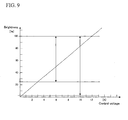
- each of the LED driving devices of the present invention shown in Figs. 5 and 10 has the characteristics associated with two different modes.
- the LED driving devices of the present invention switches these two modes, and thereby controls a wider-range current flowing through the LEDs. Accordingly, the relationship between the brightness of the LEDs and the current flowing through the LEDs is determined as shown in Fig. 9 , so that a significantly wider dynamic range can be achieved by use of the LED driving device of the present invention.
- What is made possible accordingly is a control appropriate for the light-intensity variation that is necessary for the signal of a video image divided into the RGB colors. Thereby, a wider variety of colors can be expressed by individually changing the brightness of the RGB colors.
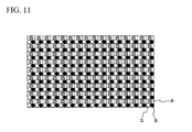
- Fig. 11 is a diagram illustrating the concept of an LED display device employing the LED driving device of the present invention.
- the LED display device includes multiple packages of LEDs while a single package includes a red LED, a green LED, and a blue LED, and the LEDs are driven individually by the LED driving device of the present invention. What is achieved accordingly is an expression of fine light-intensity differences.
- the present invention is applicable to an LED driving device.
Landscapes
- Engineering & Computer Science (AREA)
- Physics & Mathematics (AREA)
- Computer Hardware Design (AREA)
- General Physics & Mathematics (AREA)
- Theoretical Computer Science (AREA)
- Circuit Arrangement For Electric Light Sources In General (AREA)
- Control Of Indicators Other Than Cathode Ray Tubes (AREA)
- Led Devices (AREA)
- Liquid Crystal (AREA)
Applications Claiming Priority (2)
| Application Number | Priority Date | Filing Date | Title |
|---|---|---|---|
| JP2006285323 | 2006-10-19 | ||
| PCT/JP2007/070338 WO2008047862A1 (fr) | 2006-10-19 | 2007-10-18 | Dispositif de commande de diodes électroluminescentes, dispositif d'éclairage et dispositif d'affichage |
Publications (2)
| Publication Number | Publication Date |
|---|---|
| EP2096903A1 true EP2096903A1 (fr) | 2009-09-02 |
| EP2096903A4 EP2096903A4 (fr) | 2011-04-20 |
Family
ID=39314080
Family Applications (1)
| Application Number | Title | Priority Date | Filing Date |
|---|---|---|---|
| EP07830072A Withdrawn EP2096903A4 (fr) | 2006-10-19 | 2007-10-18 | Dispositif de commande de diodes électroluminescentes, dispositif d'éclairage et dispositif d'affichage |
Country Status (5)
| Country | Link |
|---|---|
| US (1) | US8310173B2 (fr) |
| EP (1) | EP2096903A4 (fr) |
| JP (1) | JP5016607B2 (fr) |
| CN (1) | CN101543137B (fr) |
| WO (1) | WO2008047862A1 (fr) |
Families Citing this family (7)
| Publication number | Priority date | Publication date | Assignee | Title |
|---|---|---|---|---|
| US8648358B2 (en) | 2009-02-19 | 2014-02-11 | Sharp Kabushiki Kaisha | Light emitting device, planar light source, and display device |
| JP2012099728A (ja) | 2010-11-04 | 2012-05-24 | Nikon Corp | 発光素子パッケージ及び表示装置 |
| CN102214451B (zh) * | 2011-06-10 | 2012-11-28 | 华东师范大学 | 一种基于光波长带通滤波器的数字光处理显示系统 |
| WO2014087876A1 (fr) * | 2012-12-04 | 2014-06-12 | シャープ株式会社 | Dispositif d'affichage d'image et son procédé de pilotage |
| KR101902391B1 (ko) * | 2016-12-22 | 2018-10-01 | 오스템임플란트 주식회사 | 구강 내부의 영상 데이터 처리 방법 및 구강 스캐너 |
| CN109254487B (zh) * | 2018-09-17 | 2021-02-19 | 苏州佳世达光电有限公司 | 投影装置 |
| CN111341230B (zh) * | 2018-12-19 | 2024-06-25 | 青岛海信激光显示股份有限公司 | 投影显示装置及其控制方法 |
Family Cites Families (18)
| Publication number | Priority date | Publication date | Assignee | Title |
|---|---|---|---|---|
| US5748164A (en) | 1994-12-22 | 1998-05-05 | Displaytech, Inc. | Active matrix liquid crystal image generator |
| US5767828A (en) | 1995-07-20 | 1998-06-16 | The Regents Of The University Of Colorado | Method and apparatus for displaying grey-scale or color images from binary images |
| US5812303A (en) * | 1996-08-15 | 1998-09-22 | Texas Instruments Incorporated | Light amplitude modulation with neutral density filters |
| JP4474562B2 (ja) | 2000-04-28 | 2010-06-09 | 東芝ライテック株式会社 | 発光ダイオード駆動装置 |
| JP2002203988A (ja) | 2000-12-28 | 2002-07-19 | Toshiba Lsi System Support Kk | 発光素子駆動回路 |
| JP3653078B2 (ja) * | 2002-12-12 | 2005-05-25 | 東光株式会社 | スイッチング定電流電源装置 |
| US7122973B1 (en) * | 2002-12-23 | 2006-10-17 | Kevin Thomas Ivers | Light-generating apparatus control system |
| JP2004274872A (ja) | 2003-03-07 | 2004-09-30 | Toko Inc | スイッチング定電流電源装置 |
| JP4030903B2 (ja) * | 2003-03-14 | 2008-01-09 | 株式会社小糸製作所 | 車両用灯具 |
| JP4187565B2 (ja) * | 2003-03-28 | 2008-11-26 | 株式会社モリテックス | 照明装置 |
| JP2004311635A (ja) * | 2003-04-04 | 2004-11-04 | Olympus Corp | 駆動装置及びそれを用いた照明装置、並びに、その照明装置を用いた表示装置 |
| JP2005005112A (ja) * | 2003-06-11 | 2005-01-06 | Yazaki Corp | Led駆動回路 |
| JP4370901B2 (ja) | 2003-10-15 | 2009-11-25 | パナソニック電工株式会社 | Led点灯装置 |
| US6995519B2 (en) * | 2003-11-25 | 2006-02-07 | Eastman Kodak Company | OLED display with aging compensation |
| KR100659531B1 (ko) * | 2003-11-27 | 2006-12-19 | 삼성에스디아이 주식회사 | 백라이트 구동회로 |
| US7527388B2 (en) * | 2003-12-09 | 2009-05-05 | Surefire Llc | Flashlight with detented rotary control |
| JP2005235826A (ja) * | 2004-02-17 | 2005-09-02 | Pioneer Electronic Corp | 点灯装置および照明装置 |
| US7108413B2 (en) * | 2004-03-11 | 2006-09-19 | Avago Technologies Ecbu Ip (Singapore) Pte. Ltd. | Sampling for color control feedback using an optical cable |
-
2007
- 2007-10-18 US US12/446,040 patent/US8310173B2/en not_active Expired - Fee Related
- 2007-10-18 WO PCT/JP2007/070338 patent/WO2008047862A1/fr not_active Ceased
- 2007-10-18 JP JP2008539862A patent/JP5016607B2/ja not_active Expired - Fee Related
- 2007-10-18 CN CN2007800435622A patent/CN101543137B/zh not_active Expired - Fee Related
- 2007-10-18 EP EP07830072A patent/EP2096903A4/fr not_active Withdrawn
Also Published As
| Publication number | Publication date |
|---|---|
| CN101543137A (zh) | 2009-09-23 |
| US20100295466A1 (en) | 2010-11-25 |
| JPWO2008047862A1 (ja) | 2010-02-25 |
| WO2008047862A1 (fr) | 2008-04-24 |
| US8310173B2 (en) | 2012-11-13 |
| JP5016607B2 (ja) | 2012-09-05 |
| CN101543137B (zh) | 2012-11-28 |
| EP2096903A4 (fr) | 2011-04-20 |
Similar Documents
| Publication | Publication Date | Title |
|---|---|---|
| CN101185021B (zh) | 发光二极管(led)照明控制系统和方法 | |
| CN101379545B (zh) | 液晶显示装置 | |
| US8310173B2 (en) | LED driving device, illuminating device, and display device | |
| US20100097412A1 (en) | Light source device and liquid crystal display unit | |
| US20100321417A1 (en) | Display device and projection display device | |
| US8184136B2 (en) | Image display device provided with multiple light sources emitting different colors to display color images in color sequential display method | |
| US20100013866A1 (en) | Light source device and liquid crystal display unit | |
| CN102939627B (zh) | 显示信号发生器、显示装置以及图像显示方法 | |
| CN1643937A (zh) | 具有根据图象信号进行调制的光源的图象投影仪 | |
| US20070262733A1 (en) | Control method and control driving device for backlight module | |
| CN101499240B (zh) | 图像显示装置以及电子设备 | |
| JP4068551B2 (ja) | 光源装置およびその駆動方法ならび映像表示装置 | |
| US20100149084A1 (en) | Backlight Device and Image Display Device Provided Therewith | |
| JP2007171258A (ja) | 映像表示装置 | |
| US20090109248A1 (en) | Display Apparatus Having a Multiplicity of Pixels and Method for Displaying Images | |
| JP2005070690A (ja) | 液晶表示装置 | |
| US8760383B2 (en) | Backlight module for displays | |
| US6650311B1 (en) | Control of video signal inversion frequency independently of frame or field frequency | |
| KR20050085772A (ko) | Lcd 디스플레이 패널용 스크롤링 백라이트 디바이스 | |
| CN101568955B (zh) | 确定一个显示图像的lcd面板的背光颜色和亮度的方法 | |
| CN101568956A (zh) | 增强lcd设备上显示图像的方法和装置 | |
| JP4023125B2 (ja) | 照明装置ならびに投射型表示装置とその駆動方法 | |
| JP2005534987A (ja) | 交流動作ランプを用いたスクローリング・カラー・システム | |
| JP4609385B2 (ja) | 表示装置および投射型表示装置 | |
| JP2016033672A (ja) | プロジェクターおよびプロジェクターの制御方法 |
Legal Events
| Date | Code | Title | Description |
|---|---|---|---|
| PUAI | Public reference made under article 153(3) epc to a published international application that has entered the european phase |
Free format text: ORIGINAL CODE: 0009012 |
|
| 17P | Request for examination filed |
Effective date: 20090519 |
|
| AK | Designated contracting states |
Kind code of ref document: A1 Designated state(s): AT BE BG CH CY CZ DE DK EE ES FI FR GB GR HU IE IS IT LI LT LU LV MC MT NL PL PT RO SE SI SK TR |
|
| DAX | Request for extension of the european patent (deleted) | ||
| RIC1 | Information provided on ipc code assigned before grant |
Ipc: G09G 3/34 20060101AFI20110310BHEP Ipc: G09G 3/20 20060101ALI20110310BHEP Ipc: G02F 1/13357 20060101ALI20110310BHEP Ipc: G09G 3/32 20060101ALI20110310BHEP Ipc: H05B 33/08 20060101ALI20110310BHEP Ipc: H01L 33/00 20100101ALI20110310BHEP Ipc: H05B 37/02 20060101ALI20110310BHEP |
|
| A4 | Supplementary search report drawn up and despatched |
Effective date: 20110322 |
|
| 17Q | First examination report despatched |
Effective date: 20121112 |
|
| STAA | Information on the status of an ep patent application or granted ep patent |
Free format text: STATUS: EXAMINATION IS IN PROGRESS |
|
| GRAP | Despatch of communication of intention to grant a patent |
Free format text: ORIGINAL CODE: EPIDOSNIGR1 |
|
| STAA | Information on the status of an ep patent application or granted ep patent |
Free format text: STATUS: GRANT OF PATENT IS INTENDED |
|
| INTG | Intention to grant announced |
Effective date: 20190628 |
|
| STAA | Information on the status of an ep patent application or granted ep patent |
Free format text: STATUS: THE APPLICATION IS DEEMED TO BE WITHDRAWN |
|
| 18D | Application deemed to be withdrawn |
Effective date: 20191109 |