EP2097048B1 - Orthopädietechnisches gerät - Google Patents
Orthopädietechnisches gerät Download PDFInfo
- Publication number
- EP2097048B1 EP2097048B1 EP07872086A EP07872086A EP2097048B1 EP 2097048 B1 EP2097048 B1 EP 2097048B1 EP 07872086 A EP07872086 A EP 07872086A EP 07872086 A EP07872086 A EP 07872086A EP 2097048 B1 EP2097048 B1 EP 2097048B1
- Authority
- EP
- European Patent Office
- Prior art keywords
- generator
- orthopedic device
- energy
- transmission
- components
- Prior art date
- Legal status (The legal status is an assumption and is not a legal conclusion. Google has not performed a legal analysis and makes no representation as to the accuracy of the status listed.)
- Not-in-force
Links
Images



Classifications
-
- A—HUMAN NECESSITIES
- A61—MEDICAL OR VETERINARY SCIENCE; HYGIENE
- A61F—FILTERS IMPLANTABLE INTO BLOOD VESSELS; PROSTHESES; DEVICES PROVIDING PATENCY TO, OR PREVENTING COLLAPSING OF, TUBULAR STRUCTURES OF THE BODY, e.g. STENTS; ORTHOPAEDIC, NURSING OR CONTRACEPTIVE DEVICES; FOMENTATION; TREATMENT OR PROTECTION OF EYES OR EARS; BANDAGES, DRESSINGS OR ABSORBENT PADS; FIRST-AID KITS
- A61F5/00—Orthopaedic methods or devices for non-surgical treatment of bones or joints; Nursing devices ; Anti-rape devices
- A61F5/01—Orthopaedic devices, e.g. long-term immobilising or pressure directing devices for treating broken or deformed bones such as splints, casts or braces
- A61F5/0102—Orthopaedic devices, e.g. long-term immobilising or pressure directing devices for treating broken or deformed bones such as splints, casts or braces specially adapted for correcting deformities of the limbs or for supporting them; Ortheses, e.g. with articulations
-
- A—HUMAN NECESSITIES
- A61—MEDICAL OR VETERINARY SCIENCE; HYGIENE
- A61F—FILTERS IMPLANTABLE INTO BLOOD VESSELS; PROSTHESES; DEVICES PROVIDING PATENCY TO, OR PREVENTING COLLAPSING OF, TUBULAR STRUCTURES OF THE BODY, e.g. STENTS; ORTHOPAEDIC, NURSING OR CONTRACEPTIVE DEVICES; FOMENTATION; TREATMENT OR PROTECTION OF EYES OR EARS; BANDAGES, DRESSINGS OR ABSORBENT PADS; FIRST-AID KITS
- A61F2/00—Filters implantable into blood vessels; Prostheses, i.e. artificial substitutes or replacements for parts of the body; Appliances for connecting them with the body; Devices providing patency to, or preventing collapsing of, tubular structures of the body, e.g. stents
- A61F2/50—Prostheses not implantable in the body
- A61F2/68—Operating or control means
- A61F2/70—Operating or control means electrical
-
- A—HUMAN NECESSITIES
- A61—MEDICAL OR VETERINARY SCIENCE; HYGIENE
- A61F—FILTERS IMPLANTABLE INTO BLOOD VESSELS; PROSTHESES; DEVICES PROVIDING PATENCY TO, OR PREVENTING COLLAPSING OF, TUBULAR STRUCTURES OF THE BODY, e.g. STENTS; ORTHOPAEDIC, NURSING OR CONTRACEPTIVE DEVICES; FOMENTATION; TREATMENT OR PROTECTION OF EYES OR EARS; BANDAGES, DRESSINGS OR ABSORBENT PADS; FIRST-AID KITS
- A61F2/00—Filters implantable into blood vessels; Prostheses, i.e. artificial substitutes or replacements for parts of the body; Appliances for connecting them with the body; Devices providing patency to, or preventing collapsing of, tubular structures of the body, e.g. stents
- A61F2/50—Prostheses not implantable in the body
- A61F2/60—Artificial legs or feet or parts thereof
- A61F2/64—Knee joints
- A61F2/642—Polycentric joints, without longitudinal rotation
- A61F2/644—Polycentric joints, without longitudinal rotation of the single-bar or multi-bar linkage type
-
- A—HUMAN NECESSITIES
- A61—MEDICAL OR VETERINARY SCIENCE; HYGIENE
- A61F—FILTERS IMPLANTABLE INTO BLOOD VESSELS; PROSTHESES; DEVICES PROVIDING PATENCY TO, OR PREVENTING COLLAPSING OF, TUBULAR STRUCTURES OF THE BODY, e.g. STENTS; ORTHOPAEDIC, NURSING OR CONTRACEPTIVE DEVICES; FOMENTATION; TREATMENT OR PROTECTION OF EYES OR EARS; BANDAGES, DRESSINGS OR ABSORBENT PADS; FIRST-AID KITS
- A61F2/00—Filters implantable into blood vessels; Prostheses, i.e. artificial substitutes or replacements for parts of the body; Appliances for connecting them with the body; Devices providing patency to, or preventing collapsing of, tubular structures of the body, e.g. stents
- A61F2/50—Prostheses not implantable in the body
- A61F2/60—Artificial legs or feet or parts thereof
- A61F2/66—Feet; Ankle joints
- A61F2/6607—Ankle joints
-
- A—HUMAN NECESSITIES
- A61—MEDICAL OR VETERINARY SCIENCE; HYGIENE
- A61F—FILTERS IMPLANTABLE INTO BLOOD VESSELS; PROSTHESES; DEVICES PROVIDING PATENCY TO, OR PREVENTING COLLAPSING OF, TUBULAR STRUCTURES OF THE BODY, e.g. STENTS; ORTHOPAEDIC, NURSING OR CONTRACEPTIVE DEVICES; FOMENTATION; TREATMENT OR PROTECTION OF EYES OR EARS; BANDAGES, DRESSINGS OR ABSORBENT PADS; FIRST-AID KITS
- A61F2/00—Filters implantable into blood vessels; Prostheses, i.e. artificial substitutes or replacements for parts of the body; Appliances for connecting them with the body; Devices providing patency to, or preventing collapsing of, tubular structures of the body, e.g. stents
- A61F2/50—Prostheses not implantable in the body
- A61F2/76—Means for assembling, fitting or testing prostheses, e.g. for measuring or balancing, e.g. alignment means
-
- A—HUMAN NECESSITIES
- A61—MEDICAL OR VETERINARY SCIENCE; HYGIENE
- A61F—FILTERS IMPLANTABLE INTO BLOOD VESSELS; PROSTHESES; DEVICES PROVIDING PATENCY TO, OR PREVENTING COLLAPSING OF, TUBULAR STRUCTURES OF THE BODY, e.g. STENTS; ORTHOPAEDIC, NURSING OR CONTRACEPTIVE DEVICES; FOMENTATION; TREATMENT OR PROTECTION OF EYES OR EARS; BANDAGES, DRESSINGS OR ABSORBENT PADS; FIRST-AID KITS
- A61F2/00—Filters implantable into blood vessels; Prostheses, i.e. artificial substitutes or replacements for parts of the body; Appliances for connecting them with the body; Devices providing patency to, or preventing collapsing of, tubular structures of the body, e.g. stents
- A61F2/02—Prostheses implantable into the body
- A61F2/30—Joints
- A61F2002/30001—Additional features of subject-matter classified in A61F2/28, A61F2/30 and subgroups thereof
- A61F2002/30316—The prosthesis having different structural features at different locations within the same prosthesis; Connections between prosthetic parts; Special structural features of bone or joint prostheses not otherwise provided for
- A61F2002/30329—Connections or couplings between prosthetic parts, e.g. between modular parts; Connecting elements
- A61F2002/30518—Connections or couplings between prosthetic parts, e.g. between modular parts; Connecting elements with possibility of relative movement between the prosthetic parts
- A61F2002/30523—Connections or couplings between prosthetic parts, e.g. between modular parts; Connecting elements with possibility of relative movement between the prosthetic parts by means of meshing gear teeth
-
- A—HUMAN NECESSITIES
- A61—MEDICAL OR VETERINARY SCIENCE; HYGIENE
- A61F—FILTERS IMPLANTABLE INTO BLOOD VESSELS; PROSTHESES; DEVICES PROVIDING PATENCY TO, OR PREVENTING COLLAPSING OF, TUBULAR STRUCTURES OF THE BODY, e.g. STENTS; ORTHOPAEDIC, NURSING OR CONTRACEPTIVE DEVICES; FOMENTATION; TREATMENT OR PROTECTION OF EYES OR EARS; BANDAGES, DRESSINGS OR ABSORBENT PADS; FIRST-AID KITS
- A61F2/00—Filters implantable into blood vessels; Prostheses, i.e. artificial substitutes or replacements for parts of the body; Appliances for connecting them with the body; Devices providing patency to, or preventing collapsing of, tubular structures of the body, e.g. stents
- A61F2/50—Prostheses not implantable in the body
- A61F2002/5038—Hinged joint, e.g. with transverse axle restricting the movement
- A61F2002/5039—Hinged joint, e.g. with transverse axle restricting the movement allowing only for single rotation
-
- A—HUMAN NECESSITIES
- A61—MEDICAL OR VETERINARY SCIENCE; HYGIENE
- A61F—FILTERS IMPLANTABLE INTO BLOOD VESSELS; PROSTHESES; DEVICES PROVIDING PATENCY TO, OR PREVENTING COLLAPSING OF, TUBULAR STRUCTURES OF THE BODY, e.g. STENTS; ORTHOPAEDIC, NURSING OR CONTRACEPTIVE DEVICES; FOMENTATION; TREATMENT OR PROTECTION OF EYES OR EARS; BANDAGES, DRESSINGS OR ABSORBENT PADS; FIRST-AID KITS
- A61F2/00—Filters implantable into blood vessels; Prostheses, i.e. artificial substitutes or replacements for parts of the body; Appliances for connecting them with the body; Devices providing patency to, or preventing collapsing of, tubular structures of the body, e.g. stents
- A61F2/50—Prostheses not implantable in the body
- A61F2002/5072—Prostheses not implantable in the body having spring elements
- A61F2002/5073—Helical springs, e.g. having at least one helical spring
-
- A—HUMAN NECESSITIES
- A61—MEDICAL OR VETERINARY SCIENCE; HYGIENE
- A61F—FILTERS IMPLANTABLE INTO BLOOD VESSELS; PROSTHESES; DEVICES PROVIDING PATENCY TO, OR PREVENTING COLLAPSING OF, TUBULAR STRUCTURES OF THE BODY, e.g. STENTS; ORTHOPAEDIC, NURSING OR CONTRACEPTIVE DEVICES; FOMENTATION; TREATMENT OR PROTECTION OF EYES OR EARS; BANDAGES, DRESSINGS OR ABSORBENT PADS; FIRST-AID KITS
- A61F2/00—Filters implantable into blood vessels; Prostheses, i.e. artificial substitutes or replacements for parts of the body; Appliances for connecting them with the body; Devices providing patency to, or preventing collapsing of, tubular structures of the body, e.g. stents
- A61F2/50—Prostheses not implantable in the body
- A61F2002/5072—Prostheses not implantable in the body having spring elements
- A61F2002/5078—2-D spiral springs
-
- A—HUMAN NECESSITIES
- A61—MEDICAL OR VETERINARY SCIENCE; HYGIENE
- A61F—FILTERS IMPLANTABLE INTO BLOOD VESSELS; PROSTHESES; DEVICES PROVIDING PATENCY TO, OR PREVENTING COLLAPSING OF, TUBULAR STRUCTURES OF THE BODY, e.g. STENTS; ORTHOPAEDIC, NURSING OR CONTRACEPTIVE DEVICES; FOMENTATION; TREATMENT OR PROTECTION OF EYES OR EARS; BANDAGES, DRESSINGS OR ABSORBENT PADS; FIRST-AID KITS
- A61F2/00—Filters implantable into blood vessels; Prostheses, i.e. artificial substitutes or replacements for parts of the body; Appliances for connecting them with the body; Devices providing patency to, or preventing collapsing of, tubular structures of the body, e.g. stents
- A61F2/50—Prostheses not implantable in the body
- A61F2/60—Artificial legs or feet or parts thereof
- A61F2/66—Feet; Ankle joints
- A61F2002/6614—Feet
- A61F2002/6657—Feet having a plate-like or strip-like spring element, e.g. an energy-storing cantilever spring keel
- A61F2002/6692—Feet having a plate-like or strip-like spring element, e.g. an energy-storing cantilever spring keel circular or loop-shaped
-
- A—HUMAN NECESSITIES
- A61—MEDICAL OR VETERINARY SCIENCE; HYGIENE
- A61F—FILTERS IMPLANTABLE INTO BLOOD VESSELS; PROSTHESES; DEVICES PROVIDING PATENCY TO, OR PREVENTING COLLAPSING OF, TUBULAR STRUCTURES OF THE BODY, e.g. STENTS; ORTHOPAEDIC, NURSING OR CONTRACEPTIVE DEVICES; FOMENTATION; TREATMENT OR PROTECTION OF EYES OR EARS; BANDAGES, DRESSINGS OR ABSORBENT PADS; FIRST-AID KITS
- A61F2/00—Filters implantable into blood vessels; Prostheses, i.e. artificial substitutes or replacements for parts of the body; Appliances for connecting them with the body; Devices providing patency to, or preventing collapsing of, tubular structures of the body, e.g. stents
- A61F2/50—Prostheses not implantable in the body
- A61F2/68—Operating or control means
- A61F2002/6818—Operating or control means for braking
-
- A—HUMAN NECESSITIES
- A61—MEDICAL OR VETERINARY SCIENCE; HYGIENE
- A61F—FILTERS IMPLANTABLE INTO BLOOD VESSELS; PROSTHESES; DEVICES PROVIDING PATENCY TO, OR PREVENTING COLLAPSING OF, TUBULAR STRUCTURES OF THE BODY, e.g. STENTS; ORTHOPAEDIC, NURSING OR CONTRACEPTIVE DEVICES; FOMENTATION; TREATMENT OR PROTECTION OF EYES OR EARS; BANDAGES, DRESSINGS OR ABSORBENT PADS; FIRST-AID KITS
- A61F2/00—Filters implantable into blood vessels; Prostheses, i.e. artificial substitutes or replacements for parts of the body; Appliances for connecting them with the body; Devices providing patency to, or preventing collapsing of, tubular structures of the body, e.g. stents
- A61F2/50—Prostheses not implantable in the body
- A61F2/68—Operating or control means
- A61F2/70—Operating or control means electrical
- A61F2002/701—Operating or control means electrical operated by electrically controlled means, e.g. solenoids or torque motors
-
- A—HUMAN NECESSITIES
- A61—MEDICAL OR VETERINARY SCIENCE; HYGIENE
- A61F—FILTERS IMPLANTABLE INTO BLOOD VESSELS; PROSTHESES; DEVICES PROVIDING PATENCY TO, OR PREVENTING COLLAPSING OF, TUBULAR STRUCTURES OF THE BODY, e.g. STENTS; ORTHOPAEDIC, NURSING OR CONTRACEPTIVE DEVICES; FOMENTATION; TREATMENT OR PROTECTION OF EYES OR EARS; BANDAGES, DRESSINGS OR ABSORBENT PADS; FIRST-AID KITS
- A61F2220/00—Fixations or connections for prostheses classified in groups A61F2/00 - A61F2/26 or A61F2/82 or A61F9/00 or A61F11/00 or subgroups thereof
- A61F2220/0025—Connections or couplings between prosthetic parts, e.g. between modular parts; Connecting elements
Definitions
- the invention relates to an orthopedic device, in particular orthoses or prostheses, with each other pivotally mounted components.
- Orthopedic devices with two articulated and pivotally mounted components are equipped for certain applications with sensors and actuators.
- changes to the orthopedic device can be made, for example, the damping properties of a joint can be changed depending on the detected sensor data.
- sensors whose sensor signals are e.g. can be transmitted wirelessly to a receiver As a result, a monitoring or inspection of the device during use for the respective prosthesis user is possible, so that any necessary adjustments can be made easier.
- the sensors or actuators or transmitting devices are supplied with electrical energy of a rechargeable battery, which ensures undisturbed operation over a specified period. This period covers the usual activity period of a day, while the accumulator is charged during a passive period.
- the usable for the operation of orthopedic devices accumulators are limited in both their size and in their weight, since in orthopedic devices as small as possible and lightweight components to be installed. This results in a limited charge capacity of the accumulator. It is therefore problematic to provide additional sensors or actuators beyond a minimum configuration or an effective To provide support for a movement. Also, the operating times are limited.
- Object of the present invention is to improve an orthopedic device with two mutually pivotally mounted components and these optionally associated sensors or actuators so that a sufficient energy supply ensured and the lightest possible construction is achieved.
- the orthopedic device according to the invention with two mutually pivotally mounted components provides that a generator for generating electrical energy is arranged thereon.
- the generator is driven by a transmission device which transmits a relative movement of the two components to one another.
- a transmission device which converts a translatory or rotational movement such that a generator for generating electrical energy is preferably rotationally driven.
- This drive is preferably such that only one direction of rotation for the drive shafts of the generator is made possible to minimize the effort for a reversal of the direction of the generator.
- an energy store in particular a spring, can be loaded more easily, in particular tensioned and used effectively.
- the generator is preferably designed as an alternator, which is attached to the orthosis or prosthesis and supplies the energy-consuming components, such as actuators or sensors with energy.
- the generator works according to the dynamo principle of the electromagnetic induction and may alternatively be designed as a DC generator.
- a further homogenization of the energy supply by the generator is achieved in that the generator is preceded by an energy storage.
- the energy accumulator is preferably designed as a spring, in particular as a spiral or helical spring and serves for smoothing or for capturing motion impulses.
- Such springs are well known in the clock and ensure that the generator is optionally operated via the gearbox with a correspondingly high speed, as long as the bias of the spring is sufficiently high. Since both the transmission and the generator are kept in motion by the energy storage, no static friction effects or starting losses occur, which further increases the efficiency. To increase the efficiency and to even out the drive of the generator this is preferably preceded by a transmission that the relatively short movement length of two translated components to each other in a speed adapted to the generator.
- a development of the invention provides that the generator is associated with a locking device which blocks a drive of the generator when the energy storage device has a too low force level. This ensures that, for example, in the case of a spring energy store, the generator is put into operation only from a minimum voltage of the spring. This can be done by a mechanical lock of the generator, the energy storage device or an intermediate transmission or by an electrical blocking circuit that blocks, for example, a short circuit
- the transmission device has at least one freewheel, which blocks the power transmission in a fixed direction of rotation and only allows a power transmission in the other, released direction of rotation.
- a drive in a rotational direction is ensured in this way.
- the transmission device has a push rod which converts a rotation of two components, for example a foot part and a lower leg part or an upper part and a lower part of a knee joint device in a push movement.
- This thrust movement or translational movement takes place alternately, it being ensured by a corresponding control of the push rod that a drive of the generator or a loading of an energy storage device takes place only in one direction.
- the push rod By the push rod, a translation can be realized, so that the relatively small twist angle can be translated into large translational movements. It is also possible that the push rod over a Articulated gear is connected to the generator or the upstream transmission.
- the push rod may be assigned a ratchet mechanism which is effective only in one direction but slips in the other.
- the transmission device can transmit the rotational movement directly to the generator or an upstream power storage or an upstream transmission.
- the transmission of the pivoting of two components can be done by different means, such as toothed or friction wheels or traction drives such as chains, belts or timing belt.
- the various transmission means can be combined with one another in order to realize suitable translations, angles of rotation or displacement paths or to direct the forces and moments to the desired locations.
- the transmission device has a double gear arrangement with at least one switching device, which produces or enables a power transmission to an output shaft only in one direction of rotation, so that the gears are effective in a direction of force. It is envisaged that occurs in a gear reversing the direction of rotation, most easily by an intermediate gear to ensure a uniform direction of rotation of the output shaft and thus of the generator.
- a corresponding switching or, for example, slide guide it is possible that translational or rotary movements are transmitted in different directions to a respective gear that rotate by suitable translation devices, the drive shaft only in one direction and locked in the other direction or not driven.
- gears can also be provided with a freewheel and be driven at the same time, wherein a gear is provided with a device for reversing the direction of rotation, so that when alternating movements a drive takes place only in one direction.
- a particularly simple manner of force utilization and power transmission in only one direction of rotation exists when a bevel gear is provided, in which a drive bevel gear is coupled to two output bevel gears.
- the driven bevel gears are mounted on a common output shaft and each provided with a freewheel, which is designed so that the drive shaft is acted upon in one rotational direction with only one torque. Since both output gears are driven alternately in alternating rotational movements, only the one and in the rotation in the other direction of rotation, the opposite output gear is coupled to transmit power to the output shaft during rotation in one direction.
- the generator may be coupled to an accumulator or to a capacitor in order to provide not only a mechanical force storage but also an electrical force storage.
- a rectifier is provided to charge an accumulator.
- a constant output can be controlled via an additional mechanical brake. It is also possible to control the output via a short circuit in the generator. Due to the constant drive of the generator, a substantially constant power generation is possible, so that can be dispensed with a transformer, which has a positive effect on both the size and the weight.
- FIG. 1a shows in side view an orthopedic device 1 in the form of a leg prosthesis.
- a prosthetic knee joint 20 is disposed at the upper end and a prosthetic foot 30 is disposed at the lower end.
- a sole region 31 is fixed to a connecting element 33 via a spring 32.
- a hinge device 34 of the lower leg shaft 10 is pivotally mounted on a heel body 35, to which also the sole part 31 is attached.
- the prosthetic knee joint 20 is arranged with upper connecting means 21 for receiving a thigh shaft or the like.
- Lower connection means 23 fix the prosthetic knee joint 20 to the lower leg shaft 10.
- a multi-joint system 22 provides a hinged connection of the upper Connecting means 21 to the lower connection means 23 and the lower leg shaft 10th
- a generator unit 40 is fixed, which is driven by a transmission device 50.
- the transmission device 50 is arranged laterally next to the prosthetic knee joint 20 and has two wheels 52, 54 which are connected to one another via a toothed belt 53 or via another traction mechanism drive. This is more detailed in the Figure 1c to recognize.
- the prosthetic knee joint 20 has in the multi-joint system 22 on a front link 24 which is mounted relative to the lower attachment means 23 and thus to the lower leg 10 pivotally.
- the first drive wheel 52 is rotatably attached to the front link 24 or its axis of rotation, so that takes place in a flexion or extension of the prosthetic knee joint 20, a rotation of the front link 24.
- the alternating pivoting movements are indicated by the double arrow in the FIG. 1a indicated.
- the drive wheel 52 rotates correspondingly and correspondingly drives the toothed belt 53 or another force transmission element.
- a drive wheel 54 which is connected to the generator unit 40, is moved correspondingly alternatively about its axis of rotation. The rotation of the drive wheel 54 is transmitted to a generator, which will be explained later.
- the kinetic energy can be stored via a force storage device in the form of a spring. It is also possible to interpose a transmission unit.
- the rotational movement of the front link 24 is converted via the traction drive 53 in an immediate rotational movement of the drive wheel 54 and thus a drive shaft for the generator.
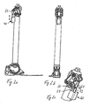
- FIGS. 2a to 2c represented according to the FIGS. 1a to 1c are constructed. Instead of a transmission of a pivoting of a front link 24, a relative gift of a rear link 25 about a lower axis of rotation 26 via two push rods 55, 56 transmitted to the generator unit 40. Instead of a lateral arrangement, as in the FIGS. 1a to 1c is shown, the knee joint 20 by the in the FIGS. 2a to 2c arrangement shown in sagittal plane behind each other narrower. At the engaging directly into the generator unit 40 push rod 55 has a toothing 58 is formed, via which a generator is driven directly or indirectly.
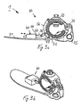
- a prosthetic foot 30 is shown as an orthopedic device 1, in which the energy conversion into electrical energy takes place directly on the prosthetic foot 30.
- the generator unit 40 is arranged on the sole part 31 and coupled via a rack 55 with a toothing 58 via a Mehrtenkergetriebe 56, 56 ', 57 with the pivotally mounted upper connecting part 33.
- the spring 32 is compressed or rolled so that the upper connection means 33 can pivot about the pivot axis 34 relative to the heel part 35 and the sole part 31.
- the rack 55 is moved forward via the multi-link transmission 56, 56 ', 57.
- FIGS. 4a and 4b An alternative embodiment of a prosthetic foot 30 is in the FIGS. 4a and 4b shown, in which the upper part 33 is pivotally mounted about a pivot axis 34 on a bearing bar 56, which in turn hinged to a vertical oriented rack is attached.
- the bearing bar 56 pivots about the pivot axis 34 'at a load and thus causes a movement of the rack 55 in the direction of the sole portion 31. If the load falls away, the illustrated starting position is taken by the spring 32 so that the rack 55 upwards is relocated. This is indicated by the double arrow.
- the support beam 56 is guided through a slot 36 within the spring 32, whereby a very compact structure can be realized.
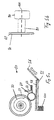
- FIG. 5 shows a schematic diagram of a transmission device 50 with a push rod 56, which performs an alternating, translational movement.
- the push rod 56 is coupled to a rack 55, on which a toothing 58 is arranged in the form of a sawtooth toothing.
- the rack 55 meshes with a gear 60, which in turn is in engagement with a further gear 61.
- a coil spring 70 is tensioned as an energy storage. If the rack 55 is shifted to the left, the gear 60 is rotated clockwise, whereby the second gear 61 is rotated counterclockwise and the coil spring 70 biases. When moving to the right, the teeth 58 slide over the gear 60 without causing any adjustment.
- a return spring 550 then presses the rack 55 against the gear 60 again to hold the teeth 58 in engagement.
- a mechanical brake 62 is biased by a spring 63 against the gear 60, so that a movement of the gear 60 is prevented in the counterclockwise direction.
- the gears 60, 61 may be coupled to one another in different ratios, optionally by an intermediate transmission.
- FIG. 5b is shown in side view, the assignment of the coil spring 70 via the gear 61 on a rotation axis 100.
- the torsion spring 70 drives a DC generator 90 via a gear 80 with a high reduction ratio. Once the transmission friction is overcome, the generator 90 comes through the strong reduction of the gear 80 in rotation and achieved corresponding bias of the spring 70 is a high speed, which is maintained as long as the tension of the spring 70 is sufficient.
- walking so achieved in the prosthetic foot 30 or in the prosthetic knee joint 20 and resulting short-term energy increases can be stored by the spring 70 in the form of repeated rotation of the spring 70 in a cocked position and slowly output via the gear 80 to the generator 90. This serves for smoothing and catching pulses and increasing the overall efficiency.
- a movement control for example by a sliding guide of the rack 55, can be dispensed with a ratchet design of the motion converter in the transmission device 50.
- alternating rotational movements can be converted via corresponding freewheel arrangements and a deflection such that a drive shaft for the generator 90 or for the pretensioning of the spring 70 is always rotated in only one direction.
- FIGS. 6a to 6c is an alternative or complementary implementation of an alternating translational movement in a rotary motion shown.
- a crank 64 Via a crank 64, a pivoting movement is transmitted in an alternating rotational movement to a shaft 65.
- a drive bevel gear 66 On this shaft 65, a drive bevel gear 66 is mounted, which corresponding to the rotational movement of the shaft 65 performs alternating rotational movements.
- the drive wheel 66 engage two mounted on a common output shaft 69 driven wheels 67, 68 in the form of bevel gears, which are each equipped with freewheel devices 670, 680. Rotates the shaft 65 and the drive gear 66 in the clockwise direction, as seen in the direction of FIG.
- the right driven gear 67 remains without power transmission while the left driven gear 68 drives the output shaft 69 accordingly.
- the shaft 65 rotates counterclockwise, whereby the left gear 68 via the freewheel 680 taken out of a force-transmitting engagement and instead the right Gear 67 is switched to transmit power.
- the output shaft 69 is rotated in only one direction of rotation.
- the output shaft 69 is coupled to a spiral or coil spring 70 as a mechanical energy storage, which in turn is coupled to a transmission unit 80.
- the generator 90 is driven via different transmission stages of the gear unit 80, whereby the kinetic energy is converted into electrical energy by the flexion and extension or the relative displacement of the components of the orthopedic device.
- This electrical energy can be transmitted directly to consumers, not shown, for example, actuators or sensors or transmitting devices. It is also possible for the generated electrical energy to be stored in accumulators or capacitors.
- the spring 70 can be controlled by a mechanical brake.
- a short circuit within the generator 90, the drive can also be controlled.
- the drive shaft 65 can also be driven in rotation directly via a toothed belt or the like.
- the drive shaft 65 or optionally also the generator shaft 100 is arranged directly on a rotational axis of the displaced component.
Landscapes
- Health & Medical Sciences (AREA)
- Animal Behavior & Ethology (AREA)
- Veterinary Medicine (AREA)
- Engineering & Computer Science (AREA)
- Biomedical Technology (AREA)
- Heart & Thoracic Surgery (AREA)
- Vascular Medicine (AREA)
- Life Sciences & Earth Sciences (AREA)
- Public Health (AREA)
- General Health & Medical Sciences (AREA)
- Orthopedic Medicine & Surgery (AREA)
- Nursing (AREA)
- Cardiology (AREA)
- Oral & Maxillofacial Surgery (AREA)
- Transplantation (AREA)
- Prostheses (AREA)
- Orthopedics, Nursing, And Contraception (AREA)
- Surgical Instruments (AREA)
- Massaging Devices (AREA)
Applications Claiming Priority (2)
| Application Number | Priority Date | Filing Date | Title |
|---|---|---|---|
| DE102006059206A DE102006059206B4 (de) | 2006-12-13 | 2006-12-13 | Orthopädietechnisches Gerät |
| PCT/IB2007/004480 WO2008072095A2 (de) | 2006-12-13 | 2007-12-12 | Orthopädietechnisches gerät |
Publications (2)
| Publication Number | Publication Date |
|---|---|
| EP2097048A2 EP2097048A2 (de) | 2009-09-09 |
| EP2097048B1 true EP2097048B1 (de) | 2010-09-01 |
Family
ID=39431319
Family Applications (1)
| Application Number | Title | Priority Date | Filing Date |
|---|---|---|---|
| EP07872086A Not-in-force EP2097048B1 (de) | 2006-12-13 | 2007-12-12 | Orthopädietechnisches gerät |
Country Status (10)
| Country | Link |
|---|---|
| US (1) | US8202325B2 (pt) |
| EP (1) | EP2097048B1 (pt) |
| CN (1) | CN101621973B (pt) |
| AT (1) | ATE479407T1 (pt) |
| BR (1) | BRPI0721090A2 (pt) |
| CA (1) | CA2676025C (pt) |
| DE (2) | DE102006059206B4 (pt) |
| RU (1) | RU2459596C2 (pt) |
| WO (1) | WO2008072095A2 (pt) |
| ZA (1) | ZA200904887B (pt) |
Families Citing this family (58)
| Publication number | Priority date | Publication date | Assignee | Title |
|---|---|---|---|---|
| US20040064195A1 (en) | 2002-07-15 | 2004-04-01 | Hugh Herr | Variable-mechanical-impedance artificial legs |
| US8075633B2 (en) | 2003-09-25 | 2011-12-13 | Massachusetts Institute Of Technology | Active ankle foot orthosis |
| US10307272B2 (en) | 2005-03-31 | 2019-06-04 | Massachusetts Institute Of Technology | Method for using a model-based controller for a robotic leg |
| US20060249315A1 (en) | 2005-03-31 | 2006-11-09 | Massachusetts Institute Of Technology | Artificial human limbs and joints employing actuators, springs, and variable-damper elements |
| US20070043449A1 (en) | 2005-03-31 | 2007-02-22 | Massachusetts Institute Of Technology | Artificial ankle-foot system with spring, variable-damping, and series-elastic actuator components |
| US10080672B2 (en) | 2005-03-31 | 2018-09-25 | Bionx Medical Technologies, Inc. | Hybrid terrain-adaptive lower-extremity systems |
| US8500823B2 (en) | 2005-03-31 | 2013-08-06 | Massachusetts Institute Of Technology | Powered artificial knee with agonist-antagonist actuation |
| US8864846B2 (en) | 2005-03-31 | 2014-10-21 | Massachusetts Institute Of Technology | Model-based neuromechanical controller for a robotic leg |
| US20070123997A1 (en) | 2005-03-31 | 2007-05-31 | Massachusetts Institute Of Technology | Exoskeletons for running and walking |
| US20070162152A1 (en) | 2005-03-31 | 2007-07-12 | Massachusetts Institute Of Technology | Artificial joints using agonist-antagonist actuators |
| US11278433B2 (en) | 2005-03-31 | 2022-03-22 | Massachusetts Institute Of Technology | Powered ankle-foot prosthesis |
| US8512415B2 (en) | 2005-03-31 | 2013-08-20 | Massachusetts Institute Of Technology | Powered ankle-foot prothesis |
| WO2008031220A1 (en) * | 2006-09-15 | 2008-03-20 | Bloorview Kids Rehab | A generator for prosthesis and orthosis |
| WO2008080231A1 (en) | 2007-01-05 | 2008-07-10 | Victhom Human Bionics Inc. | Joint actuation mechanism for a prosthetic and/or orthotic device having a compliant transmission |
| EP2120801B1 (en) | 2007-01-19 | 2018-04-11 | Victhom Laboratory Inc. | Reactive layer control system for prosthetic and orthotic devices |
| US11020248B2 (en) | 2007-09-19 | 2021-06-01 | Proteor USA, LLC | Vacuum system for a prosthetic foot |
| US10405998B2 (en) | 2007-09-19 | 2019-09-10 | Ability Dynamics Llc | Mounting bracket for connecting a prosthetic limb to a prosthetic foot |
| US12011373B2 (en) | 2007-09-19 | 2024-06-18 | Proteor USA, LLC | Mounting bracket for connecting a prosthetic limb to a prosthetic foot |
| US10842653B2 (en) | 2007-09-19 | 2020-11-24 | Ability Dynamics, Llc | Vacuum system for a prosthetic foot |
| CN102036626B (zh) | 2008-03-24 | 2014-07-02 | 奥瑟Hf公司 | 经股的假肢系统和用于操作该系统的方法 |
| US9180025B2 (en) * | 2008-04-21 | 2015-11-10 | Vanderbilt University | Powered leg prosthesis and control methodologies for obtaining near normal gait |
| US8652218B2 (en) | 2008-04-21 | 2014-02-18 | Vanderbilt University | Powered leg prosthesis and control methodologies for obtaining near normal gait |
| FR2933604B1 (fr) * | 2008-07-10 | 2012-01-06 | Proteor | Prothese de cheville |
| CA2736079A1 (en) | 2008-09-04 | 2010-03-11 | Iwalk, Inc. | Hybrid terrain-adaptive lower-extremity systems |
| US20110082566A1 (en) | 2008-09-04 | 2011-04-07 | Herr Hugh M | Implementing a stand-up sequence using a lower-extremity prosthesis or orthosis |
| JP2013524880A (ja) | 2010-04-05 | 2013-06-20 | アイウォーク, インコーポレイテッド | プロテーゼまたは装具におけるトルク制御 |
| US9839552B2 (en) | 2011-01-10 | 2017-12-12 | Bionx Medical Technologies, Inc. | Powered joint orthosis |
| WO2012097156A2 (en) | 2011-01-12 | 2012-07-19 | Iwalk, Inc. | Controlling powered human augmentation devices |
| US9687377B2 (en) | 2011-01-21 | 2017-06-27 | Bionx Medical Technologies, Inc. | Terrain adaptive powered joint orthosis |
| WO2012125562A1 (en) | 2011-03-11 | 2012-09-20 | Iwalk, Inc. | Biomimetic joint actuators |
| KR101373261B1 (ko) * | 2011-03-30 | 2014-03-12 | 최병열 | 휴대용 발전기 |
| US9060884B2 (en) | 2011-05-03 | 2015-06-23 | Victhom Human Bionics Inc. | Impedance simulating motion controller for orthotic and prosthetic applications |
| US8764849B2 (en) | 2011-05-31 | 2014-07-01 | Ossur Hf | Prosthetic knee |
| USD733883S1 (en) | 2011-05-31 | 2015-07-07 | Ossur Hf | Prosthetic knee |
| DE102011116751A1 (de) * | 2011-10-24 | 2013-04-25 | Fraunhofer-Gesellschaft zur Förderung der angewandten Forschung e.V. | Aktive Knieprothese mit Kegelstirnradgetriebe |
| WO2013067407A1 (en) | 2011-11-02 | 2013-05-10 | Iwalk, Inc. | Biomimetic transfemoral prosthesis |
| US9532877B2 (en) | 2011-11-11 | 2017-01-03 | Springactive, Inc. | Robotic device and method of using a parallel mechanism |
| US10543109B2 (en) | 2011-11-11 | 2020-01-28 | Össur Iceland Ehf | Prosthetic device and method with compliant linking member and actuating linking member |
| US9044346B2 (en) | 2012-03-29 | 2015-06-02 | össur hf | Powered prosthetic hip joint |
| US9149371B2 (en) | 2012-04-05 | 2015-10-06 | Ossur Hf | Prosthetic knee |
| US9221177B2 (en) | 2012-04-18 | 2015-12-29 | Massachusetts Institute Of Technology | Neuromuscular model-based sensing and control paradigm for a robotic leg |
| WO2013188510A2 (en) | 2012-06-12 | 2013-12-19 | Iwalk, Inc. | Prosthetic, orthotic or exoskeleton device |
| EP2895116B1 (en) | 2012-09-17 | 2020-04-29 | Vanderbilt University | A method for controlling a powered ankle prostheses |
| CN102885660B (zh) * | 2012-10-24 | 2014-12-17 | 北京工道风行智能技术有限公司 | 一种具有离散柔性趾关节的动力膝下假肢 |
| US9561118B2 (en) * | 2013-02-26 | 2017-02-07 | össur hf | Prosthetic foot with enhanced stability and elastic energy return |
| WO2014159114A1 (en) | 2013-03-14 | 2014-10-02 | össur hf | Prosthetic ankle: a method of controlling based on adaptation to speed |
| US20170012497A1 (en) * | 2013-03-27 | 2017-01-12 | Darren Keith Wright | Human Hybrid Scalable Power Plant - Human Hybrid Power Source |
| US9289316B2 (en) | 2013-05-03 | 2016-03-22 | Springactive, Inc. | Quasi-active prosthetic joint system |
| EP3128958B1 (en) | 2014-04-11 | 2019-08-07 | Össur HF | Prosthetic foot with removable flexible members |
| EP3244841A4 (en) | 2015-01-15 | 2018-09-12 | Ability Dynamics, LLC | Prosthetic foot |
| EP3265035B1 (en) | 2015-03-04 | 2023-09-13 | Ottobock Prosthetics, LLC | Lower limb prosthesis |
| US9949850B2 (en) | 2015-09-18 | 2018-04-24 | Össur Iceland Ehf | Magnetic locking mechanism for prosthetic or orthotic joints |
| WO2018106759A1 (en) | 2016-12-06 | 2018-06-14 | Ossur Iceland Ehf | Movable joint for use in a prosthetic or orthopedic system |
| CN108836593B (zh) * | 2018-07-18 | 2021-11-23 | 咸宁市中心医院 | 一种腿部矫形机构 |
| CN109199653B (zh) * | 2018-10-09 | 2020-07-21 | 广东兰湾智能科技有限公司 | 假肢足 |
| EP3946174B1 (en) | 2019-03-26 | 2023-08-16 | Ossur Iceland Ehf | Hinge assembly for an orthopedic device |
| WO2021055851A1 (en) | 2019-09-18 | 2021-03-25 | Össur Iceland Ehf | Methods and systems for controlling a prosthetic or orthotic device |
| CN115778653B (zh) * | 2022-10-27 | 2025-09-05 | 苏州普瑞川传动科技有限公司 | 一种膝踝关节一体化主动假肢及其控制方法 |
Family Cites Families (13)
| Publication number | Priority date | Publication date | Assignee | Title |
|---|---|---|---|---|
| NL73755C (pt) * | 1968-05-16 | |||
| SU1577784A1 (ru) * | 1988-08-11 | 1990-07-15 | Л. И. Максименко | Устройство управлени двигательным аппаратом |
| NL9001394A (nl) * | 1990-06-19 | 1992-01-16 | P G Van De Veen Consultancy B | Bestuurbare demper. |
| US5258037A (en) * | 1990-07-13 | 1993-11-02 | Caspers Carl A | Prosthetic liner and method of making the liner with a prosthesis socket |
| DE19519789B4 (de) * | 1995-06-02 | 2007-06-21 | Bks Gmbh | Schloß mit Schließzylinder |
| US5703474A (en) * | 1995-10-23 | 1997-12-30 | Ocean Power Technologies | Power transfer of piezoelectric generated energy |
| US20060241783A1 (en) * | 2000-06-30 | 2006-10-26 | Christensen Roland J | Variable resistance cell |
| JP4129862B2 (ja) | 2002-08-30 | 2008-08-06 | 本田技研工業株式会社 | 義足の関節装置 |
| US7009350B1 (en) * | 2004-02-13 | 2006-03-07 | Great Systems, Inc. | Energy collection and storage system |
| WO2006009958A2 (en) | 2004-06-18 | 2006-01-26 | Trikke Tech, Inc. | Cambering vehicle with improved handlebar, footboard ergonomics, heel support, and cambering joint |
| US20060249315A1 (en) * | 2005-03-31 | 2006-11-09 | Massachusetts Institute Of Technology | Artificial human limbs and joints employing actuators, springs, and variable-damper elements |
| CN101263641B (zh) * | 2005-08-10 | 2012-01-11 | 仿生能源有限公司 | 用于收集生物机械能的方法和设备 |
| US7485152B2 (en) * | 2005-08-26 | 2009-02-03 | The Ohio Willow Wood Company | Prosthetic leg having electronically controlled prosthetic knee with regenerative braking feature |
-
2006
- 2006-12-13 DE DE102006059206A patent/DE102006059206B4/de not_active Expired - Fee Related
-
2007
- 2007-12-12 BR BRPI0721090-6A patent/BRPI0721090A2/pt not_active IP Right Cessation
- 2007-12-12 AT AT07872086T patent/ATE479407T1/de active
- 2007-12-12 CA CA2676025A patent/CA2676025C/en not_active Expired - Fee Related
- 2007-12-12 WO PCT/IB2007/004480 patent/WO2008072095A2/de not_active Ceased
- 2007-12-12 DE DE502007004960T patent/DE502007004960D1/de active Active
- 2007-12-12 ZA ZA200904887A patent/ZA200904887B/xx unknown
- 2007-12-12 US US12/518,329 patent/US8202325B2/en not_active Expired - Fee Related
- 2007-12-12 CN CN2007800500833A patent/CN101621973B/zh not_active Expired - Fee Related
- 2007-12-12 EP EP07872086A patent/EP2097048B1/de not_active Not-in-force
- 2007-12-12 RU RU2009126536/14A patent/RU2459596C2/ru not_active IP Right Cessation
Also Published As
| Publication number | Publication date |
|---|---|
| DE102006059206B4 (de) | 2010-12-30 |
| ATE479407T1 (de) | 2010-09-15 |
| CA2676025A1 (en) | 2008-06-19 |
| CN101621973B (zh) | 2011-12-07 |
| EP2097048A2 (de) | 2009-09-09 |
| CN101621973A (zh) | 2010-01-06 |
| DE502007004960D1 (de) | 2010-10-14 |
| US20100094431A1 (en) | 2010-04-15 |
| US8202325B2 (en) | 2012-06-19 |
| DE102006059206A1 (de) | 2008-06-26 |
| BRPI0721090A2 (pt) | 2014-02-04 |
| ZA200904887B (en) | 2010-09-29 |
| CA2676025C (en) | 2015-11-10 |
| WO2008072095A3 (de) | 2008-10-23 |
| WO2008072095A2 (de) | 2008-06-19 |
| RU2009126536A (ru) | 2011-01-20 |
| RU2459596C2 (ru) | 2012-08-27 |
Similar Documents
| Publication | Publication Date | Title |
|---|---|---|
| EP2097048B1 (de) | Orthopädietechnisches gerät | |
| EP3278770B1 (de) | Verfahren zur steuerung einer orthopädietechnischen gelenkeinrichtung | |
| EP2117474B1 (de) | Prothesenfinger | |
| DE69226268T2 (de) | Kniegelenkprothese | |
| EP3016618B1 (de) | Orthopädietechnische gelenkeinrichtung und verfahren zu deren steuerung | |
| US8771370B2 (en) | Orthopedic device | |
| EP3352710B1 (de) | Protheseneinrichtung | |
| EP2991591A2 (de) | Künstlicher finger | |
| DE102011110101A1 (de) | Verfahren zum Bewegen und Halten eines Fingergliedes | |
| EP3340940B1 (de) | Künstliches gelenk | |
| DE102012213365A1 (de) | Piezo-angetriebenes Exoskelett | |
| DE102018126324A1 (de) | Orthopädietechnisches Gelenk und orthopädietechnische Einrichtung | |
| WO2001029952A1 (de) | Ladegerät und mobiltelefon mit ladegerät | |
| EP3090708A1 (de) | Knieorthese zum aufbringen einer ventral oder dorsal gerichteten translationskraft | |
| DE102017126396B4 (de) | Federeinrichtung und Hydraulikaktuator | |
| WO2018036739A1 (de) | Koppeleinrichtung und verfahren zum koppeln und entkoppeln eines spanngetriebes eines leistungsschalters | |
| DE202006015439U1 (de) | Strom erzeugender Schuh | |
| DE19923426B4 (de) | Getriebe | |
| DE102021130657A1 (de) | Orthopädietechnische Einrichtung | |
| DE102021117836A1 (de) | Orthopädietechnische Gelenkeinrichtung |
Legal Events
| Date | Code | Title | Description |
|---|---|---|---|
| PUAI | Public reference made under article 153(3) epc to a published international application that has entered the european phase |
Free format text: ORIGINAL CODE: 0009012 |
|
| 17P | Request for examination filed |
Effective date: 20090612 |
|
| AK | Designated contracting states |
Kind code of ref document: A2 Designated state(s): AT BE BG CH CY CZ DE DK EE ES FI FR GB GR HU IE IS IT LI LT LU LV MC MT NL PL PT RO SE SI SK TR |
|
| RIN1 | Information on inventor provided before grant (corrected) |
Inventor name: CARSTENS, RALF Inventor name: ALBRECHT-LAATSCH, ERIK |
|
| GRAP | Despatch of communication of intention to grant a patent |
Free format text: ORIGINAL CODE: EPIDOSNIGR1 |
|
| RIN1 | Information on inventor provided before grant (corrected) |
Inventor name: SCHILLING,MATTHIAS Inventor name: NOERTHEMANN,JENS Inventor name: ALBRECHT-LAATSCH, ERIK Inventor name: CARSTENS, RALF |
|
| DAX | Request for extension of the european patent (deleted) | ||
| GRAS | Grant fee paid |
Free format text: ORIGINAL CODE: EPIDOSNIGR3 |
|
| GRAA | (expected) grant |
Free format text: ORIGINAL CODE: 0009210 |
|
| AK | Designated contracting states |
Kind code of ref document: B1 Designated state(s): AT BE BG CH CY CZ DE DK EE ES FI FR GB GR HU IE IS IT LI LT LU LV MC MT NL PL PT RO SE SI SK TR |
|
| REG | Reference to a national code |
Ref country code: GB Ref legal event code: FG4D Free format text: NOT ENGLISH |
|
| REG | Reference to a national code |
Ref country code: CH Ref legal event code: EP |
|
| REG | Reference to a national code |
Ref country code: IE Ref legal event code: FG4D Free format text: LANGUAGE OF EP DOCUMENT: GERMAN |
|
| REF | Corresponds to: |
Ref document number: 502007004960 Country of ref document: DE Date of ref document: 20101014 Kind code of ref document: P |
|
| REG | Reference to a national code |
Ref country code: SE Ref legal event code: TRGR |
|
| REG | Reference to a national code |
Ref country code: NL Ref legal event code: VDEP Effective date: 20100901 |
|
| PG25 | Lapsed in a contracting state [announced via postgrant information from national office to epo] |
Ref country code: LT Free format text: LAPSE BECAUSE OF FAILURE TO SUBMIT A TRANSLATION OF THE DESCRIPTION OR TO PAY THE FEE WITHIN THE PRESCRIBED TIME-LIMIT Effective date: 20100901 Ref country code: FI Free format text: LAPSE BECAUSE OF FAILURE TO SUBMIT A TRANSLATION OF THE DESCRIPTION OR TO PAY THE FEE WITHIN THE PRESCRIBED TIME-LIMIT Effective date: 20100901 |
|
| LTIE | Lt: invalidation of european patent or patent extension |
Effective date: 20100901 |
|
| PG25 | Lapsed in a contracting state [announced via postgrant information from national office to epo] |
Ref country code: SI Free format text: LAPSE BECAUSE OF FAILURE TO SUBMIT A TRANSLATION OF THE DESCRIPTION OR TO PAY THE FEE WITHIN THE PRESCRIBED TIME-LIMIT Effective date: 20100901 Ref country code: CY Free format text: LAPSE BECAUSE OF FAILURE TO SUBMIT A TRANSLATION OF THE DESCRIPTION OR TO PAY THE FEE WITHIN THE PRESCRIBED TIME-LIMIT Effective date: 20100901 Ref country code: PL Free format text: LAPSE BECAUSE OF FAILURE TO SUBMIT A TRANSLATION OF THE DESCRIPTION OR TO PAY THE FEE WITHIN THE PRESCRIBED TIME-LIMIT Effective date: 20100901 |
|
| REG | Reference to a national code |
Ref country code: IE Ref legal event code: FD4D |
|
| PG25 | Lapsed in a contracting state [announced via postgrant information from national office to epo] |
Ref country code: GR Free format text: LAPSE BECAUSE OF FAILURE TO SUBMIT A TRANSLATION OF THE DESCRIPTION OR TO PAY THE FEE WITHIN THE PRESCRIBED TIME-LIMIT Effective date: 20101202 Ref country code: NL Free format text: LAPSE BECAUSE OF FAILURE TO SUBMIT A TRANSLATION OF THE DESCRIPTION OR TO PAY THE FEE WITHIN THE PRESCRIBED TIME-LIMIT Effective date: 20100901 Ref country code: LV Free format text: LAPSE BECAUSE OF FAILURE TO SUBMIT A TRANSLATION OF THE DESCRIPTION OR TO PAY THE FEE WITHIN THE PRESCRIBED TIME-LIMIT Effective date: 20100901 |
|
| PG25 | Lapsed in a contracting state [announced via postgrant information from national office to epo] |
Ref country code: IE Free format text: LAPSE BECAUSE OF FAILURE TO SUBMIT A TRANSLATION OF THE DESCRIPTION OR TO PAY THE FEE WITHIN THE PRESCRIBED TIME-LIMIT Effective date: 20100901 |
|
| PG25 | Lapsed in a contracting state [announced via postgrant information from national office to epo] |
Ref country code: PT Free format text: LAPSE BECAUSE OF FAILURE TO SUBMIT A TRANSLATION OF THE DESCRIPTION OR TO PAY THE FEE WITHIN THE PRESCRIBED TIME-LIMIT Effective date: 20110103 Ref country code: IT Free format text: LAPSE BECAUSE OF FAILURE TO SUBMIT A TRANSLATION OF THE DESCRIPTION OR TO PAY THE FEE WITHIN THE PRESCRIBED TIME-LIMIT Effective date: 20100901 Ref country code: SK Free format text: LAPSE BECAUSE OF FAILURE TO SUBMIT A TRANSLATION OF THE DESCRIPTION OR TO PAY THE FEE WITHIN THE PRESCRIBED TIME-LIMIT Effective date: 20100901 Ref country code: RO Free format text: LAPSE BECAUSE OF FAILURE TO SUBMIT A TRANSLATION OF THE DESCRIPTION OR TO PAY THE FEE WITHIN THE PRESCRIBED TIME-LIMIT Effective date: 20100901 Ref country code: IS Free format text: LAPSE BECAUSE OF FAILURE TO SUBMIT A TRANSLATION OF THE DESCRIPTION OR TO PAY THE FEE WITHIN THE PRESCRIBED TIME-LIMIT Effective date: 20110101 Ref country code: CZ Free format text: LAPSE BECAUSE OF FAILURE TO SUBMIT A TRANSLATION OF THE DESCRIPTION OR TO PAY THE FEE WITHIN THE PRESCRIBED TIME-LIMIT Effective date: 20100901 Ref country code: EE Free format text: LAPSE BECAUSE OF FAILURE TO SUBMIT A TRANSLATION OF THE DESCRIPTION OR TO PAY THE FEE WITHIN THE PRESCRIBED TIME-LIMIT Effective date: 20100901 |
|
| BERE | Be: lapsed |
Owner name: OTTO BOCK HEALTHCARE G.M.B.H. Effective date: 20101231 |
|
| PG25 | Lapsed in a contracting state [announced via postgrant information from national office to epo] |
Ref country code: ES Free format text: LAPSE BECAUSE OF FAILURE TO SUBMIT A TRANSLATION OF THE DESCRIPTION OR TO PAY THE FEE WITHIN THE PRESCRIBED TIME-LIMIT Effective date: 20101212 |
|
| PLBE | No opposition filed within time limit |
Free format text: ORIGINAL CODE: 0009261 |
|
| STAA | Information on the status of an ep patent application or granted ep patent |
Free format text: STATUS: NO OPPOSITION FILED WITHIN TIME LIMIT |
|
| PG25 | Lapsed in a contracting state [announced via postgrant information from national office to epo] |
Ref country code: MC Free format text: LAPSE BECAUSE OF NON-PAYMENT OF DUE FEES Effective date: 20101231 |
|
| 26N | No opposition filed |
Effective date: 20110606 |
|
| PG25 | Lapsed in a contracting state [announced via postgrant information from national office to epo] |
Ref country code: DK Free format text: LAPSE BECAUSE OF FAILURE TO SUBMIT A TRANSLATION OF THE DESCRIPTION OR TO PAY THE FEE WITHIN THE PRESCRIBED TIME-LIMIT Effective date: 20100901 |
|
| PG25 | Lapsed in a contracting state [announced via postgrant information from national office to epo] |
Ref country code: BE Free format text: LAPSE BECAUSE OF NON-PAYMENT OF DUE FEES Effective date: 20101231 |
|
| REG | Reference to a national code |
Ref country code: DE Ref legal event code: R097 Ref document number: 502007004960 Country of ref document: DE Effective date: 20110606 |
|
| PG25 | Lapsed in a contracting state [announced via postgrant information from national office to epo] |
Ref country code: MT Free format text: LAPSE BECAUSE OF FAILURE TO SUBMIT A TRANSLATION OF THE DESCRIPTION OR TO PAY THE FEE WITHIN THE PRESCRIBED TIME-LIMIT Effective date: 20100901 |
|
| REG | Reference to a national code |
Ref country code: CH Ref legal event code: PL |
|
| PG25 | Lapsed in a contracting state [announced via postgrant information from national office to epo] |
Ref country code: HU Free format text: LAPSE BECAUSE OF FAILURE TO SUBMIT A TRANSLATION OF THE DESCRIPTION OR TO PAY THE FEE WITHIN THE PRESCRIBED TIME-LIMIT Effective date: 20110302 Ref country code: LU Free format text: LAPSE BECAUSE OF NON-PAYMENT OF DUE FEES Effective date: 20101212 Ref country code: BG Free format text: LAPSE BECAUSE OF FAILURE TO SUBMIT A TRANSLATION OF THE DESCRIPTION OR TO PAY THE FEE WITHIN THE PRESCRIBED TIME-LIMIT Effective date: 20100901 |
|
| PG25 | Lapsed in a contracting state [announced via postgrant information from national office to epo] |
Ref country code: LI Free format text: LAPSE BECAUSE OF NON-PAYMENT OF DUE FEES Effective date: 20111231 Ref country code: TR Free format text: LAPSE BECAUSE OF FAILURE TO SUBMIT A TRANSLATION OF THE DESCRIPTION OR TO PAY THE FEE WITHIN THE PRESCRIBED TIME-LIMIT Effective date: 20100901 Ref country code: CH Free format text: LAPSE BECAUSE OF NON-PAYMENT OF DUE FEES Effective date: 20111231 |
|
| PG25 | Lapsed in a contracting state [announced via postgrant information from national office to epo] |
Ref country code: BG Free format text: LAPSE BECAUSE OF FAILURE TO SUBMIT A TRANSLATION OF THE DESCRIPTION OR TO PAY THE FEE WITHIN THE PRESCRIBED TIME-LIMIT Effective date: 20101201 |
|
| REG | Reference to a national code |
Ref country code: AT Ref legal event code: MM01 Ref document number: 479407 Country of ref document: AT Kind code of ref document: T Effective date: 20121212 |
|
| PG25 | Lapsed in a contracting state [announced via postgrant information from national office to epo] |
Ref country code: AT Free format text: LAPSE BECAUSE OF NON-PAYMENT OF DUE FEES Effective date: 20121212 |
|
| PGFP | Annual fee paid to national office [announced via postgrant information from national office to epo] |
Ref country code: SE Payment date: 20141216 Year of fee payment: 8 |
|
| REG | Reference to a national code |
Ref country code: DE Ref legal event code: R082 Ref document number: 502007004960 Country of ref document: DE Representative=s name: GRAMM, LINS & PARTNER PATENT- UND RECHTSANWAEL, DE |
|
| REG | Reference to a national code |
Ref country code: FR Ref legal event code: PLFP Year of fee payment: 9 |
|
| REG | Reference to a national code |
Ref country code: SE Ref legal event code: EUG |
|
| PG25 | Lapsed in a contracting state [announced via postgrant information from national office to epo] |
Ref country code: SE Free format text: LAPSE BECAUSE OF NON-PAYMENT OF DUE FEES Effective date: 20151213 |
|
| REG | Reference to a national code |
Ref country code: FR Ref legal event code: PLFP Year of fee payment: 10 |
|
| REG | Reference to a national code |
Ref country code: FR Ref legal event code: PLFP Year of fee payment: 11 |
|
| REG | Reference to a national code |
Ref country code: DE Ref legal event code: R082 Ref document number: 502007004960 Country of ref document: DE Representative=s name: GRAMM, LINS & PARTNER PATENT- UND RECHTSANWAEL, DE Ref country code: DE Ref legal event code: R081 Ref document number: 502007004960 Country of ref document: DE Owner name: OTTOBOCK SE & CO. KGAA, DE Free format text: FORMER OWNER: OTTO BOCK HEALTHCARE GMBH, 37115 DUDERSTADT, DE |
|
| PGFP | Annual fee paid to national office [announced via postgrant information from national office to epo] |
Ref country code: FR Payment date: 20201223 Year of fee payment: 14 Ref country code: GB Payment date: 20201224 Year of fee payment: 14 |
|
| PGFP | Annual fee paid to national office [announced via postgrant information from national office to epo] |
Ref country code: DE Payment date: 20201223 Year of fee payment: 14 |
|
| REG | Reference to a national code |
Ref country code: DE Ref legal event code: R119 Ref document number: 502007004960 Country of ref document: DE |
|
| GBPC | Gb: european patent ceased through non-payment of renewal fee |
Effective date: 20211212 |
|
| PG25 | Lapsed in a contracting state [announced via postgrant information from national office to epo] |
Ref country code: GB Free format text: LAPSE BECAUSE OF NON-PAYMENT OF DUE FEES Effective date: 20211212 Ref country code: DE Free format text: LAPSE BECAUSE OF NON-PAYMENT OF DUE FEES Effective date: 20220701 |
|
| PG25 | Lapsed in a contracting state [announced via postgrant information from national office to epo] |
Ref country code: FR Free format text: LAPSE BECAUSE OF NON-PAYMENT OF DUE FEES Effective date: 20211231 |