EP2097279B1 - Regulation de niveau a autopompage - Google Patents
Regulation de niveau a autopompage Download PDFInfo
- Publication number
- EP2097279B1 EP2097279B1 EP07821363.4A EP07821363A EP2097279B1 EP 2097279 B1 EP2097279 B1 EP 2097279B1 EP 07821363 A EP07821363 A EP 07821363A EP 2097279 B1 EP2097279 B1 EP 2097279B1
- Authority
- EP
- European Patent Office
- Prior art keywords
- spring
- piston
- pumping
- pump
- damper unit
- Prior art date
- Legal status (The legal status is an assumption and is not a legal conclusion. Google has not performed a legal analysis and makes no representation as to the accuracy of the status listed.)
- Not-in-force
Links
Images




Classifications
-
- F—MECHANICAL ENGINEERING; LIGHTING; HEATING; WEAPONS; BLASTING
- F16—ENGINEERING ELEMENTS AND UNITS; GENERAL MEASURES FOR PRODUCING AND MAINTAINING EFFECTIVE FUNCTIONING OF MACHINES OR INSTALLATIONS; THERMAL INSULATION IN GENERAL
- F16F—SPRINGS; SHOCK-ABSORBERS; MEANS FOR DAMPING VIBRATION
- F16F9/00—Springs, vibration-dampers, shock-absorbers, or similarly-constructed movement-dampers using a fluid or the equivalent as damping medium
- F16F9/02—Springs, vibration-dampers, shock-absorbers, or similarly-constructed movement-dampers using a fluid or the equivalent as damping medium using gas only or vacuum
- F16F9/04—Springs, vibration-dampers, shock-absorbers, or similarly-constructed movement-dampers using a fluid or the equivalent as damping medium using gas only or vacuum in a chamber with a flexible wall
- F16F9/0472—Springs, vibration-dampers, shock-absorbers, or similarly-constructed movement-dampers using a fluid or the equivalent as damping medium using gas only or vacuum in a chamber with a flexible wall characterised by comprising a damping device
-
- B—PERFORMING OPERATIONS; TRANSPORTING
- B60—VEHICLES IN GENERAL
- B60G—VEHICLE SUSPENSION ARRANGEMENTS
- B60G17/00—Resilient suspensions having means for adjusting the spring or vibration-damper characteristics, for regulating the distance between a supporting surface and a sprung part of vehicle or for locking suspension during use to meet varying vehicular or surface conditions, e.g. due to speed or load
- B60G17/02—Spring characteristics, e.g. mechanical springs and mechanical adjusting means
- B60G17/04—Spring characteristics, e.g. mechanical springs and mechanical adjusting means fluid spring characteristics
- B60G17/044—Self-pumping fluid springs
-
- B—PERFORMING OPERATIONS; TRANSPORTING
- B62—LAND VEHICLES FOR TRAVELLING OTHERWISE THAN ON RAILS
- B62K—CYCLES; CYCLE FRAMES; CYCLE STEERING DEVICES; RIDER-OPERATED TERMINAL CONTROLS SPECIALLY ADAPTED FOR CYCLES; CYCLE AXLE SUSPENSIONS; CYCLE SIDECARS, FORECARS, OR THE LIKE
- B62K25/00—Axle suspensions
- B62K25/04—Axle suspensions for mounting axles resiliently on cycle frame or fork
-
- F—MECHANICAL ENGINEERING; LIGHTING; HEATING; WEAPONS; BLASTING
- F16—ENGINEERING ELEMENTS AND UNITS; GENERAL MEASURES FOR PRODUCING AND MAINTAINING EFFECTIVE FUNCTIONING OF MACHINES OR INSTALLATIONS; THERMAL INSULATION IN GENERAL
- F16F—SPRINGS; SHOCK-ABSORBERS; MEANS FOR DAMPING VIBRATION
- F16F9/00—Springs, vibration-dampers, shock-absorbers, or similarly-constructed movement-dampers using a fluid or the equivalent as damping medium
- F16F9/02—Springs, vibration-dampers, shock-absorbers, or similarly-constructed movement-dampers using a fluid or the equivalent as damping medium using gas only or vacuum
- F16F9/04—Springs, vibration-dampers, shock-absorbers, or similarly-constructed movement-dampers using a fluid or the equivalent as damping medium using gas only or vacuum in a chamber with a flexible wall
- F16F9/049—Springs, vibration-dampers, shock-absorbers, or similarly-constructed movement-dampers using a fluid or the equivalent as damping medium using gas only or vacuum in a chamber with a flexible wall multi-chamber units
-
- B—PERFORMING OPERATIONS; TRANSPORTING
- B60—VEHICLES IN GENERAL
- B60G—VEHICLE SUSPENSION ARRANGEMENTS
- B60G2300/00—Indexing codes relating to the type of vehicle
- B60G2300/12—Cycles; Motorcycles
-
- B—PERFORMING OPERATIONS; TRANSPORTING
- B60—VEHICLES IN GENERAL
- B60G—VEHICLE SUSPENSION ARRANGEMENTS
- B60G2500/00—Indexing codes relating to the regulated action or device
- B60G2500/30—Height or ground clearance
-
- B—PERFORMING OPERATIONS; TRANSPORTING
- B62—LAND VEHICLES FOR TRAVELLING OTHERWISE THAN ON RAILS
- B62K—CYCLES; CYCLE FRAMES; CYCLE STEERING DEVICES; RIDER-OPERATED TERMINAL CONTROLS SPECIALLY ADAPTED FOR CYCLES; CYCLE AXLE SUSPENSIONS; CYCLE SIDECARS, FORECARS, OR THE LIKE
- B62K25/00—Axle suspensions
- B62K25/04—Axle suspensions for mounting axles resiliently on cycle frame or fork
- B62K2025/045—Suspensions with ride-height adjustment
Definitions
- the invention relates to a self-pumping spring and damper unit with automatic level control for trolleys of vehicles, especially for motor vehicles or motorcycles, which is articulated with a pivot point on the body and the other pivot point on the chassis and the damping unit at least two connectable by a flow-through throttle valve working spaces comprising, which contain a damping and / or suspension medium, that is attenuated when the vehicle rebounding and rebounding through the throttle valves between the work spaces, wherein the spring and damper unit comprises at least one pump, which by the by the compression and rebound is driven by the vehicle changing distance between the articulation points and generates an increase in pressure in the damping and / or suspension medium, whereby the spring and damper unit with a variable load of the vehicle maintains a predetermined level, the Pump consists essentially of two relative to each other movable and a compression space shrinking pump parts, of which a pump part with the one pivot point and the other pump part with the other pivot point is so connected that during the compression and rebound of the vehicle changing distance between the
- shock absorber of the self-pumping type according to the preamble of claim 1 is known, wherein also here the shock absorber is formed hydraulically.
- the DE AS 1 209 891 discloses a hydropneumatic suspension for vehicles, which is a level control for a gas spring with a hydraulic Shock absorber device connects.
- the hydraulic fluid is used to transfer the forces to be absorbed on the gas cushion.
- the hydraulic fluid can be reciprocated by means of a piston-cylinder arrangement between a reservoir and the fluid chamber of the suspension member, the pumping movement being generated by the deflection, ie the suspension movements of the vehicle.
- As the pump chamber while an annular space between a cylinder inner wall and a piston rod is provided, which is connected via inlet and outlet valves with a reservoir and the liquid space.
- the DE 195 47 536 A1 discloses a self-pumping hydropneumatic strut with internal level control, in which is supported by the spring movement of the vehicle damping means from a low pressure chamber in a piston separated from this by a high pressure chamber and both chambers are provided with pressure-storing gas cushions.
- the pumping movement is generated by a plunging into a cavity of the piston rod pump rod, which transmits the spring movement of the vehicle through their connection to the other damper components.
- oil will be pumped to shift the level position.
- the trapped gas volume is not changed - it was only previously compressed by increasing the payload.
- the object was to provide a simple self-pumping spring and damper unit with automatic level control, which is particularly suitable for gas spring and damper devices can be used in which both spring and the damper devices work with a compressible medium, the compact design which operates essentially without the additional aggregates of a leveling system, and thus can be used easily for smaller vehicles and two-wheelers.
- This object is achieved by the features of the main claim. Further advantageous embodiments are disclosed in the subclaims.
- an elastic connecting element is arranged between at least one to increase the pressure in the damping and / or suspension medium serving pump part and the associated pivot point, that it is changing the compression and rebound of the vehicle changing distance between the pump parts, ie the compression stroke, at least partially compensated elastically.
- Such an elastic connecting element which at least partially acts on the pump parts in such a construction total stroke between the articulation points resilient or elastic catching or compensating, allows only a pump of compressible damping and / or suspension medium and its pressure increase. It is irrelevant whether the total stroke is translated in its effect on the pump part or acts directly.
- the zero position that is assumed in such self-leveling self-leveling systems in a "pumping or regulating" case is, of course, the initial theoretical rest position of a vehicle resulting after a significant payload.
- the springs are thus loaded and compressed together with damper, the body sinks, the vehicle is "in the knee".
- the vehicle To now perform the level control, so the body to bring back to the height or the distance to the chassis, which occupies it without payload, the vehicle must be driven.
- the pump can be driven, which generates the pressure increase in the damping and / or suspension medium and raises the body again.
- Such a deep deflection from the above-mentioned zero position is for a gas spring, which would still be relatively "soft" even after the payload, although readily possible, but it usually takes place only with increasing distance and not right at the start of the vehicle.
- the body of a vehicle with a designed as a gas spring and damper unit self-pumping system with automatic level control can not be raised again after the first few meters driven by minimal oscillation around the zero position again, as is the case with hydraulic systems, but would usually need longer driving distance, in which it also comes to deep compression or fatigue and in which the gas spring and damper unit in their vertical movement could also go once "on block", so that an insertion of the bump stop occurs.
- the spring and damper unit is designed as a compressed air air spring and damper unit, wherein at least one of the working spaces filled with compressed air is at least partially bounded by movable walls in the form of a rolling bellows and in which the rolling bellows roll at least partially on the contours of rotationally symmetrical body ,
- the advantages of a comfortable and adjustable suspension and damping by means of gaseous media can be combined with those of a self-pumping self-leveling within a spring and damper device.
- Such a combination has hitherto been achieved in the prior art only by the aggregation of a plurality of separate and partially electrically operated ancillary devices such as pumps, storage, valves, etc.
- the pump is designed as a piston pump with a pump connected to the upper pivot point, which is movable in a connected to the lower pivot point pump cylinder, so that the pressure increase takes place during the spring and damper unit located in the pressure stage, ie during the compression of the vehicle, ie during the reduction of the distance between the articulation points. This results in a simple construction of the pump and a good efficiency.
- a further advantageous development is that the two working spaces are separated by a damper piston displaceable in a damper cylinder, wherein the damper cylinder is connected to a pivot point and the damper piston via a hollow piston rod to the other pivot point and in which the piston pump within the hollow piston rod so is formed, that the hollow piston rod serves as a pump cylinder, in which a concentric to the piston rod and arranged arranged on a connected to the damper cylinder plunger pump piston is arranged.
- the spring and damper unit has at least one discharge device which is driven and / or controlled by the deflection and rebound of the vehicle changing distance between the articulation points and a reduction in pressure in the damping and / or Produces suspension medium, whereby the spring and damper unit maintains a fixed level with variable load of the vehicle.
- a discharge device By such a discharge device, the lowering or lowering of the body can be initiated in a simple manner and depending on the "ride height" of the body.
- the discharge device can also be designed as a separate valve or pump construction and can be driven externally, ie outside the spring and damper unit, approximately via a solenoid valve and controlled via a level sensor.
- a further advantageous development consists in that the distance between the pump parts which changes during the compression and rebound of the vehicle, ie the compression stroke and the length of the displacement between the release piston and Discharge cylinders are adjustable.
- the spring and damper unit can be adjusted for changing basic loads and expected payloads for different vehicles.
- the required adjustment elements or the actuators for this adjustment can also be led to the outside so that they can be adjusted or actuated on the outside or at least outside the spring and damper unit.
- spring and damper units of a bicycle can be preset to the expected payload, so about the driving conditions "single driver", with “luggage” or with “luggage and pillion.”
- a further advantageous development is that the dimensions of the arranged between the plunger and piston coil spring and / or the dimensions of the coil spring on the sleeve formed as a discharge cylinder and the dimensions of the stops and receptacles for these springs are designed so that the latter as additional spring elements for Increasing the progression of the spring and damper unit can be used.
- the spring and damper unit can be made very compact overall and adapt well in their suspension properties for smaller vehicles constructive well.
- the spring and damper unit comprises a two-stage pump, which is driven by the distance between the articulation points which changes as a result of the compression and rebound of the vehicle and generates an increase in pressure in the damping and / or suspension medium.
- the two-stage pump is designed so that the second pump stage is driven only when the pump piston stroke or the compression stroke of the first stage of the pump is already fully utilized and thus the first stage is already "on stop”.
- a special and use of a hinged between two articulation points on the body and chassis of a vehicle one or more stages pump of the self-pumping spring and damper unit according to the invention is that the pump is not only used within a strut or within only a self-pumping spring and damper unit, but as a separate pressure generator at any point for automatic and driven by the compression and rebound of the vehicle pressure generation within a pressure supply system for a level control. Thereby, within such e.g. otherwise conventional level control will replace or at least support the electrically powered compressor.
- the "pump technology” is taken, but now designed and executed as a pure landing gear pump that can serve as a supply unit for a vehicle with air suspension and no electronics needs.
- This pump can of course also be installed in conjunction with a gas spring and a hydraulic damper in the space of the hydraulic damper. If a hydraulic damper is used together with an air spring, the landing gear pump can be mounted at any point between the axle and the vehicle body, ie approximately parallel to the damper, parallel to the spring, or even lying under the vehicle floor articulated via levers. Also possible is a combination of air spring with integrated landing gear pump in conjunction with a hydraulic damper.
- the Fig. 1 shows in the form of a schematic representation of a motorcycle 1, consisting essentially of the frame 2, a front wheel 3 and a rear wheel 4, a front fork 5, a rear rocker 6, a drive unit 7, a handlebar and instrument unit 8, and a seat. 9
- the front fork 5 guides and steers the front wheel 3, the rear swinging rocker 6 guides the rear wheel 4.
- the "running gear” therefore consists essentially of the front fork 5 and the rear rocker 6.
- an air spring and damping unit 10 and 11 is respectively provided in the right and left fork load as an integral component, which springs and dampens the shocks of the front wheel.
- the rear swing arm 6 is articulated via the bearing 12 pivotally mounted on the frame 2 and is sprung and damped via a rear air spring and damping unit 13 against vibration excitations.
- the rear air spring and damping unit 13 is designed as a self-leveling spring and damper unit with automatic level control and is connected to an upper pivot point 14 on the body, i. hinged on the frame of the motorcycle and with the lower pivot point 15 on the chassis or on the rear swingarm.
- Fig. 2 shows the air spring and damping unit 13 as a single part in the compilation
- Fig. 3 shows an enlarged view of the middle part of the air spring and damping unit 13th Fig. 2 and Fig. 3 are to be considered together for the sake of better illustration in the accompanying description below.
- the air spring and damper unit 13 has an upper working space 16 filled with compressed air, a middle working space 17 filled with compressed air and a lower working space 18, wherein the working spaces 17 and 18 communicate with each other via the annular gap 19, which may also act as a throttle, depending on the dimension between the hollow piston rod 20 and the piston rod guide 21 in communication.
- the lower working space 18 is partially bounded by a movable wall in the form of a rolling bellows 22, which rolls in its lower region during compression of the vehicle on the contours of the rotationally symmetrical rolling body 23.
- the upper working chambers 17 and 18 are separated by a damper piston 25 displaceable in a damper cylinder 24, wherein the damper cylinder 24 is in communication with the upper pivot point 14 and the damper piston 25 is connected via the hollow piston rod 20 to the lower pivot point 15.
- two flow-through throttle valves 26 and 27 are arranged, through which the work spaces 16 and 17 can be connected when the pressure on the respective high-pressure side increases during compression and rebound of the vehicle so that the air as a damping and suspension medium through the Damper damped between the working spaces 16 and 17 is replaced.
- the throttle valves are designed here as spring-disk valves that are not under a relatively high bias on their here Resting valve seats shown in detail rest. When flowing through dissipation then the desired damping work.
- the air spring and damper unit 13 further comprises the stop buffer 28 for the compression stage and 29 for the rebound, which rebound the attack in the extreme situations again, i. are then used when the air spring and damper unit 13 by overload "on block" moves.
- the piston pump is now designed such that the hollow piston rod 20 accommodated in a sleeve-shaped extension 30 of the lower eye 31 and thus reinforced at its lower end serves as a pump cylinder 32, in which a pump piston 33 formed concentrically with the piston rod 20 is arranged.
- the pump piston 33 is driven by a plunger 34 connected to the damper cylinder 24, but is elastically connected to the latter with a concentric in the hollow Kolbestange 20 between plunger 34 and pump piston 33 arranged coil spring 35.
- the pressure increase in the compression chamber, ie in the pump cylinder 32 thus takes place during the compression, ie in the compression stage of the spring and damper unit, when the distance between the articulation points 14 and 15 is reduced.
- the reduction of the compression space can be continued until the entire Pumpkolbenweg is utilized.
- the piston pump consisting essentially of pump cylinder 32 and pump piston 33 is provided for this purpose with a stop 36 formed by and in the bottom of the pump cylinder for limiting the pump piston travel / the compression stroke.
- the coil spring 35 as an elastic connecting element between plunger 34 and pump piston 33 of the deflection of the vehicle changing distance between the pump parts, namely the pump piston and the pump cylinder at least partially compensated elastically.
- the force on the pump piston 33 according to the spring rate of the spring 35th preserved.
- the pumping function takes place in that the pump piston operates in the piston rod of the gas spring damper and is moved via a compression spring and a push rod.
- the compression space is reduced and the air is compressed therein.
- the valve integrated in the pump piston opens and the compressed volume is forced into the air spring.
- the compression spring begins to absorb the further travel of the air spring.
- a yielding of the spring can also be set before the pump piston stops.
- the spring and damper unit has a discharge device 39, which is likewise driven and / or controlled by the distance between the articulation points 14 and 15 which changes as a result of the compression and rebound of the vehicle.
- the discharge device 39 is designed as a drain valve and consists essentially of a discharge piston 40, which is displaceable in a discharge cylinder 41.
- discharge piston 40 and discharge cylinder 41 are designed such that a discharge volume 42 is formed as an annular volume / annulus between the discharge piston and the discharge cylinder.
- the discharge piston 40 is formed in an advantageous manner by the here thickened end of the plunger 34.
- the discharge cylinder 41 surrounds the plunger 34 in its lower region as a sleeve within the piston rod 20 and is partially expanded in the region of the discharge piston 40.
- the drain piston 40 has both inlet side, i. in its upper region, as well as on the discharge side, i. in its lower region in each case a sealing ring 43 and 44 for sealing the discharge volume 42 (annular space / annular volume) between the discharge piston 40 and the discharge cylinder 41.
- the discharge cylinder 41 serves as a seal seat for the discharge piston 40, and for its sealing rings 43 and 44th
- the discharge cylinder 41 designed as a sleeve is accommodated in a helical spring 45, which in turn has at its upper end a concentric stop plate 46 enclosing the plunger 34 or the push rod.
- the stop plate 46 supports the discharge cylinder 41 after a Ausfederweg 47 on the connected to the piston or the piston rod stop plate 48 from.
- the discharge cylinder 41 formed as a sleeve on an elastic stop, which supports the discharge cylinder 41 to stop against further displacement of the.
- the coil spring 45 discharge spring
- the discharge piston 40 moves relative to the discharge cylinder 41 above.
- the inlet-side opening of the discharge volume 42 to the working space 16 is closed by the upper sealing ring 43 pushing into the sealing seat with the discharge piston 40.
- the thickened discharge piston 40 then strikes with its upper part on the discharge cylinder 41 and on further rebounding then the coil spring 45 (discharge spring) is biased further here and takes the further spring travel of the spring and Damper unit elastic on.
- the remaining "Ausfederungsweg” thus the rest of the rebound of the vehicle changing (magnifying) distance between the pump parts, namely here the discharge piston 40 and the discharge cylinder 41 partially compensated elastically, while the force on the discharge cylinder 41 according to the spring rate Coil spring 45 is maintained.
- the coil spring 45 release spring
- the discharge cylinder 41 is again pressed down relative to the discharge piston 40.
- the lower sealing ring 44 closes.
- the upper sealing ring 43 opens again and there is again pressure equalization between the working space 16 and the discharge volume 42. Then everything is ready for the next discharge cycle or pumping cycle.
- the constructive predetermined lengths of the piston stroke of the pump piston 33 and the control stroke / piston stroke of the discharge piston 40 are in cooperation with the dimensions of the other components relevant for the beginning and end of the automatic pumping and discharging, in this sense, for the (control) times.
- the beginning and end of the automatic pumping and discharging can be set in the simplest way by setting the geometry or the lengths of the individual parts and or can be made adjustable from the outside.
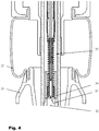
- Fig. 4 and Fig. 5 show in synopsis a further embodiment of the spring and damper unit with a two-stage pump, which is also driven by the by the compression and rebound of the vehicle changing distance between the articulation points and generates an increase in pressure in the damping and / or suspension medium.
- the two-stage pump is designed so that the second pump stage consisting essentially of pump piston 50, pump cylinder 51 and coil spring 52 is driven only when the compression stroke of the first stage of the pump is already fully utilized.
- This second stage operates on the same principle as the first stage consisting of pump cylinder 32 and pump piston 33, but operates only when the helical spring 35 (compression spring) of the first stage is partially compressed against the stop 36.
- the level of the body has lowered so far that the pump piston 33 is already pressed to block. This means that no suction can take place through the first pump stage and the spring and damper unit is not in its control position, from which the level control can start on the first few meters driven.
- the second pumping stage is installed, which serves as a "start-up aid" at an extremely low level and in any case ensures that the desired level can be approached.
- the pump piston 33 of the first stage is designed as a hollow cylinder and thus simultaneously in its inner part as a concentrically arranged pump cylinder 51.
- the concentrically formed pump piston 50 of the second stage is now arranged.
- the pump piston 50 is also driven via the plunger 34, but is on the latter with a coil spring 35 arranged in the concentric coil spring 35 between the plunger 34 and the pump piston 52 elastically connected to the plunger 34.
- the pump piston 50 is provided with a throttle check valve, not shown here, which serves as a suction valve.
- the two pump stages are thus space-saving connected in series and arranged concentrically within the hollow piston rod.
- the second stage is only flowed through by the pumped air.
- Fig. 6 shows the inventive design of a hinged between two points of articulation of the body and chassis of a vehicle two-stage pump a self-pumping spring and damper unit, as shown in detail in the previous embodiments, as a two-stage suspension pump 53 for use for an automatic and by the compression and rebound the vehicle driven pressure generation within any pressure supply system for a level control.
Landscapes
- Engineering & Computer Science (AREA)
- Mechanical Engineering (AREA)
- General Engineering & Computer Science (AREA)
- Vehicle Body Suspensions (AREA)
- Fluid-Damping Devices (AREA)
Claims (19)
- Unité de ressort et d'amortissement à auto-pompage (13), comprenant une régulation de niveau automatique pour châssis de véhicules, en particulier pour véhicules automobiles ou motocyclettes (1), qui est articulée à la carrosserie au niveau d'un point d'articulation (14) et au châssis au niveau de l'autre point d'articulation (15), et dont l'unité de ressort ou d'amortissement (13) présente au moins deux espaces de travail (16, 17, 18) pouvant être raccordés par un clapet d'étranglement (26, 27) pouvant être parcouru par l'écoulement, les espaces de travail contenant un fluide d'amortissement et/ou de suspension, qui, lors de la compression et de la détente des ressorts du véhicule, est échangé entre les espaces de travail (16, 17) de manière amortie par les clapets d'étranglement (26, 27), l'unité de ressort et d'amortissement (13) présentant au moins une pompe qui est entraînée par la variation de distance entre les points d'articulation (14, 15) provoquée par la compression et la détente des ressorts du véhicule, et qui génère une augmentation de pression dans le fluide d'amortissement et/ou de suspension de sorte que l'unité de ressort et d'amortissement (13), en cas de charge variable du véhicule, conserve un niveau fixe, la pompe étant constituée essentiellement de deux parties de pompe (32, 33) déplaçables l'une par rapport à l'autre et réduisant un espace de compression, dont une partie de pompe (33) est en liaison avec l'un des points d'articulation (14) et dont l'autre partie de pompe (32) est en liaison avec l'autre point d'articulation (15) de telle sorte que la variation de distance entre les points d'articulation (14, 15) lors de la compression et de la détente des ressorts du véhicule soit transmise en tant que course de compression à la distance entre les parties de pompe (32, 33), un élément de liaison élastique (35) étant disposé entre au moins une partie de pompe (33) et le point d'articulation associé (14), de telle sorte qu'il compense au moins en partie élastiquement la variation de distance entre les parties de pompe (32, 33) lors de la compression et de la détente des ressorts du véhicule, caractérisée en ce que l'unité de ressort et d'amortissement (13) est réalisée sous forme d'unité de ressort et d'amortissement pneumatique fonctionnant avec de l'air comprimé, au moins l'un des espaces de travail (18) remplis d'air comprimé étant limité au moins en partie par des parois mobiles en forme de soufflet roulant (22) et le soufflet roulant (22) roulant au moins en partie sur les contours de corps (23) à symétrie de révolution.
- Unité de ressort et d'amortissement à auto-pompage (13) selon la revendication 1, caractérisée en ce que la pompe est réalisée sous forme de pompe à piston avec un piston de pompe (33) raccordé au point d'articulation supérieur (14), qui peut être déplacé dans un cylindre de pompe (32) raccordé au point d'articulation inférieur (15), de telle sorte que l'augmentation de pression s'effectue pendant que l'unité de ressort et d'amortissement (13) se trouve dans l'étage de compression.
- Unité de ressort et d'amortissement à auto-pompage (13) selon la revendication 1 ou 2, caractérisée en ce que les deux espaces de travail (16, 17) sont séparés par un piston d'amortissement (25) pouvant être déplacé dans un cylindre d'amortissement (24), le cylindre d'amortissement (24) étant connecté à un point d'articulation (14) et le piston d'amortissement (25) étant connecté à l'autre point d'articulation (15) par le biais d'une tige de piston creuse (20), et la pompe à piston étant réalisée à l'intérieur de la tige de piston creuse (20) de telle sorte que la tige de piston creuse (20) serve de cylindre de pompe (32) dans lequel est disposé un piston de pompe (33) réalisé concentriquement par rapport à la tige de piston (20) et entraîné par le biais d'un poussoir (34) connecté au cylindre d'amortissement (24).
- Unité de ressort et d'amortissement à auto-pompage (13) selon les revendications 1 à 3, caractérisée en ce que l'élément de liaison élastique est réalisé sous forme de ressort hélicoïdal (35) disposé concentriquement dans la tige de piston creuse (20) entre le poussoir (34) et le piston (33) .
- Unité de ressort et d'amortissement à auto-pompage (13) selon les revendications 1 à 4, caractérisée en ce que le piston de pompe (33) présente un clapet antiretour d'étranglement (37) s'ouvrant vers l'un des espaces de travail (16).
- Unité de ressort et d'amortissement à auto-pompage (13) selon les revendications 1 à 5, caractérisée en ce que la pompe à piston est pourvue d'une butée (36) pour limiter la course du piston de pompe/la course de compression.
- Unité de ressort et d'amortissement à auto-pompage (13) selon les revendications 1 à 6, caractérisée en ce que l'espace de compression formé entre le piston de pompe (33) et le cylindre de pompe (32) peut être raccordé à l'air extérieur ou à un accumulateur de pression par le biais d'une (soupape d'entrée) (38) s'ouvrant vers l'espace de compression et sous forme de clapet antiretour d'étranglement.
- Unité de ressort et d'amortissement à auto-pompage (13) selon les revendications 1 à 7, caractérisée en ce que l'unité de ressort et d'amortissement (13) présente au moins un dispositif de sortie (39) qui est entraîné et/ou commandé par la variation de distance entre les points d'articulation (14, 15), provoquée par la compression et la détente des ressorts du véhicule et génère une réduction de pression dans le fluide d'amortissement et/ou de suspension de sorte que l'unité de ressort et d'amortissement (13) conserve un niveau fixe en cas de charge variable du véhicule.
- Unité de ressort et d'amortissement à auto-pompage (13) selon la revendication 8, caractérisée en ce que le dispositif de sortie (39) est réalisé sous forme de soupape de sortie avec un piston de sortie (40) pouvant être déplacé dans un cylindre de sortie (41) de telle sorte qu'un volume de sortie (42) se forme en tant que volume annulaire entre le piston de sortie (40) et le cylindre de sortie (41).
- Unité de ressort et d'amortissement à auto-pompage (13) selon la revendication 8 ou 9, caractérisée en ce que le piston de sortie (40) présente, du côté de l'entrée et du côté de la sortie, à chaque fois au moins une bague d'étanchéité (43, 44) pour réaliser l'étanchéité de l'espace annulaire/du volume annulaire (32) entre le piston de sortie (40) et le cylindre de sortie (41), et le cylindre de sortie (41) sert de siège d'étanchéité pour le piston de sortie (40), le dispositif de sortie (39) étant réalisé de telle sorte que l'ouverture du côté de l'entrée du volume de sortie (42) vers l'un des espaces de travail (16) et que l'ouverture du côté de la sortie du volume de sortie (42) vers l'air extérieur ou vers un accumulateur de pression s'effectue par le déplacement relatif entre le piston de sortie (40) et le cylindre de sortie (41).
- Unité de ressort et d'amortissement à auto-pompage (13) selon les revendications 8 à 10, caractérisée en ce que le piston de sortie (40) est formé par la tige de poussoir (34) et le cylindre de sortie (41) entoure la tige de poussoir (34) sous forme de manchon, en particulier sous forme de manchon au moins partiellement élargi.
- Unité de ressort et d'amortissement à auto-pompage (13) selon les revendications 8 à 11, caractérisée en ce que le cylindre de sortie (41) réalisé sous forme de manchon présente une butée élastique qui supporte le cylindre de sortie (41) par rapport à un déplacement du piston de sortie (40) au niveau de la tige de piston (20) ou de ses composants associés.
- Unité de ressort et d'amortissement à auto-pompage (13) selon la revendication 12, caractérisée en ce que la butée élastique est réalisée sous forme de plaque de butée concentrique (46) entourant la tige de poussoir (34), laquelle est supportée avec un ressort hélicoïdal (45) sur le cylindre de sortie (41) réalisé sous forme de manchon.
- Unité de ressort et d'amortissement à auto-pompage (13) selon les revendications 1 à 13, caractérisée en ce que la variation de distance entre les parties de pompe (32, 33) lors de la compression et de la détente des ressorts du véhicule, c'est-à-dire la course de compression et la longueur du déplacement entre le piston de sortie (40) et le cylindre de sortie (41), peuvent être ajustées.
- Unité de ressort et d'amortissement à auto-pompage (13) selon les revendications 1 à 14, caractérisée en ce que l'unité de ressort et d'amortissement (13) présente une pompe à deux étages, qui est entraînée par la variation de distance entre les points d'articulation (14, 15) provoquée par la compression et la détente des ressorts du véhicule, et génère une augmentation de pression dans le fluide d'amortissement et/ou de suspension, la pompe à deux étages étant réalisée de telle sorte que le deuxième étage de pompe soit seulement entraîné lorsque la course de compression du premier étage de la pompe est déjà complètement exploitée.
- Unité de ressort et d'amortissement à auto-pompage (13) selon la revendication 15, caractérisée en ce que les deux étages de pompe sont montés en série et sont disposés concentriquement à l'intérieur de la tige de piston creuse (20).
- Unité de ressort et d'amortissement à auto-pompage (13) selon la revendication 15 ou 16, caractérisée en ce que le piston de pompe creux (33) du premier étage sert de cylindre de pompe (51) dans lequel est disposé le piston de pompe (50) du deuxième étage, réalisé concentriquement à la tige de piston (20) et entraîné et connecté de manière élastique au poussoir (34).
- Unité de ressort et d'amortissement à auto-pompage (13) selon les revendications 1 à 17, caractérisée en ce que les dimensions du ressort hélicoïdal (35) disposé entre le poussoir (34) et le piston (33) et/ou les dimensions du ressort hélicoïdal (45) sur le cylindre de sortie (41) réalisé sous forme de manchon ainsi que les dimensions des butées et des logements pour ces ressorts (35, 45) sont réalisées de telle sorte que ces derniers soient utilisés en tant qu'éléments de ressort supplémentaires pour augmenter la progression de l'unité de ressort et d'amortissement (13).
- Utilisation d'une pompe à un ou plusieurs étages d'une unité de ressort et d'amortissement à auto-pompage (13) selon les revendications 1 à 18, articulée entre deux points d'articulation (14, 15) à la carrosserie et au châssis d'un véhicule, pour générer automatiquement une pression entraînée par la compression et la détente des ressorts du véhicule à l'intérieur d'une installation d'alimentation en pression pour une régulation de niveau.
Applications Claiming Priority (2)
| Application Number | Priority Date | Filing Date | Title |
|---|---|---|---|
| DE102006055757A DE102006055757B4 (de) | 2006-11-25 | 2006-11-25 | Selbstpumpende Niveauregulierung |
| PCT/EP2007/060996 WO2008061849A1 (fr) | 2006-11-25 | 2007-10-16 | Régulation de niveau à autopompage |
Publications (2)
| Publication Number | Publication Date |
|---|---|
| EP2097279A1 EP2097279A1 (fr) | 2009-09-09 |
| EP2097279B1 true EP2097279B1 (fr) | 2018-07-25 |
Family
ID=38962808
Family Applications (1)
| Application Number | Title | Priority Date | Filing Date |
|---|---|---|---|
| EP07821363.4A Not-in-force EP2097279B1 (fr) | 2006-11-25 | 2007-10-16 | Regulation de niveau a autopompage |
Country Status (4)
| Country | Link |
|---|---|
| US (1) | US8215620B2 (fr) |
| EP (1) | EP2097279B1 (fr) |
| DE (1) | DE102006055757B4 (fr) |
| WO (1) | WO2008061849A1 (fr) |
Cited By (1)
| Publication number | Priority date | Publication date | Assignee | Title |
|---|---|---|---|---|
| US12006998B2 (en) | 2020-02-17 | 2024-06-11 | Fm Energie Gmbh & Co. Kg | Adaptive tuned mass damper for damping low excitation frequencies |
Families Citing this family (13)
| Publication number | Priority date | Publication date | Assignee | Title |
|---|---|---|---|---|
| CA2730255A1 (fr) * | 2008-07-09 | 2010-01-14 | Firestone Industrial Products Company, Llc | Ressort a gaz, ensemble amortisseur a gaz et procede associe |
| AU2009268503B2 (en) * | 2008-07-09 | 2014-05-08 | Firestone Industrial Products Company, Llc | Gas spring and gas damper assembly and method |
| BR112014007999A2 (pt) | 2011-10-05 | 2017-04-11 | Firestone Ind Products Co Llc | conjunto e método do amortecedor de gás e mola de gás |
| DE102012200388A1 (de) * | 2011-10-06 | 2013-04-11 | Continental Teves Ag & Co. Ohg | Luftfederdeckel mit zuschaltbarem Luftvolumen |
| DE102012214569B3 (de) * | 2012-08-16 | 2013-10-31 | Ford Global Technologies, Llc | Luftfeder- und Dämpfereinheit mit Höhenverstellung |
| DE102013215360B4 (de) | 2012-09-10 | 2015-09-10 | Ford Global Technologies, Llc | Höhenverstellvorrichtung für Fahrzeuge mit Luftfeder und Schwingungsdämpfer |
| JP6012449B2 (ja) * | 2012-12-14 | 2016-10-25 | 株式会社ショーワ | 自動二輪車の車高調整装置 |
| FR3025746B1 (fr) * | 2014-09-16 | 2016-11-04 | Renault Sa | "jambe de force comportant un ressort pneumatique dont un piston est en appui sur l'extremite d'un corps d'amortisseur" |
| JP6407073B2 (ja) * | 2015-03-20 | 2018-10-17 | 株式会社ショーワ | 車高調整装置 |
| DE102016218787A1 (de) * | 2016-09-29 | 2018-03-29 | Bayerische Motoren Werke Aktiengesellschaft | Motorrad mit fluidbetätigter Absenkvorrichtung |
| JP6955419B2 (ja) * | 2017-10-16 | 2021-10-27 | 川崎重工業株式会社 | 自動二輪車 |
| DE102018212109A1 (de) * | 2018-07-20 | 2020-01-23 | Bayerische Motoren Werke Aktiengesellschaft | Höhenverstellbare Federanordnung für ein Fahrzeug |
| DE102023205524B3 (de) | 2023-06-14 | 2024-07-04 | Zf Friedrichshafen Ag | Druckluftversorgungseinrichtung |
Family Cites Families (22)
| Publication number | Priority date | Publication date | Assignee | Title |
|---|---|---|---|---|
| DE350851C (de) | 1920-04-27 | 1922-03-27 | Otto John Eisele | Federndes Rad |
| DE1209891B (de) * | 1961-05-09 | 1966-01-27 | David Alan Avner | Hydropneumatische Abfederung |
| DE3004307C2 (de) * | 1980-02-06 | 1984-06-07 | Boge Gmbh, 5208 Eitorf | Selbstpumpendes hydropneumatisches Teleskop-Feder-Dämpferelement mit innerer Niveauregelung |
| US4578950A (en) | 1981-11-23 | 1986-04-01 | Zorro Ruben | Double-acting rotary mechanism for combustion engines and the like |
| DE3306393C1 (de) * | 1983-02-24 | 1984-07-19 | Boge Gmbh, 5208 Eitorf | Selbstpumpendes hydropneumatisches Federbein mit innerer Niveauregelung |
| ES533297A0 (es) * | 1983-06-29 | 1985-03-01 | Boge Gmbh | Amortiguador hidraulico regulable |
| DE3502851C2 (de) * | 1983-08-06 | 1996-07-11 | Volkswagen Ag | Selbstpumpendes hydropneumatisches Teleskop-Feder-Dämpferelement |
| NL8800882A (nl) * | 1988-04-06 | 1989-11-01 | Koni Bv | Tweepijpsschokdemper. |
| WO1992016772A2 (fr) * | 1991-03-13 | 1992-10-01 | Alfred Teves Gmbh | Amortisseur bitube |
| DE4401770A1 (de) * | 1994-01-24 | 1995-08-03 | Fichtel & Sachs Ag | Selbstpumpendes Ferderbein mit Niveauregelung |
| JP2952149B2 (ja) * | 1994-02-21 | 1999-09-20 | トヨタ自動車株式会社 | ハイドロニューマチックシリンダ |
| JP2985707B2 (ja) * | 1995-01-31 | 1999-12-06 | トヨタ自動車株式会社 | セルフポンピング式ショックアブソーバ |
| US5797594A (en) * | 1995-07-22 | 1998-08-25 | Tokico, Ltd. | Hydraulic shock absorber |
| DE19529389C2 (de) * | 1995-08-10 | 1998-11-19 | Mannesmann Sachs Ag | Selbstpumpendes hydropneumatisches Federbein mit innerer Niveauregulierung |
| DE19547356A1 (de) | 1995-12-19 | 1997-06-26 | Vifor Int Ag | Adsorbens für Phosphat aus wäßrigem Medium, dessen Herstellung und Verwendung |
| DE19547536C2 (de) * | 1995-12-20 | 1999-12-09 | Mannesmann Sachs Ag | Selbstpumpendes hydropneumatisches Federbein mit innerer Niveauregulierung |
| DE19857595C2 (de) * | 1997-12-18 | 2003-06-26 | Zf Sachs Ag | Selbstpumpendes hydropneumatisches Federbein mit innerer Niveauregelung |
| DE19855229A1 (de) * | 1998-02-06 | 1999-08-12 | Hoheisel Hardy Dipl Oek | Federung |
| DE19838728C1 (de) * | 1998-08-26 | 1999-12-02 | Mannesmann Sachs Ag | Selbstpumpendes hydropneumatisches Federbein mit innerer Niveauregulierung |
| DE50010763D1 (de) * | 1999-08-24 | 2005-08-25 | Contitech Luftfedersyst Gmbh | Feder-dämpfersystem mit differenzrollbalg |
| US6547224B2 (en) * | 2001-04-12 | 2003-04-15 | Delphi Technologies, Inc. | Pneumatic self leveling suspension damper |
| DE102004021586B4 (de) | 2004-05-03 | 2010-09-23 | Continental Aktiengesellschaft | Luftfeder |
-
2006
- 2006-11-25 DE DE102006055757A patent/DE102006055757B4/de not_active Expired - Fee Related
-
2007
- 2007-10-16 WO PCT/EP2007/060996 patent/WO2008061849A1/fr not_active Ceased
- 2007-10-16 US US12/516,285 patent/US8215620B2/en not_active Expired - Fee Related
- 2007-10-16 EP EP07821363.4A patent/EP2097279B1/fr not_active Not-in-force
Non-Patent Citations (1)
| Title |
|---|
| None * |
Cited By (1)
| Publication number | Priority date | Publication date | Assignee | Title |
|---|---|---|---|---|
| US12006998B2 (en) | 2020-02-17 | 2024-06-11 | Fm Energie Gmbh & Co. Kg | Adaptive tuned mass damper for damping low excitation frequencies |
Also Published As
| Publication number | Publication date |
|---|---|
| DE102006055757B4 (de) | 2012-03-15 |
| DE102006055757A1 (de) | 2008-05-29 |
| WO2008061849A1 (fr) | 2008-05-29 |
| US20100065994A1 (en) | 2010-03-18 |
| EP2097279A1 (fr) | 2009-09-09 |
| US8215620B2 (en) | 2012-07-10 |
Similar Documents
| Publication | Publication Date | Title |
|---|---|---|
| EP2097279B1 (fr) | Regulation de niveau a autopompage | |
| DE102013215360B4 (de) | Höhenverstellvorrichtung für Fahrzeuge mit Luftfeder und Schwingungsdämpfer | |
| DE102012214569B3 (de) | Luftfeder- und Dämpfereinheit mit Höhenverstellung | |
| DE69931859T2 (de) | Fahrzeugaufhängungsvorrichtung | |
| EP2763863B1 (fr) | Suspension de roue de véhicule pourvue d'un amortisseur de vibrations hydraulique | |
| DE69802569T2 (de) | Aufhängungseinrichtung | |
| DE19721053C2 (de) | Hydraulischer Schwingungsdämpfer | |
| EP3700764B1 (fr) | Système amortisseur à ressort, à constante de rappel variable | |
| EP2085638B1 (fr) | Amortisseur à gaz sous pression | |
| DE10221833B4 (de) | Selbstpumpendes hydropneumatisches Federbein | |
| DE112013004595B4 (de) | Aufhängungsvorrichtung | |
| DE112012004573T5 (de) | Energie gewinnende passive und aktive Aufhängung | |
| DE3914385C2 (fr) | ||
| DE10139861B4 (de) | Radaufhängung eines Kraftfahrzeugs | |
| DE102007020118A1 (de) | Selbstpumpendes hydropneumatisches Federbein mit innerer Niveauregelung | |
| DE19857595A1 (de) | Selbstpumpendes hydropneumatisches Federbein mit innerer Niveauregelung | |
| DE19505711A1 (de) | Hydropneumatischer Stoßdämpfer | |
| DE19704189C2 (de) | Selbstpumpendes hydropneumatisches Federbein mit innerer Niveauregelung | |
| DE102011085233B4 (de) | Vorrichtung zur Höhenverstellung eines Fahrzeugaufbaus | |
| DE102006025826B4 (de) | Selbstpumpendes hydropneumatisches Federbein | |
| DE102013206122B4 (de) | Vorrichtung zur Höhenverstellung eines Fahrzeugaufbaus | |
| DE102012221666B4 (de) | Vorrichtung zur Höhenverstellung eines Fahrzeugaufbaus | |
| DE102021202624B4 (de) | Dämpfer mit reservoir | |
| EP1584502B1 (fr) | Dispositif de suspension et d'amortissement pour véhicules motorisés | |
| DE102006013832A1 (de) | Luftfeder- und Dämpfereinheit mit druckentlasteter Rollfalte |
Legal Events
| Date | Code | Title | Description |
|---|---|---|---|
| PUAI | Public reference made under article 153(3) epc to a published international application that has entered the european phase |
Free format text: ORIGINAL CODE: 0009012 |
|
| 17P | Request for examination filed |
Effective date: 20090625 |
|
| AK | Designated contracting states |
Kind code of ref document: A1 Designated state(s): AT BE BG CH CY CZ DE DK EE ES FI FR GB GR HU IE IS IT LI LT LU LV MC MT NL PL PT RO SE SI SK TR |
|
| DAX | Request for extension of the european patent (deleted) | ||
| RAP1 | Party data changed (applicant data changed or rights of an application transferred) |
Owner name: CONTINENTAL TEVES AG & CO. OHG |
|
| 17Q | First examination report despatched |
Effective date: 20121127 |
|
| GRAP | Despatch of communication of intention to grant a patent |
Free format text: ORIGINAL CODE: EPIDOSNIGR1 |
|
| RIC1 | Information provided on ipc code assigned before grant |
Ipc: B62K 25/04 20060101ALI20180306BHEP Ipc: F16F 9/04 20060101ALI20180306BHEP Ipc: B60G 17/044 20060101AFI20180306BHEP |
|
| INTG | Intention to grant announced |
Effective date: 20180319 |
|
| GRAS | Grant fee paid |
Free format text: ORIGINAL CODE: EPIDOSNIGR3 |
|
| GRAA | (expected) grant |
Free format text: ORIGINAL CODE: 0009210 |
|
| AK | Designated contracting states |
Kind code of ref document: B1 Designated state(s): AT BE BG CH CY CZ DE DK EE ES FI FR GB GR HU IE IS IT LI LT LU LV MC MT NL PL PT RO SE SI SK TR |
|
| REG | Reference to a national code |
Ref country code: GB Ref legal event code: FG4D Free format text: NOT ENGLISH |
|
| REG | Reference to a national code |
Ref country code: CH Ref legal event code: EP |
|
| REG | Reference to a national code |
Ref country code: AT Ref legal event code: REF Ref document number: 1021358 Country of ref document: AT Kind code of ref document: T Effective date: 20180815 |
|
| REG | Reference to a national code |
Ref country code: DE Ref legal event code: R096 Ref document number: 502007016306 Country of ref document: DE |
|
| REG | Reference to a national code |
Ref country code: IE Ref legal event code: FG4D Free format text: LANGUAGE OF EP DOCUMENT: GERMAN |
|
| RAP2 | Party data changed (patent owner data changed or rights of a patent transferred) |
Owner name: CONTINENTAL TEVES AG & CO. OHG |
|
| REG | Reference to a national code |
Ref country code: FR Ref legal event code: PLFP Year of fee payment: 12 |
|
| REG | Reference to a national code |
Ref country code: NL Ref legal event code: MP Effective date: 20180725 |
|
| REG | Reference to a national code |
Ref country code: LT Ref legal event code: MG4D |
|
| PG25 | Lapsed in a contracting state [announced via postgrant information from national office to epo] |
Ref country code: NL Free format text: LAPSE BECAUSE OF FAILURE TO SUBMIT A TRANSLATION OF THE DESCRIPTION OR TO PAY THE FEE WITHIN THE PRESCRIBED TIME-LIMIT Effective date: 20180725 |
|
| PG25 | Lapsed in a contracting state [announced via postgrant information from national office to epo] |
Ref country code: GR Free format text: LAPSE BECAUSE OF FAILURE TO SUBMIT A TRANSLATION OF THE DESCRIPTION OR TO PAY THE FEE WITHIN THE PRESCRIBED TIME-LIMIT Effective date: 20181026 Ref country code: IS Free format text: LAPSE BECAUSE OF FAILURE TO SUBMIT A TRANSLATION OF THE DESCRIPTION OR TO PAY THE FEE WITHIN THE PRESCRIBED TIME-LIMIT Effective date: 20181125 Ref country code: BG Free format text: LAPSE BECAUSE OF FAILURE TO SUBMIT A TRANSLATION OF THE DESCRIPTION OR TO PAY THE FEE WITHIN THE PRESCRIBED TIME-LIMIT Effective date: 20181025 Ref country code: FI Free format text: LAPSE BECAUSE OF FAILURE TO SUBMIT A TRANSLATION OF THE DESCRIPTION OR TO PAY THE FEE WITHIN THE PRESCRIBED TIME-LIMIT Effective date: 20180725 Ref country code: LT Free format text: LAPSE BECAUSE OF FAILURE TO SUBMIT A TRANSLATION OF THE DESCRIPTION OR TO PAY THE FEE WITHIN THE PRESCRIBED TIME-LIMIT Effective date: 20180725 Ref country code: PL Free format text: LAPSE BECAUSE OF FAILURE TO SUBMIT A TRANSLATION OF THE DESCRIPTION OR TO PAY THE FEE WITHIN THE PRESCRIBED TIME-LIMIT Effective date: 20180725 Ref country code: SE Free format text: LAPSE BECAUSE OF FAILURE TO SUBMIT A TRANSLATION OF THE DESCRIPTION OR TO PAY THE FEE WITHIN THE PRESCRIBED TIME-LIMIT Effective date: 20180725 |
|
| PG25 | Lapsed in a contracting state [announced via postgrant information from national office to epo] |
Ref country code: ES Free format text: LAPSE BECAUSE OF FAILURE TO SUBMIT A TRANSLATION OF THE DESCRIPTION OR TO PAY THE FEE WITHIN THE PRESCRIBED TIME-LIMIT Effective date: 20180725 Ref country code: LV Free format text: LAPSE BECAUSE OF FAILURE TO SUBMIT A TRANSLATION OF THE DESCRIPTION OR TO PAY THE FEE WITHIN THE PRESCRIBED TIME-LIMIT Effective date: 20180725 |
|
| REG | Reference to a national code |
Ref country code: DE Ref legal event code: R097 Ref document number: 502007016306 Country of ref document: DE |
|
| PG25 | Lapsed in a contracting state [announced via postgrant information from national office to epo] |
Ref country code: EE Free format text: LAPSE BECAUSE OF FAILURE TO SUBMIT A TRANSLATION OF THE DESCRIPTION OR TO PAY THE FEE WITHIN THE PRESCRIBED TIME-LIMIT Effective date: 20180725 Ref country code: RO Free format text: LAPSE BECAUSE OF FAILURE TO SUBMIT A TRANSLATION OF THE DESCRIPTION OR TO PAY THE FEE WITHIN THE PRESCRIBED TIME-LIMIT Effective date: 20180725 Ref country code: IT Free format text: LAPSE BECAUSE OF FAILURE TO SUBMIT A TRANSLATION OF THE DESCRIPTION OR TO PAY THE FEE WITHIN THE PRESCRIBED TIME-LIMIT Effective date: 20180725 Ref country code: CZ Free format text: LAPSE BECAUSE OF FAILURE TO SUBMIT A TRANSLATION OF THE DESCRIPTION OR TO PAY THE FEE WITHIN THE PRESCRIBED TIME-LIMIT Effective date: 20180725 |
|
| PG25 | Lapsed in a contracting state [announced via postgrant information from national office to epo] |
Ref country code: DK Free format text: LAPSE BECAUSE OF FAILURE TO SUBMIT A TRANSLATION OF THE DESCRIPTION OR TO PAY THE FEE WITHIN THE PRESCRIBED TIME-LIMIT Effective date: 20180725 Ref country code: SK Free format text: LAPSE BECAUSE OF FAILURE TO SUBMIT A TRANSLATION OF THE DESCRIPTION OR TO PAY THE FEE WITHIN THE PRESCRIBED TIME-LIMIT Effective date: 20180725 |
|
| PLBE | No opposition filed within time limit |
Free format text: ORIGINAL CODE: 0009261 |
|
| REG | Reference to a national code |
Ref country code: CH Ref legal event code: PL |
|
| STAA | Information on the status of an ep patent application or granted ep patent |
Free format text: STATUS: NO OPPOSITION FILED WITHIN TIME LIMIT |
|
| GBPC | Gb: european patent ceased through non-payment of renewal fee |
Effective date: 20181025 |
|
| REG | Reference to a national code |
Ref country code: BE Ref legal event code: MM Effective date: 20181031 |
|
| PG25 | Lapsed in a contracting state [announced via postgrant information from national office to epo] |
Ref country code: MC Free format text: LAPSE BECAUSE OF FAILURE TO SUBMIT A TRANSLATION OF THE DESCRIPTION OR TO PAY THE FEE WITHIN THE PRESCRIBED TIME-LIMIT Effective date: 20180725 Ref country code: LU Free format text: LAPSE BECAUSE OF NON-PAYMENT OF DUE FEES Effective date: 20181016 |
|
| 26N | No opposition filed |
Effective date: 20190426 |
|
| REG | Reference to a national code |
Ref country code: IE Ref legal event code: MM4A |
|
| PG25 | Lapsed in a contracting state [announced via postgrant information from national office to epo] |
Ref country code: BE Free format text: LAPSE BECAUSE OF NON-PAYMENT OF DUE FEES Effective date: 20181031 Ref country code: CH Free format text: LAPSE BECAUSE OF NON-PAYMENT OF DUE FEES Effective date: 20181031 Ref country code: LI Free format text: LAPSE BECAUSE OF NON-PAYMENT OF DUE FEES Effective date: 20181031 Ref country code: SI Free format text: LAPSE BECAUSE OF FAILURE TO SUBMIT A TRANSLATION OF THE DESCRIPTION OR TO PAY THE FEE WITHIN THE PRESCRIBED TIME-LIMIT Effective date: 20180725 |
|
| PG25 | Lapsed in a contracting state [announced via postgrant information from national office to epo] |
Ref country code: IE Free format text: LAPSE BECAUSE OF NON-PAYMENT OF DUE FEES Effective date: 20181016 Ref country code: GB Free format text: LAPSE BECAUSE OF NON-PAYMENT OF DUE FEES Effective date: 20181025 |
|
| REG | Reference to a national code |
Ref country code: AT Ref legal event code: MM01 Ref document number: 1021358 Country of ref document: AT Kind code of ref document: T Effective date: 20181016 |
|
| PG25 | Lapsed in a contracting state [announced via postgrant information from national office to epo] |
Ref country code: AT Free format text: LAPSE BECAUSE OF NON-PAYMENT OF DUE FEES Effective date: 20181016 Ref country code: MT Free format text: LAPSE BECAUSE OF FAILURE TO SUBMIT A TRANSLATION OF THE DESCRIPTION OR TO PAY THE FEE WITHIN THE PRESCRIBED TIME-LIMIT Effective date: 20180725 |
|
| PGFP | Annual fee paid to national office [announced via postgrant information from national office to epo] |
Ref country code: FR Payment date: 20191028 Year of fee payment: 13 |
|
| PG25 | Lapsed in a contracting state [announced via postgrant information from national office to epo] |
Ref country code: TR Free format text: LAPSE BECAUSE OF FAILURE TO SUBMIT A TRANSLATION OF THE DESCRIPTION OR TO PAY THE FEE WITHIN THE PRESCRIBED TIME-LIMIT Effective date: 20180725 |
|
| PG25 | Lapsed in a contracting state [announced via postgrant information from national office to epo] |
Ref country code: PT Free format text: LAPSE BECAUSE OF FAILURE TO SUBMIT A TRANSLATION OF THE DESCRIPTION OR TO PAY THE FEE WITHIN THE PRESCRIBED TIME-LIMIT Effective date: 20180725 |
|
| PG25 | Lapsed in a contracting state [announced via postgrant information from national office to epo] |
Ref country code: CY Free format text: LAPSE BECAUSE OF FAILURE TO SUBMIT A TRANSLATION OF THE DESCRIPTION OR TO PAY THE FEE WITHIN THE PRESCRIBED TIME-LIMIT Effective date: 20180725 Ref country code: HU Free format text: LAPSE BECAUSE OF FAILURE TO SUBMIT A TRANSLATION OF THE DESCRIPTION OR TO PAY THE FEE WITHIN THE PRESCRIBED TIME-LIMIT; INVALID AB INITIO Effective date: 20071016 |
|
| PGFP | Annual fee paid to national office [announced via postgrant information from national office to epo] |
Ref country code: DE Payment date: 20201216 Year of fee payment: 14 |
|
| PG25 | Lapsed in a contracting state [announced via postgrant information from national office to epo] |
Ref country code: FR Free format text: LAPSE BECAUSE OF NON-PAYMENT OF DUE FEES Effective date: 20201031 |
|
| REG | Reference to a national code |
Ref country code: DE Ref legal event code: R119 Ref document number: 502007016306 Country of ref document: DE |
|
| PG25 | Lapsed in a contracting state [announced via postgrant information from national office to epo] |
Ref country code: DE Free format text: LAPSE BECAUSE OF NON-PAYMENT OF DUE FEES Effective date: 20220503 |