EP2097595B1 - Étai télescopique - Google Patents
Étai télescopique Download PDFInfo
- Publication number
- EP2097595B1 EP2097595B1 EP07846387.4A EP07846387A EP2097595B1 EP 2097595 B1 EP2097595 B1 EP 2097595B1 EP 07846387 A EP07846387 A EP 07846387A EP 2097595 B1 EP2097595 B1 EP 2097595B1
- Authority
- EP
- European Patent Office
- Prior art keywords
- inner tube
- outer tube
- prop
- connecting element
- tube
- Prior art date
- Legal status (The legal status is an assumption and is not a legal conclusion. Google has not performed a legal analysis and makes no representation as to the accuracy of the status listed.)
- Not-in-force
Links
Images
Classifications
-
- E—FIXED CONSTRUCTIONS
- E04—BUILDING
- E04G—SCAFFOLDING; FORMS; SHUTTERING; BUILDING IMPLEMENTS OR AIDS, OR THEIR USE; HANDLING BUILDING MATERIALS ON THE SITE; REPAIRING, BREAKING-UP OR OTHER WORK ON EXISTING BUILDINGS
- E04G25/00—Shores or struts; Chocks
-
- E—FIXED CONSTRUCTIONS
- E04—BUILDING
- E04G—SCAFFOLDING; FORMS; SHUTTERING; BUILDING IMPLEMENTS OR AIDS, OR THEIR USE; HANDLING BUILDING MATERIALS ON THE SITE; REPAIRING, BREAKING-UP OR OTHER WORK ON EXISTING BUILDINGS
- E04G11/00—Forms, shutterings, or falsework for making walls, floors, ceilings, or roofs
- E04G11/36—Forms, shutterings, or falsework for making walls, floors, ceilings, or roofs for floors, ceilings, or roofs of plane or curved surfaces end formpanels for floor shutterings
- E04G11/48—Supporting structures for shutterings or frames for floors or roofs
-
- E—FIXED CONSTRUCTIONS
- E04—BUILDING
- E04G—SCAFFOLDING; FORMS; SHUTTERING; BUILDING IMPLEMENTS OR AIDS, OR THEIR USE; HANDLING BUILDING MATERIALS ON THE SITE; REPAIRING, BREAKING-UP OR OTHER WORK ON EXISTING BUILDINGS
- E04G25/00—Shores or struts; Chocks
- E04G25/04—Shores or struts; Chocks telescopic
-
- E—FIXED CONSTRUCTIONS
- E04—BUILDING
- E04G—SCAFFOLDING; FORMS; SHUTTERING; BUILDING IMPLEMENTS OR AIDS, OR THEIR USE; HANDLING BUILDING MATERIALS ON THE SITE; REPAIRING, BREAKING-UP OR OTHER WORK ON EXISTING BUILDINGS
- E04G7/00—Connections between parts of the scaffold
- E04G7/02—Connections between parts of the scaffold with separate coupling elements
- E04G7/06—Stiff scaffolding clamps for connecting scaffold members of common shape
- E04G7/22—Stiff scaffolding clamps for connecting scaffold members of common shape for scaffold members in end-to-side relation
Definitions
- the invention relates to a telescoping prop with an outer tube, an inner tube displaceable in the outer tube and a connection element for fastening a stiffener on the inner tube having the features of the preamble of claim 1.
- Telescopic supports are known, they are used, for example, for setting up slab formwork or scaffolding.
- Known telescopic props have an outer tube and an inner tube, which is displaceable for length or height adjustment in the outer tube. Because of the displaceability of the inner tube in the outer tube, the props are referred to as telescopic.
- the inner tube can be fixed in steps or steplessly in the outer tube.
- stiffeners can, for example Struts or frames, the frames are usually formed as a triangular braced grid frame.
- the outer tubes of known, telescoping props for example, T-grooves or T-shaped or mushroom-shaped ribs in cross-section.
- the T-slots can be fitted with hammer-head bolts or plate-shaped nuts, also known as T-slot nuts or T-slot nuts.
- T-slot nuts or T-slot nuts For attachment to T-shaped or mushroom-shaped ribs brackets are known.
- the T-slots or T-shaped or mushroom-shaped ribs can also generally be understood as a fastening device for stiffeners.
- a telescopic prop of the type described above discloses the European patent EP 0 665 348 B1 ,
- the well-known prop has a cross-sectionally octagonal outer tube and a telescoping in this, smooth-walled inner tube.
- the inner tube has transverse holes for length and height adjustment of the prop, which are penetrated by a mandrel of a nut.
- the octagonal outer cross-section in the cross section has four, each offset by 90 ° to each other T-slots for attachment of stiffeners with, for example, hammer head screws or plate-shaped, can be used in the T-nuts.
- the prop is kinky at the transition from the outer tube to the inner tube.
- a stiffening on the inner tube is desirable.
- an outer diameter of the outer tube is larger than an outer diameter of the inner tube.
- the clear distance of the outer tubes of two parallel spaced parallel to each other props is smaller on the outer tubes than on the inner tubes. If the stiffeners are obliquely arranged struts, the distance difference can possibly be compensated. If frames are used to brace the brackets, it is not easy to compensate for the distance.
- the said European patent EP 0 553 665 B1 to form the outer tube with mushroom-shaped in cross-section, hollow, longitudinally extending bulges instead of T-shaped or mushroom-shaped ribs as fastening devices.
- the inner tube has mushroom-shaped ribs in cross section, which are located in the hollow, mushroom-shaped bulges of the outer tube. Lateral grooves of the mushroom-shaped protrusions of the outer tube and the mushroom-shaped ribs of the inner tube are arranged at the same radial distance from an imaginary axis of the prop.
- the attachment of the stiffener is carried out with a clip which engages in the lateral grooves of the mushroom-shaped bulges of the outer tube or the mushroom-shaped ribs of the inner tube.
- the distance of the lateral grooves of the imaginary axis of the prop in the inner tube and the outer tube is the same, the distance of the lateral grooves of the mushroom-shaped bulges of the outer tube and the mushroom-shaped ribs of the inner tube of two spaced apart parallel to each other props is the same. It can thereby connect the outer and the inner tube of the two spaced parallel parallel props with the same stiffeners.
- the patent application GB 2 407 842 A proposes an openable, in front view U-shaped sleeve, which is placed on the inner tube of a telescoping prop and the two flaps, which are pivotally mounted on the sleeve, closable to the inner tube of the prop and closable by means of a screw on the inner tube , Noses engage in a thread of the inner tube and thus secure the sleeve in axial Direction on the inner tube.
- the cuff has three T-slots for attachment of struts.
- GB 2 407 842 A discloses the features of the introductory part of claim 1.
- the utility model DE 20 2004 002 593 U1 discloses a sleeve which consists of an axially divided into two halves sleeve, which are pivotally connected to each other for attachment to an inner tube of a prop and connected with a screw and can be tensioned.
- the axially split sleeve has an internal thread that engages a thread of the inner tube of the prop.
- Each half of the sleeve has a half perforated disc forming a radial flange provided with recesses for attachment of stiffeners which are connected and keyed with through wedges.
- the object of the invention is to propose another possibility with which the inner tubes of two spaced apart parallel to each other, telescoping props with the same stiffener as the outer tubes of the props are connectable.
- This object is achieved by the features of claim 1.
- the inventive telescopic prop has an outer tube, an inner tube displaceable in the outer tube, and a detachably attached to the inner tube Connection element on. This may be, for example, one or more tension straps which can be laid around the inner tube and which are fastened or attachable to the connecting element.
- the outer tube of the prop and the connecting element have congruent and mutually aligned T-slots, T, L or mushroom-shaped ribs as means for attaching a stiffener.
- the device of the connecting element for fastening the stiffening is corresponding to the fastening device of the outer tube of the brace for the stiffening.
- correspondence is meant that the stiffener with the same connection means, so for example a hammer head screw or a clamp, both on the fastening means of the outer tube of the prop as well as on the fastening means of the connecting element can be fastened.
- the fastening device of the connecting element has the same cross-section as the fastening device of the outer tube. Furthermore, the fastening device for the stiffening of the connecting element according to the invention and the fastening device for the stiffening of the outer tube are aligned when the connecting element is fastened to the inner tube of the prop.
- the invention has the advantage that a stiffener can be attached at will to the outer tubes or inner tubes of two spaced parallel to each other props erected. Also, it is easily possible to have a stiffener that two or more longitudinally of the props from each other has spaced attachment points to attach with the connection element according to the invention on the inner tube and directly on the outer tube of the prop. With the connecting element according to the invention props can be connected to their inner tubes with the same stiffeners as on their outer tubes.
- An embodiment of the invention provides that the connecting element in the region of the fastening device has a cross-section matching the outer tube of the prop in the region of the fastening device.
- the fastening device of the connecting element has, as already stated above, the same cross-section as the fastening device of the outer tube of the prop. This reliably ensures that a stiffener, which is attachable to the outer tube of the prop, by means of the connecting element according to the invention also on the inner tube of the prop can be fastened.
- An embodiment of the invention provides that the connecting element as a whole, ie not only in the region of the fastening device, has a cross-section matching the outer tube of the prop.
- connection element according to the invention can be designed for example as a so-called “shoe”, which extends over a limited peripheral portion of not more than 180 ° and which is set and fixed from one side to the inner tube of the prop.
- An embodiment of the invention provides a connection element designed as an openable sleeve.
- the sleeve may, for example, have two halves extending in the circumferential direction over approximately 180 ° each and the opening for example by means of a hinge can be pivoted apart and together. With the sleeve, it is possible to continue a cross section of the outer tube substantially unchanged on the inner tube.
- An embodiment of the invention provides a positive locking element, which engages positively in a complementary connection device of the inner tube of the prop when connected to the inner tube connecting element.
- the form-fitting element may for example be a pin which engages in a hole of the inner tube of the prop.
- a nose is conceivable, which engages in a thread of the inner tube of the prop, if the inner tube has an external thread for length or height adjustment.
- a reversal, ie, a protruding from the inner tube outward, engaging in a complementary recess of the connecting element positive locking element is possible within the scope of this embodiment of the invention.
- the interlocking element holds the connecting element in the axial direction and / or in the circumferential direction on the inner tube of the prop. By the latter, it is possible to ensure an aligned alignment of the fastening device of the connecting element and the fastening device of the outer tube of the prop, provided that the inner tube in the outer tube rotatably and rotationally guided.
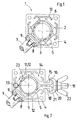
- telescopic prop 1 has an outer tube 2 and a displaceable in the outer tube 2 inner tube 3. Because of the displaceability of the two tubes 2, 3, the prop 1 is referred to as telescopic.
- the inner tube 3 is a cylindrical, smooth-walled tube at one end face of a front plate 4 is welded.
- the front plate 4 serves as a foot of the prop 1, for connecting the prop 1 with another prop 1 or for attachment of a head, not shown, for example, for attachment of a slab formwork, not shown on the prop 1.
- the inner tube 3 has a number of transversely continuous holes 5 which are axially mounted at preferably equal intervals.
- the inner tube 3 is made of steel, for example.
- the outer tube 2 is cylindrical inside for slidably receiving and guiding the inner tube 3 and octagonal outside. It has four T-slots 6 for attachment of stiffeners. Another, in particular larger number of T-slots is possible, for example, eight T-slots. As a result, the angular distances from T-slot to T-slot are smaller (not shown).
- a fragment of a frame 7 is shown as a stiffening element. With the Reference numeral 7 is actually designated an end of a pipe forming a cross member of the frame 7. The attachment takes place with engaging in the T-slots 6 hammer head screws 8.
- the frame 7 shown by way of example is a lattice frame with shoes 9 on both sides, which are recognized in the region of one of the T-slots 6 on the outer tube 2, wherein the shoes 9 edges 10th of the outer tube 2 laterally overlap the respective T-slot 6.
- the outer tube 2 is a profile tube with constant over its length cross section, which is made for example of steel or preferably an aluminum alloy. The preparation can be done for example by extrusion, rod drawing or continuous casting.
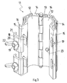
- connecting element 11 is formed as an openable sleeve.
- the connecting element 11 is divided in the longitudinal direction into two sleeve halves 12, each extending over approximately 180 ° in the circumferential direction.
- Each cuff half 12 may be referred to as a shoe by itself.
- the two sleeve halves 12 are formed as a hinge 13 and pivotally connected to each other for opening and closing.
- Inner sides of the sleeve halves 12 are cylindrical with the same radius as an outer side of the inner tube 3. How good in FIG.
- the T-slots 14 of the connecting element 11 are not only corresponding to the T-slots 6 of the outer tube 2, but they are congruent.
- the octagonal outline of the closed terminal 11 is congruent with the outline of the outer tube 2.
- the T-grooves 6, 14 of the outer tube 2 and the terminal member 11 may also generally as fastening means or means for fixing a stiffener such as Frame 7 are understood. Due to their design as T-grooves 6, 14, the fastening devices have undercuts.
- the sleeve halves 12 of the connecting element 11 have, at their longitudinal edges opposite the hinge 13, radially outward ribs 15 which are angled at 90 ° to the side at their free longitudinal edges.
- the ribs 15 are characterized in cross-section L-shaped, their outer edges are formed as bevels 16.
- the ribs 15 are provided with closed at both ends longitudinal slots 17 for the engagement of plate nuts 18.
- the plate nuts 18 have an approximately square shape in plan view, they have a center hole with internal thread into which a threaded bolt 19 is screwed. By a locking varnish, a spot weld, a plastic deformation or the like.
- the threaded bolt 19 are rotationally fixed with the plate nuts 18.
- a closing plate 20 is arranged, which has a center hole through which the threaded bolt 19 protrudes.
- the closing plate 20 is rectangular in plan view, its longitudinal edges are angled as a wing 21 obliquely outwards and in the direction of the connecting element 11 standing.
- the wings 21 have the same slope as the slopes 16 of the L-shaped ribs 15 of the collar halves 12 of the connection element 11.
- the wings 21 of the closing plates 20 engage over the ribs 15 at their bevels 16 as shown in FIG FIG. 2 you can see.
- the respective closing plate 20 With a screwed onto the threaded bolt 19 wing nut 22, the respective closing plate 20 can be tensioned inwards and keeps the connection element 11 closed, wherein it clamps the sleeve halves 12 to the L-shaped ribs 15 due to the inclination of the wings 21 and the bevels 16.
- the connection element 11 can be as in FIG. 2 to be clamped on the inner tube 3 of the prop 1, ie fasten.
- the connecting element 11 thus has, due to its design as an openable sleeve, the sleeve halves 12 are clamped together, a means for fixing to the inner tube 3 of the prop 1.
- Other closures for the Cuff such as wedges or toggle are possible (not shown).
- One of the two sleeve halves 12 of the connecting element 11 has a short, inwardly projecting pin, which forms a form-locking element 23.
- the connecting element 11 is attached to the inner tube 3 so that the pin forming the positive locking element 23 engages in one of the holes 5 of the inner tube 3.
- the hole 5 of the inner tube 3 forms a complementary connection means for the pin forming the positive locking element 23, in which the pin engages positively.
- the connecting element 11 is held in the axial direction, ie in its height, on the inner tube 3 of the prop 1.
- the positive-locking element 23 aligns the connecting element 11 in its angular position on the inner tube 3.
- the connecting element 11 Since the angular position of the outer tube 2 is specified with respect to the inner tube 3 via a special nut, not shown for length or height adjustment of the prop 1, the connecting element 11 is arranged congruent to the outer tube 2.
- the connecting element 11 allows the attachment of a stiffening element, which is fastened to the outer tube 2 of the prop 1, in the same way on the inner tube 3 of the prop 1.
- FIG. 2 is like in FIG. 1 a frame 7 shown as a stiffening element, which is fastened with a hammer head screw 8 in the T-groove 14 of the connecting element 11.
- the sleeve halves 12 of the connection element 11 are profile half tubes with a constant cross section over their length.
- the sleeve halves 12 are identical and assembled in mirror image at its hinge 13. They consist for example of steel or in particular of an aluminum alloy and are as well as the outer tube 2 of the prop 1 produced by extrusion or pultrusion.
Landscapes
- Engineering & Computer Science (AREA)
- Architecture (AREA)
- Mechanical Engineering (AREA)
- Civil Engineering (AREA)
- Structural Engineering (AREA)
- Mutual Connection Of Rods And Tubes (AREA)
Claims (4)
- Etai télescopique comprenant une tubulure extérieure (2) et une tubulure intérieure (3) apte à coulisser dans ladite tubulure extérieure (2), laquelle tubulure extérieure (2) comporte un dispositif (6) dévolu à la fixation d'un raidisseur (7) ; et un élément de rattachement (11), fixé amoviblement à la tubulure intérieure (3) dudit étai (1) et muni d'un dispositif (14) dévolu à la fixation dudit raidisseur (7), caractérisé par le fait que les dispositifs de fixation (14, 6) de l'élément de rattachement (11) et de la tubulure extérieure (2) de l'étai (1) sont pourvus de rainures en T, de nervures en T, en L ou en forme de têtes de champignons, coïncidentes et alignées les unes avec les autres.
- Etai selon la revendication 1, caractérisé par le fait que l'élément de rattachement (11) présente une section transversale concordant avec la tubulure extérieure (2) dudit étai (1).
- Etai selon la revendication 1 ou 2, caractérisé par le fait que l'élément de rattachement (11) est réalisé sous la forme d'un manchon pouvant être ouvert.
- Etai selon l'une des revendications 1 à 3, caractérisé par le fait que l'élément de rattachement (11) est doté d'un élément (23) d'assemblage par conformation conçu pour venir en prise, par concordance de formes, avec un dispositif complémentaire (5) de rattachement de la tubulure intérieure (3) dudit étai (1).
Applications Claiming Priority (2)
| Application Number | Priority Date | Filing Date | Title |
|---|---|---|---|
| DE200710001170 DE102007001170B3 (de) | 2007-01-05 | 2007-01-05 | Anschlusselement zur Befestigung einer Aussteifung an einem Innenrohr einer teleskopierbaren Baustütze und teleskopierbare Baustütze mit einem solchen Anschlusselement |
| PCT/DE2007/002184 WO2008080377A1 (fr) | 2007-01-05 | 2007-12-01 | Élément de raccordement pour fixer un renfort à un tube intérieur d'un étai télescopique, et étai télescopique pourvu d'un tel élément de raccordement |
Publications (2)
| Publication Number | Publication Date |
|---|---|
| EP2097595A1 EP2097595A1 (fr) | 2009-09-09 |
| EP2097595B1 true EP2097595B1 (fr) | 2016-06-29 |
Family
ID=39466043
Family Applications (1)
| Application Number | Title | Priority Date | Filing Date |
|---|---|---|---|
| EP07846387.4A Not-in-force EP2097595B1 (fr) | 2007-01-05 | 2007-12-01 | Étai télescopique |
Country Status (3)
| Country | Link |
|---|---|
| EP (1) | EP2097595B1 (fr) |
| DE (2) | DE102007001170B3 (fr) |
| WO (1) | WO2008080377A1 (fr) |
Families Citing this family (3)
| Publication number | Priority date | Publication date | Assignee | Title |
|---|---|---|---|---|
| DE102010027890A1 (de) | 2010-04-16 | 2011-12-01 | Harsco Infrastructure Services Gmbh | Mehrteiliges manschettenartiges Anschlusselement und teleskopierbares Vertikalrohr mit demselben |
| NO333028B1 (no) * | 2010-11-08 | 2013-02-18 | Alustar As | Fremgangsmate for a lase en baerekrans til en stillassoyle. |
| DE102013009401A1 (de) * | 2013-06-05 | 2014-12-11 | Roland Hörnstein GmbH & Co. KG | Hubstempel für Fahrzeughebebühnen |
Family Cites Families (6)
| Publication number | Priority date | Publication date | Assignee | Title |
|---|---|---|---|---|
| FR2324830A2 (fr) * | 1975-09-19 | 1977-04-15 | Self Lock Echafaudages | Echafaudage prefabrique |
| GB2262562B (en) * | 1991-12-20 | 1994-10-19 | Sgb Holdings Ltd | Improvements in or relating to a shoring system |
| DE4201958A1 (de) * | 1992-01-25 | 1993-08-05 | Peri Gmbh | Traggeruest |
| DE4400360A1 (de) * | 1994-01-08 | 1995-07-13 | Gerhard Dingler | Stütze |
| GB2407842B (en) * | 2003-11-07 | 2006-03-01 | Sgb Services Ltd | Shoring system comprising a scaffold clamp |
| DE202004002593U1 (de) * | 2004-02-19 | 2004-06-09 | Wilhelm Layher Vermögensverwaltungs-Gmbh | Anschlusselement für Verbindungsvorrichtungen für Gerüstelemente |
-
2007
- 2007-01-05 DE DE200710001170 patent/DE102007001170B3/de not_active Expired - Fee Related
- 2007-12-01 EP EP07846387.4A patent/EP2097595B1/fr not_active Not-in-force
- 2007-12-01 WO PCT/DE2007/002184 patent/WO2008080377A1/fr not_active Ceased
- 2007-12-01 DE DE112007003383T patent/DE112007003383A5/de not_active Withdrawn
Also Published As
| Publication number | Publication date |
|---|---|
| DE112007003383A5 (de) | 2009-12-03 |
| DE102007001170B3 (de) | 2008-07-03 |
| WO2008080377A1 (fr) | 2008-07-10 |
| EP2097595A1 (fr) | 2009-09-09 |
Similar Documents
| Publication | Publication Date | Title |
|---|---|---|
| EP3721028B1 (fr) | Équipement comprenant un dispositif anti-soulèvement et procédé pour empêcher un plancher d'échafaudage de se soulever | |
| DE2704398C3 (de) | Aus Ständern und Riegeln zusammensetzbares Gerüst | |
| EP3230537B1 (fr) | Cadre de treillis, support de charpente modulaire et structure de pontage et/ou de support | |
| DE3641349C5 (de) | Baustütze | |
| WO2016026812A1 (fr) | Dispositif d'ancrage d'un coffrage pour mur en béton, élément de coffrage et procédé de montage d'un dispositif d'ancrage | |
| EP0553665B1 (fr) | Echafaudage | |
| DE2045456A1 (de) | Kupplung fur Armiereisen oder der gleichen | |
| EP2097595B1 (fr) | Étai télescopique | |
| EP0625622A1 (fr) | Etai télescopique | |
| EP3402938B1 (fr) | Poutre en treillis modulaire | |
| DE8914503U1 (de) | Geländer | |
| DE3200939A1 (de) | Deckentische zum giessen von betondecken | |
| DE102010027890A1 (de) | Mehrteiliges manschettenartiges Anschlusselement und teleskopierbares Vertikalrohr mit demselben | |
| EP0594948B1 (fr) | Serre-éclisses pour superstructures de toits | |
| EP1961886B1 (fr) | Support de profil en U d'une toiture, d'un hall, d'une tribune, d'un escalier, d'un échafaudage ou d'un podium | |
| AT396278B (de) | Stuetzvorrichtung | |
| EP2333200A1 (fr) | Elément de raccordement et tuyau vertical télescopable en étant équipé | |
| EP3983626B1 (fr) | Poteaux d'appui et garde-corps à serrage rapide de conception modulaire | |
| DE3642846C2 (fr) | ||
| EP0317695B1 (fr) | Echafaudage métallique pour le bâtiment | |
| DE29813088U1 (de) | Montagevorrichtung | |
| DE2515166C2 (de) | Spannverbindung fuer ineinander liegende enden bodenabgestuetzter rinnenprofile von grubenausbaurahmen | |
| DE2145021B2 (de) | Dachbindereinheit für Winterbauhallen | |
| DE3221413C2 (fr) | ||
| DE19616652C1 (de) | Spannverbindung zum nachgiebigen Verspannen von Grubenausbaurahmen |
Legal Events
| Date | Code | Title | Description |
|---|---|---|---|
| PUAI | Public reference made under article 153(3) epc to a published international application that has entered the european phase |
Free format text: ORIGINAL CODE: 0009012 |
|
| 17P | Request for examination filed |
Effective date: 20090619 |
|
| AK | Designated contracting states |
Kind code of ref document: A1 Designated state(s): AT BE BG CH CY CZ DE DK EE ES FI FR GB GR HU IE IS IT LI LT LU LV MC MT NL PL PT RO SE SI SK TR |
|
| DAX | Request for extension of the european patent (deleted) | ||
| 17Q | First examination report despatched |
Effective date: 20130628 |
|
| GRAP | Despatch of communication of intention to grant a patent |
Free format text: ORIGINAL CODE: EPIDOSNIGR1 |
|
| INTG | Intention to grant announced |
Effective date: 20160314 |
|
| GRAS | Grant fee paid |
Free format text: ORIGINAL CODE: EPIDOSNIGR3 |
|
| GRAA | (expected) grant |
Free format text: ORIGINAL CODE: 0009210 |
|
| AK | Designated contracting states |
Kind code of ref document: B1 Designated state(s): AT BE BG CH CY CZ DE DK EE ES FI FR GB GR HU IE IS IT LI LT LU LV MC MT NL PL PT RO SE SI SK TR |
|
| REG | Reference to a national code |
Ref country code: GB Ref legal event code: FG4D Free format text: NOT ENGLISH |
|
| REG | Reference to a national code |
Ref country code: CH Ref legal event code: EP |
|
| REG | Reference to a national code |
Ref country code: AT Ref legal event code: REF Ref document number: 809246 Country of ref document: AT Kind code of ref document: T Effective date: 20160715 |
|
| REG | Reference to a national code |
Ref country code: IE Ref legal event code: FG4D Free format text: LANGUAGE OF EP DOCUMENT: GERMAN |
|
| REG | Reference to a national code |
Ref country code: CH Ref legal event code: NV Representative=s name: ABACUS PATENTANWAELTE KLOCKE SPAETH BARTH, CH |
|
| REG | Reference to a national code |
Ref country code: DE Ref legal event code: R096 Ref document number: 502007014916 Country of ref document: DE |
|
| REG | Reference to a national code |
Ref country code: LT Ref legal event code: MG4D |
|
| PG25 | Lapsed in a contracting state [announced via postgrant information from national office to epo] |
Ref country code: FI Free format text: LAPSE BECAUSE OF FAILURE TO SUBMIT A TRANSLATION OF THE DESCRIPTION OR TO PAY THE FEE WITHIN THE PRESCRIBED TIME-LIMIT Effective date: 20160629 Ref country code: LT Free format text: LAPSE BECAUSE OF FAILURE TO SUBMIT A TRANSLATION OF THE DESCRIPTION OR TO PAY THE FEE WITHIN THE PRESCRIBED TIME-LIMIT Effective date: 20160629 |
|
| REG | Reference to a national code |
Ref country code: NL Ref legal event code: MP Effective date: 20160629 |
|
| PG25 | Lapsed in a contracting state [announced via postgrant information from national office to epo] |
Ref country code: SE Free format text: LAPSE BECAUSE OF FAILURE TO SUBMIT A TRANSLATION OF THE DESCRIPTION OR TO PAY THE FEE WITHIN THE PRESCRIBED TIME-LIMIT Effective date: 20160629 Ref country code: GR Free format text: LAPSE BECAUSE OF FAILURE TO SUBMIT A TRANSLATION OF THE DESCRIPTION OR TO PAY THE FEE WITHIN THE PRESCRIBED TIME-LIMIT Effective date: 20160930 Ref country code: LV Free format text: LAPSE BECAUSE OF FAILURE TO SUBMIT A TRANSLATION OF THE DESCRIPTION OR TO PAY THE FEE WITHIN THE PRESCRIBED TIME-LIMIT Effective date: 20160629 Ref country code: NL Free format text: LAPSE BECAUSE OF FAILURE TO SUBMIT A TRANSLATION OF THE DESCRIPTION OR TO PAY THE FEE WITHIN THE PRESCRIBED TIME-LIMIT Effective date: 20160629 |
|
| REG | Reference to a national code |
Ref country code: FR Ref legal event code: PLFP Year of fee payment: 10 |
|
| PG25 | Lapsed in a contracting state [announced via postgrant information from national office to epo] |
Ref country code: CZ Free format text: LAPSE BECAUSE OF FAILURE TO SUBMIT A TRANSLATION OF THE DESCRIPTION OR TO PAY THE FEE WITHIN THE PRESCRIBED TIME-LIMIT Effective date: 20160629 Ref country code: RO Free format text: LAPSE BECAUSE OF FAILURE TO SUBMIT A TRANSLATION OF THE DESCRIPTION OR TO PAY THE FEE WITHIN THE PRESCRIBED TIME-LIMIT Effective date: 20160629 Ref country code: EE Free format text: LAPSE BECAUSE OF FAILURE TO SUBMIT A TRANSLATION OF THE DESCRIPTION OR TO PAY THE FEE WITHIN THE PRESCRIBED TIME-LIMIT Effective date: 20160629 Ref country code: IS Free format text: LAPSE BECAUSE OF FAILURE TO SUBMIT A TRANSLATION OF THE DESCRIPTION OR TO PAY THE FEE WITHIN THE PRESCRIBED TIME-LIMIT Effective date: 20161029 Ref country code: SK Free format text: LAPSE BECAUSE OF FAILURE TO SUBMIT A TRANSLATION OF THE DESCRIPTION OR TO PAY THE FEE WITHIN THE PRESCRIBED TIME-LIMIT Effective date: 20160629 |
|
| PG25 | Lapsed in a contracting state [announced via postgrant information from national office to epo] |
Ref country code: PT Free format text: LAPSE BECAUSE OF FAILURE TO SUBMIT A TRANSLATION OF THE DESCRIPTION OR TO PAY THE FEE WITHIN THE PRESCRIBED TIME-LIMIT Effective date: 20161031 Ref country code: ES Free format text: LAPSE BECAUSE OF FAILURE TO SUBMIT A TRANSLATION OF THE DESCRIPTION OR TO PAY THE FEE WITHIN THE PRESCRIBED TIME-LIMIT Effective date: 20160629 Ref country code: PL Free format text: LAPSE BECAUSE OF FAILURE TO SUBMIT A TRANSLATION OF THE DESCRIPTION OR TO PAY THE FEE WITHIN THE PRESCRIBED TIME-LIMIT Effective date: 20160629 |
|
| REG | Reference to a national code |
Ref country code: DE Ref legal event code: R097 Ref document number: 502007014916 Country of ref document: DE |
|
| PLBE | No opposition filed within time limit |
Free format text: ORIGINAL CODE: 0009261 |
|
| STAA | Information on the status of an ep patent application or granted ep patent |
Free format text: STATUS: NO OPPOSITION FILED WITHIN TIME LIMIT |
|
| PG25 | Lapsed in a contracting state [announced via postgrant information from national office to epo] |
Ref country code: BE Free format text: LAPSE BECAUSE OF NON-PAYMENT OF DUE FEES Effective date: 20161231 Ref country code: DK Free format text: LAPSE BECAUSE OF FAILURE TO SUBMIT A TRANSLATION OF THE DESCRIPTION OR TO PAY THE FEE WITHIN THE PRESCRIBED TIME-LIMIT Effective date: 20160629 |
|
| 26N | No opposition filed |
Effective date: 20170330 |
|
| PG25 | Lapsed in a contracting state [announced via postgrant information from national office to epo] |
Ref country code: SI Free format text: LAPSE BECAUSE OF FAILURE TO SUBMIT A TRANSLATION OF THE DESCRIPTION OR TO PAY THE FEE WITHIN THE PRESCRIBED TIME-LIMIT Effective date: 20160629 Ref country code: BG Free format text: LAPSE BECAUSE OF FAILURE TO SUBMIT A TRANSLATION OF THE DESCRIPTION OR TO PAY THE FEE WITHIN THE PRESCRIBED TIME-LIMIT Effective date: 20160929 |
|
| PG25 | Lapsed in a contracting state [announced via postgrant information from national office to epo] |
Ref country code: MC Free format text: LAPSE BECAUSE OF FAILURE TO SUBMIT A TRANSLATION OF THE DESCRIPTION OR TO PAY THE FEE WITHIN THE PRESCRIBED TIME-LIMIT Effective date: 20160629 |
|
| REG | Reference to a national code |
Ref country code: IE Ref legal event code: MM4A |
|
| PG25 | Lapsed in a contracting state [announced via postgrant information from national office to epo] |
Ref country code: LU Free format text: LAPSE BECAUSE OF NON-PAYMENT OF DUE FEES Effective date: 20161201 |
|
| PG25 | Lapsed in a contracting state [announced via postgrant information from national office to epo] |
Ref country code: IE Free format text: LAPSE BECAUSE OF NON-PAYMENT OF DUE FEES Effective date: 20161201 |
|
| REG | Reference to a national code |
Ref country code: FR Ref legal event code: PLFP Year of fee payment: 11 |
|
| REG | Reference to a national code |
Ref country code: BE Ref legal event code: MM Effective date: 20161231 |
|
| PG25 | Lapsed in a contracting state [announced via postgrant information from national office to epo] |
Ref country code: CY Free format text: LAPSE BECAUSE OF FAILURE TO SUBMIT A TRANSLATION OF THE DESCRIPTION OR TO PAY THE FEE WITHIN THE PRESCRIBED TIME-LIMIT Effective date: 20160629 Ref country code: HU Free format text: LAPSE BECAUSE OF FAILURE TO SUBMIT A TRANSLATION OF THE DESCRIPTION OR TO PAY THE FEE WITHIN THE PRESCRIBED TIME-LIMIT; INVALID AB INITIO Effective date: 20071201 |
|
| PG25 | Lapsed in a contracting state [announced via postgrant information from national office to epo] |
Ref country code: TR Free format text: LAPSE BECAUSE OF FAILURE TO SUBMIT A TRANSLATION OF THE DESCRIPTION OR TO PAY THE FEE WITHIN THE PRESCRIBED TIME-LIMIT Effective date: 20160629 |
|
| PG25 | Lapsed in a contracting state [announced via postgrant information from national office to epo] |
Ref country code: MT Free format text: LAPSE BECAUSE OF FAILURE TO SUBMIT A TRANSLATION OF THE DESCRIPTION OR TO PAY THE FEE WITHIN THE PRESCRIBED TIME-LIMIT Effective date: 20160629 |
|
| PGFP | Annual fee paid to national office [announced via postgrant information from national office to epo] |
Ref country code: AT Payment date: 20181220 Year of fee payment: 12 |
|
| PGFP | Annual fee paid to national office [announced via postgrant information from national office to epo] |
Ref country code: FR Payment date: 20181220 Year of fee payment: 12 Ref country code: GB Payment date: 20181218 Year of fee payment: 12 |
|
| PGFP | Annual fee paid to national office [announced via postgrant information from national office to epo] |
Ref country code: IT Payment date: 20181220 Year of fee payment: 12 Ref country code: CH Payment date: 20190322 Year of fee payment: 12 Ref country code: DE Payment date: 20181231 Year of fee payment: 12 |
|
| REG | Reference to a national code |
Ref country code: DE Ref legal event code: R119 Ref document number: 502007014916 Country of ref document: DE |
|
| REG | Reference to a national code |
Ref country code: CH Ref legal event code: PL |
|
| REG | Reference to a national code |
Ref country code: AT Ref legal event code: MM01 Ref document number: 809246 Country of ref document: AT Kind code of ref document: T Effective date: 20191201 |
|
| GBPC | Gb: european patent ceased through non-payment of renewal fee |
Effective date: 20191201 |
|
| PG25 | Lapsed in a contracting state [announced via postgrant information from national office to epo] |
Ref country code: FR Free format text: LAPSE BECAUSE OF NON-PAYMENT OF DUE FEES Effective date: 20191231 Ref country code: DE Free format text: LAPSE BECAUSE OF NON-PAYMENT OF DUE FEES Effective date: 20200701 Ref country code: GB Free format text: LAPSE BECAUSE OF NON-PAYMENT OF DUE FEES Effective date: 20191201 Ref country code: IT Free format text: LAPSE BECAUSE OF NON-PAYMENT OF DUE FEES Effective date: 20191201 |
|
| PG25 | Lapsed in a contracting state [announced via postgrant information from national office to epo] |
Ref country code: CH Free format text: LAPSE BECAUSE OF NON-PAYMENT OF DUE FEES Effective date: 20191231 Ref country code: LI Free format text: LAPSE BECAUSE OF NON-PAYMENT OF DUE FEES Effective date: 20191231 Ref country code: AT Free format text: LAPSE BECAUSE OF NON-PAYMENT OF DUE FEES Effective date: 20191201 |