EP2097613B1 - Improved downhole scraping and/or brushing tool and related methods - Google Patents
Improved downhole scraping and/or brushing tool and related methods Download PDFInfo
- Publication number
- EP2097613B1 EP2097613B1 EP07865592.5A EP07865592A EP2097613B1 EP 2097613 B1 EP2097613 B1 EP 2097613B1 EP 07865592 A EP07865592 A EP 07865592A EP 2097613 B1 EP2097613 B1 EP 2097613B1
- Authority
- EP
- European Patent Office
- Prior art keywords
- insert
- mandrel
- spring loaded
- wellbore
- brush
- Prior art date
- Legal status (The legal status is an assumption and is not a legal conclusion. Google has not performed a legal analysis and makes no representation as to the accuracy of the status listed.)
- Active
Links
Images


Classifications
-
- E—FIXED CONSTRUCTIONS
- E21—EARTH OR ROCK DRILLING; MINING
- E21B—EARTH OR ROCK DRILLING; OBTAINING OIL, GAS, WATER, SOLUBLE OR MELTABLE MATERIALS OR A SLURRY OF MINERALS FROM WELLS
- E21B37/00—Methods or apparatus for cleaning boreholes or wells
- E21B37/02—Scrapers specially adapted therefor
-
- E—FIXED CONSTRUCTIONS
- E21—EARTH OR ROCK DRILLING; MINING
- E21B—EARTH OR ROCK DRILLING; OBTAINING OIL, GAS, WATER, SOLUBLE OR MELTABLE MATERIALS OR A SLURRY OF MINERALS FROM WELLS
- E21B37/00—Methods or apparatus for cleaning boreholes or wells
- E21B37/08—Methods or apparatus for cleaning boreholes or wells cleaning in situ of down-hole filters, screens, e.g. casing perforations, or gravel packs
Definitions
- US6464010 describes a downhole cleaning assembly and method of cleaning a tubular according to the preamble of claims 1 and 8 in which the assembly comprises a mandrel connected to a work string.
- the mandrel has an opening and a pad member is received within the opening.
- the pad member has a groove within which is mounted a wire brush member for cleaning the internal diameter of the casing string.
- a downhole tool of the present invention is connected to a string of casing, such as a drill string used in a downhole environment.
- a downhole tool of the present invention comprises a mandrel operatively connected to a drill string, the mandrel having at least a first slot and at least a second slot therein.
- a first insert with a passageway therethrough is operatively received within the first slot and a second insert with a passageway therethrough is operatively received within the second slot.
- the first and/or the second insert is either a spring loaded scraping insert or a spring loaded brush insert comprising individually spring loaded pods or a spring loaded wire brush insert, both of which spring loaded wire inserts are capable of floating within the first insert and the second insert.
- Various embodiments of the present invention generally provide for enhanced casing cleaning by at least one of contoured blade design(s) to provide superior tubular coverage, engagement and/or contact; contoured blade design to promote enlarged internal bore diameters for both the scraping insert and the brushing insert; for an embodiment comprising a brushing means, independent spring loaded pods for increased; enhanced; and/or, improved brushing operations by allowing independent extension of each pod or insert; interchangeable and adaptable construction to allow for various design components; and, improved component retention designs and apparatuses to reduce incidence of tool failure.
- Downhole tools of the present invention arc capable of use for cleaning an internal surface of a casing string.
- Various modifications to various profiles of embodiments of the present invention can be made to adapt tool embodiments to varying wellbore/casing situations, such as, but not limited to agglomerations of cement, downhole isolation and cleaning plugs, downhole collars, float equipment, casing scale, casing film, casing hydrate, agglomerations of substrate, pieces of drill string, casing deviation, including highly deviated casing, and/or the like.
- Various profiles include, but are not limited to drilling profiles, milling profiles, slick profiles, tapered profiles, tru-gauging/drifting profiles and/or the like.
- interchangeable housing portions located between the first insert and the second insert.
- Various embodiments of interchangeable housing portions include, but are not limited to, a blanking portion, a magnetic portion, a tru-gauge portion, combinations of the aforesaid, and/or the like.
- Various other embodiments of the present invention generally comprise methods for brushing and/or scraping a surface of a casing; methods of constructing a brushing and/or scraping tool as herein described; and/or the like.
- a "fluid” is a continuous, amorphous substance whose molecules move freely past one another and that has the tendency to assume the shape of its container, for example, a liquid or a gas.
- integral means and refers to lacking nothing essential after assembly.
- Various embodiments of the present invention generally provide for enhanced casing cleaning by at least one of a contoured blade design to provide superior tubular coverage, engagement and/or contact; a contoured blade design to promote enlarged internal bore diameters for both the scraping insert and the brushing insert; for an embodiment comprising a brushing means, independent spring loaded pods and/or independent spring loaded wire brush insert for increased, enhanced, and/or improved brushing operations by allowing independent extension of each pod or wire brush insert; interchangeable and adaptable construction to allow for various design components; and/or, improved component retention designs and apparatuses to reduce incidence of tool failure.
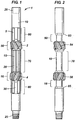
- a wellbore cleaning tool is disclosed as a spring loaded downhole tool 1 with scraping inserts is disclosed.
- Downhole tool 1 is commonly inserted as an integral one-piece or portion of a drill string within a wellbore.
- tool 1 is positioned intermediate various other tools and/or drill string portions and connected through male portion 25 and female portion 26.
- Tool 1 is most preferred for use in casing strings that are to be cleaned.
- downhole tool 1 comprises a mandrel 10, a first mounting portion 50, a second mounting portion 16, at least one first insert 2, at least one second insert 4, a first profile 5, and a second profile 30.
- mandrel 10 is of a generally similar size and/or circumference along its length with at least three cut away portions 60, 70, and 80.
- Cut away portion 60 is of a sufficient depth to allow mounting of insert 2 to a mounting slot within mounting portion 50.
- cut away portion 80 is of a sufficient depth to allow mounting of insert 4 to a mounting slot within mounting portion 16.
- Cut away portion 70 is an optional component and allows for interchangeable mounting of various tool enhancers, such as, but not limited to a magnetic portion, a tru-gauge portion, a flow area enhancement portion, and/or the like.
- first mounting portion 50 is an enlarged portion of mandrel 10 of sufficient thickness to allow machining of a mounting slot for at least one first insert 2.
- second mounting portion 16 is an enlarged portion of mandrel 10 of sufficient thickness to allow machining of a mounting slot for at least one second insert 4.
- mandrel 10 is of generally uniform circumference and the various further components of this invention are mounted to the mandrel.
- Inserts of the present invention are inserted into at least one slot 54 cut into the mounting portions from the outermost ends and not from the center.
- at least one insert 2 is inserted into a slot in mounting portion 50 from the outermost side and slid towards the center.
- at least one insert 4 is inserted into a slot in mounting portion 16 from the outermost side and slid towards the center. All embodiments of a spring loaded brush insert comprise an insert with a passageway therehtrough.
- Slots in mounting portion 50 and/or mounting portion 16 can generally be any size desired that is capable of accepting an insert.
- the slots are wedged shaped.
- the slots are L-shaped.
- the slots allow for insertion of a tongued member. Examples of slots suitable for use with various embodiments of the present invention can be found in US 4,479,538 .
- Slots in mounting portion 50 and/or mounting portion 16 can generally be cut at any orientation and/or angle from the longitudinal axis of the mandrel that allows at least one first and at least one second insert to be inserted from the outermost side. In an embodiment, all of the slots in mounting portion 50 are cut at generally the same angle. Likewise, in an embodiment, all of the slots in mounting portion 16 are cut at generally the same angle. Any number of slots can be used in each of mounting portion 50 and mounting portion 16. In an embodiment, the angle of orientation of the at least one slot is greater than 10 degrees from the longitudinal axis of the mandrel. In an alternate embodiment, the angle of orientation is greater than 20 degrees from the longitudinal axis of the mandrel.
- the angle of orientation is greater than 30 degrees from the longitudinal axis of the mandrel. In an alternate embodiment, the angle of orientation is greater than 40 degrees from the longitudinal axis of the mandrel. In an alternate embodiment, the angle of orientation is greater than 50 degrees from the longitudinal axis of the mandrel. In an alternate embodiment, the angle of orientation is greater than 60 degrees from the longitudinal axis of the mandrel. In an alternate embodiment, the angle of orientation is greater than 70 degrees from the longitudinal axis of the mandrel. In an alternate embodiment, the angle of orientation is greater than 80 degrees from the longitudinal axis of the mandrel.
- orientation/angle and number of slots is chosen to provide 360° coverage around mounting portion 50 and/or mounting portion 16.
- 360° coverage is provided by combination of mounting portion 50 and mounting portion 16.
- a brush insert comprising individually spring loaded pods is illustrated in Figure 5 and are more fully disclosed with reference to Figure 6 .
- interchangeable adaptations possible with embodiments of the present invention include interchangeable mid sections / portions located between the first insert and the second insert.
- Various embodiments of interchangeable housing portions include, but are not limited to, a blanking portion, a magnetic portion, a tru-gauging portion, combinations of the aforesaid, and/or the like.
- the embodiment in Figure 1 illustrates a magnetic housing 15 held in place on mandrel 10 by locking dog 20, in this case, a pair of locking dogs.
- retaining sleeves of the present invention are interchangeable.
- the lower retaining sleeve, retaining sleeve 30 in Figure 1 is interchangeable between a tapered mill profile, a top dress profile, a flow area enhancement profile and/or the like.
- a degree of taper is capable of selection relative to the desired drilling, milling, fishing, displacement, workover or well intervention operation and/or the like.
- the upper retaining sleeve, retaining sleeve 5 in Figure 1 is also interchangeable.
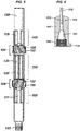
- Figure 2 is an illustration of mandrel 10 from Figure 1 without inserts, housings, or profiles. In general, at least one slot 54 is cut into of mounting portion 50 and one slot 56 is cut into mounting portion 16. Figure 2 also illustrates a hex connection 83 and a hex connection 85.
- insert 51 has a series of biased members or multiple biased members, such as springs and/or the like, counter-sunk into base 12.
- foot 9 is the biased member.
- Insert 51 is slid into slot 54 such that the biased member is positioned between the mounting portion, or mandrel, and the insert, biasing the insert outwardly from the mandrel towards the casing.
- Wear indicator 7 is capable of use to indicate when insert 51 should be replaced. In various embodiments, no foot or tongue is present.
- scraper blade insert 51 is contoured generally to the shape of the mandrel such that insert 51 slides into slot 54 and/or slot 56 from Figure 2 .
- the shape of insert 51 is arcuate.
- the edges 53, 57, 58, and 59 of scraper blade insert 51 are generally beveled to dull the edges of the insert. Beveled edges are less likely to gouge the casing as the tool is raised and lowered in the wellbore.
- the scraper insert has blades on each side such that the scraper insert is capable of scraping a surface of the wellbore as the tool is both raised and lowered in the wellbore.
- Tool 100 generally comprises at least one insert 105, with a passageway therehtrough, with at least one individually spring loaded pod 110, mandrel 120, profile 115, and profile 117.
- mandrel 120 is of a generally similar size and/or circumference along its length with at least three cut away portions 140, 150, and 160.
- Cut away portion 140 is of a sufficient depth to allow mounting of insert 105 to a mounting slot within mounting portion 102.
- cut away portion 150 is of a sufficient depth to allow mounting of insert 107 to a slot within mounting portion 104.
- Cut away portion 150 is an optional component and allows for interchangeable mounting of various tool enhancers, such as, but not limited to a magnetic portion, a tru-gauge portion, a flow area enhancement portion, and/or the like.
- first mounting portion 102 is an enlarged portion of mandrel 120 of sufficient thickness to allow machining of a mounting slot for at least one first insert 105.
- second mounting portion 104 is an enlarged portion of mandrel 120 of sufficient thickness to allow machining of a mounting slot for at least one second insert 107.
- Inserts of the present invention are inserted into at least one slot cut into the mounting portions from the outermost ends and not from the center.
- at least one insert is inserted into a slot in mounting portion from the outermost side and slid towards the center.
- at least one insert is inserted into a slot in mounting portion from the outermost side and slid towards the center.
- slots in mounting portion 102 and/or mounting portion 104 can generally be any size desired that is capable of accepting an insert.
- the slots are wedged shaped.
- the slots are L-shaped.
- the slots will provide the biasing member.
- the slots allow for insertion of a retaining tongue.
- Slots in mounting portion 102 and/or mounting portion 104 can generally be cut at any orientation and/or angle from the longitudinal axis of the mandrel that allows at least one first and at least one second insert to be inserted from the outermost side. In an embodiment, all of the slots in mounting portion 102 are cut at generally the same angle. Likewise, in an embodiment, all of the slots in mounting portion 104 are cut at generally the same angle. Any number of slots can be used in each of mounting portion 102 and mounting portion 104. In an embodiment, the angle of orientation of the at least one slot is greater than 10 degrees from the longitudinal axis of the mandrel. In an alternate embodiment, the angle of orientation is greater than 20 degrees from the longitudinal axis of the mandrel.
- the angle of orientation is greater than 30 degrees from the longitudinal axis of the mandrel. In an alternate embodiment, the angle of orientation is greater than 40 degrees from the longitudinal axis of the mandrel. In an alternate embodiment, the angle of orientation is greater than 50 degrees from the longitudinal axis of the mandrel. In an alternate embodiment, the angle of orientation is greater than 60 degrees from the longitudinal axis of the mandrel. In an alternate embodiment, the angle of orientation is greater than 70 degrees from the longitudinal axis of the mandrel. In an alternate embodiment, the angle of orientation is greater than 80 degrees from the longitudinal axis of the mandrel.
- orientation/angle and number of slots is chosen to provide 360° coverage around mounting portion 102 and/or mounting portion 104.
- 360° coverage is provided by combination of mounting portion 102 and mounting portion 104.
- interchangeable housing portions located between the first insert and the second insert.
- Various embodiments of interchangeable housing portions include, but are not limited to, a blanking portion, a magnetic portion, a flow area enhancement portion, combinations of the aforesaid, and/or the like.
- the embodiment in Figure 5 illustrates a tru-gauge clamp 125 held in place on mandrel 120 by locking dog 135, in this case, a pair of locking dogs and/or retention clamps.
- Profiles of the present invention are interchangeable.
- the lower profile, profile 117 in Figure 5 is interchangeable between a tapered mill profile, a top dress profile, a flow area enhancement profile and/or the like.
- a degree of taper is capable of selection relative to the desired drilling, milling, fishing, workover or any other cased hole intervention operation and/or the like.
- the upper profile, profile 115 in Figure 5 is also interchangeable.
- FIG. 1 is a diagrammatic representation of an embodiment of the preset invention.
- FIG. 1 is a diagrammatic representation of an embodiment of the preset invention.
- FIG. 1 is a diagrammatic representation of an embodiment of the preset invention.
- insert 110 generally comprises at least one individually spring loaded wire pod 151 comprising at least one port, a insert member 111 comprising tongue or foot 114 with at least one passageway 113 extending therethrough, a biasing member 145, and a wire filament 112.
- Pod 151 generally encases an end of wire filament 112 wherein an end of the filament 112 is crimped over a support, such as by bending over a bar.
- the wire may be notched and secured on a shelf or extending structure from the pod.
- at least one of the wire filaments is bent over the support.
- the pod is biased against/from the mandrel and insert 110 is capable of floating relative to the mandrel within the slot.
- the mandrel and the pod are therefore the biasing members.
- at least one passageway extends through insert member 111 for each pod 151.
- insert member 111 is not tongued and is retained by other means, such as being wedge shaped and/or the like.
- An embodiment of the present invention comprises a spring loaded wire brush insert positioned within the passageway of the insert and biased outwardly from the mandrel, the spring loaded wire brush insert comprising a body with at least one passageway; at least one wire filament secured at least partially within the spring loaded wire brush insert, and wherein the at least one wire filament at least partially extends through the port on the body, whereby the at least one wire filament is capable of contacting a surface of a casing.
- Further embodiments comprise a drill string and a housing portion, wherein the spring loaded wire brush insert is slidingly received within a slot on a first mounting portion on the mandrel
- the insert is slidingly received from the outermost end.
- the at least one pod and the at least one biasing member are associated with one another.
- multiple pods are associated with one biasing member.
- multiple biasing members are associated one pod.
- multiple pods are associated with multiple biasing members.
- spring loaded wire brush inserts of the present invention such as in the case of repair, allowing for individual pod and/or brush insert replacement, allowing for varied biased members across the insert, allowing for greater casing contact in deviated section of the casing, allowing of ease of change between scraper inserts and brush inserts, allowing for float of the pod inserts and/or the wire brush inserts regardless of casing ovality/inner casing diameter variances thereby reducing and/or eliminating the occurrences of tram lines where fixed radiuses don't match up; allowing for an improved high contact system; allowing for ease of removal of brush inserts, improving safety of personnel during removal and/or changing operations, and/or the like.
- No embodiments of the present invention comprise a first spring loaded brush insert and a second spring loaded brush insert operatively associated with the tool, wherein the spring loaded brush insert comprises a mandrel having a slot; an insert received within the slot, wherein the insert has a first section containing an opening for placing a wire filament therethrough; a spring, positioned between the mandrel and the brush insert for biasing the brush insert against the inner diameter of the casing string.
- All embodiments of brush inserts the present invention comprise at least one individually spring loaded pod or spring loaded insert for enhanced casing cleaning.
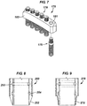
- Figure 7 is an illustration of a pod-loaded insert 175 comprising at least one individually spring loaded pod 176, spring loaded brush insert 178, tongued insert/biasing member 183, and access passageway 181.
- the fixed blade will be secured to the mandrel in combination with the slot profile and blade profile.
- the spring loaded pods will be retained within correlating blade profiles and act independently to the blade.
- the spring mechanism in combination with the wire pod will be operable and secured within the bored sections of the blade.
- the wire filaments will be secured to the pod housing by means of a positive locking system.
- the wire strands, composing of the wire filament will be folded, twisted, and/or crimped to reduce wire fatigue and improve casing wall contact and/or cleaning.
- the wire extension, beyond the blade outer diameter will remain short, rigid, and/or abundant thus providing for an enhanced casing inner diameter cleaning.
- Figure 8 is an illustration of an embodiment of a profile 250 with a gradual tapered mill.
- Taper 252 can be varied as desired.
- Profile 250 is secured to a mandrel by any means common in the art.
- a retaining key locking feature is used to secure the retaining sleeve.
- a locking mechanism will be inserted and isolated within the mounting region.
- the retaining key locking feature is locking dogs, retaining keys 254, ball(s) 253, locking wire, screw, bolts, threaded connection, fastner, interference fit, and/or the like.
- the retaining device(s) are capable of providing the tensile and compressional resistance necessary to secure the various inserts in the slots during drilling operations. Accordingly, the profiles of the present invention secure the various inserts in the slots.
- an additional locking mechanism or profile, will be positioned to secure the retaining sleeve torsionally thus not allowing the sleeve to rotate opposite the mandrel.
- the retaining sleeves will be positioned over the undercuts in the mandrel.
- the retaining sleeve is held in place by alternate means, such as, but not limited to a screw thread, at least one bolt, a pin, a hex fitting, a bearing, a gear, a spline, and/or the like.
- any method common in the art can be used to secure the sleeve to the mandrel.
- the undercuts will accept two stainless (or similar material) split halves with the locking profile machined to coincide with the retainer sleeve locking profile. Once aligned, the locking mechanism(s) are capable of being inserted, thus locking the two components together. These split halves are designed to be interchangeable and used to preserve the mandrel integrity and life.
- Figure 9 is an illustration of a top dress tapered mill profile 270 with a taper 272.
- Figure 10 is an illustration of a sharp tapered mill profile 280.
- the taper 282 is less than that of Figure 8 , thereby illustrating that a taper of a profile on a retaining sleeve of the present invention can be modified.
- FIG 11 is an illustration of a magnetic housing portion 200.
- housing portion 200 is secured in cut away portion 70 by locking dog(s) 210.
- housing portion 200 has ports for accepting the locking dogs. The locking dogs will prevent and/or resist rotation of the housing portion.
- magnetic bars 220 are slid into carriers/slots on portion 200.
- a housing portion of the present invention is generally a sheet of material or materials that is wrapped around the mandrel.
- the sheet can be secured by any means common in the art, such as, but not limited to bolting, welding, screwing, stabbing, and/or the like.
- the embodiment in Figure 11 comprises magnetic portions.
- the magnetic portion can be added by any means.
- the magnetic portion can be used to remove metallic debris from the wellbore, thereby reducing the amount of metallic material in the drilling, completion, and/or wellbore fluid and increasing and/or improving the service life and condition of those fluids, tools, subsequent wellbore activities and/or the like.
- Figure 12 is an illustration of a tru-gauge housing portion 300.
- the tru-gauge is a positive casing drill and/or gauging device used to simulate other downhole equipment and/or jewelry to be utilized or deployed in the casing and/or the wellbore on subsequent well intervention runs.
- Figure 13 is an illustration of a blanking housing portion 400.
- the illustration of blanking housing portion 400 provides an alternate/additional means of securing the sheet, such that a bar or key 440 can be used to connect the opposing ends of the sheet of the housing portion.
- the blanking housing provides protection to the mandrel should no other mid section option be utilized.
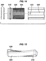
- Figure 14 discloses an alternate embodiment of a profile and insert locking mechanism.
- a cut-away portion 140 and/or cut-away portion 160 from Figure 5 has a geometrical shaped surface and profile retainer 505 has a complimentary geometrically shaped interior surface such that retainer 505 locks does not rotate when when inserted into place.
- Ribs or gears 520 cooperate with an interior surface of profile 530 to resist rotation. Further locking of profile 530 can be achieved with the use of a bearing system 510.
- gaskets 500 are used to prevent or inhibit drilling fluid or other fluid from passing between profile 530 and retainer 505.
- FIG 15 is an illustration of a spring loaded insert 600 capable of use in various embodiments of the present invention.
- Passageway 610 is elongated along a base of insert 600. Cut-out 620 extend through insert 600 as is better seen with reference to Figure 16 .
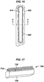
- Figure 16 illustrates passageway 610 is tapered such that when a wire brush insert as disclosed in Figure 17 is inserted into passageway 610 the taper does not allow the wire brush insert to pass through passageway 610.
- the taper can be gradual, arcuate, shelf like, or generally any other taper common in the art and capable of resisteing the wire brush insert from passing through spring loaded insert 610.
- Cut-out 620 is generally any shape capable of allowing a biasing member to bias the mandrel and a wire brush insert.
- a circular wound spring is used and cut-out 620 is generally circular in shape extending at least a portion of the distance through insert 600, but not through insert 600.
- Figure 17 discloses a wire brush insert 700 capable of use with embodiments of the present invention comprising a base 730 and at least one wire filament 710.
- any method of securing wire filaments 710 within insert 700 is capable of use in various embodiments.
- wire filament 710 is secured in insert 700 by crimping of insert 700 such that insert 700 is tapered inwardly from base 730 in at least portion 720.
- any manner of securing wire filament 710 is capable of use.
- Also disclosed are methods of cleaning a wellbore comprising the steps of lowering or raising a drill string comprising at least one spring loaded wellbore cleaning tool into a wellbore to at least one section of casing that needs cleaning, the tool comprising at least one spring loaded brush insert as herein disclosed; and, cleaning the at least one section by rotating the drill string, whereby each of the at least one spring loaded pods is biased outwardly from the mandrel towards the at least one section of casing wherein the at least one section of casing is brushed.
- Further embodiments comprise a step of scraping the at least one section of casing.
- Further embodiments comprise a step of magnetically attracting metallic debris within the at least one section of casing.
- Further embodiments comprise the step of centering the tool within the wellbore.
- Further embodiments comprise the step of circulating a drilling fluid through the inner diameter of the work string.
- Methods and apparatuses of the present invention arc particularly useful in drill strings with deviated sections.
- a tool of the present invention will work in any wellbore, deviated or not.
- embodiments of the present invention are particularly meant to cover a wellbore cleaning tool comprising a mandrel connected to a drill string, said mandrel comprising; at least a first insert with a passageway therethrough; at least a second insert; and, a housing portion, wherein at least said first insert comprises a spring loaded brush insert with a passageway therethrough, wherein said spring loaded brush insert is biased outwardly with a biasing member from said mandrel, and further wherein said first insert and said second insert are slidingly received within a slot on a first mounting portion on said mandrel and a slot on a second mounting portion on said mandrel, from the outermost respective ends, and wherein said first insert is secured by a first retaining sleeve and said second insert is secured by a second retaining sleeve; a spring loaded wellbore cleaning tool comprising a mandrel connected to a drill string; at least a first insert with a passageway therethrough; at least a second insert
Landscapes
- Geology (AREA)
- Life Sciences & Earth Sciences (AREA)
- Engineering & Computer Science (AREA)
- Mining & Mineral Resources (AREA)
- Geochemistry & Mineralogy (AREA)
- Fluid Mechanics (AREA)
- Environmental & Geological Engineering (AREA)
- General Life Sciences & Earth Sciences (AREA)
- Physics & Mathematics (AREA)
- Brushes (AREA)
- Cleaning In General (AREA)
- Polishing Bodies And Polishing Tools (AREA)
- Grinding-Machine Dressing And Accessory Apparatuses (AREA)
- Lubricants (AREA)
- Mechanical Treatment Of Semiconductor (AREA)
- Cleaning Implements For Floors, Carpets, Furniture, Walls, And The Like (AREA)
- Drilling Tools (AREA)
Priority Applications (3)
| Application Number | Priority Date | Filing Date | Title |
|---|---|---|---|
| EP18170276.2A EP3372779B1 (en) | 2006-12-12 | 2007-12-12 | Mproved downhole scraping and/or brushing tool |
| DK18170276T DK3372779T3 (da) | 2006-12-12 | 2007-12-12 | Forbedret borehulsskrabe- og/eller børsteredskab |
| CY20191101236T CY1122318T1 (el) | 2006-12-12 | 2019-11-26 | Βελτιωμενο εργαλειο πυθμενα για την αποξεση και/ή το βουρτσισμα φρεατιου |
Applications Claiming Priority (2)
| Application Number | Priority Date | Filing Date | Title |
|---|---|---|---|
| US86971206P | 2006-12-12 | 2006-12-12 | |
| PCT/US2007/087287 WO2008073986A2 (en) | 2006-12-12 | 2007-12-12 | Improved downhole scraping and/or brushing tool and related methods |
Related Child Applications (1)
| Application Number | Title | Priority Date | Filing Date |
|---|---|---|---|
| EP18170276.2A Division EP3372779B1 (en) | 2006-12-12 | 2007-12-12 | Mproved downhole scraping and/or brushing tool |
Publications (3)
| Publication Number | Publication Date |
|---|---|
| EP2097613A2 EP2097613A2 (en) | 2009-09-09 |
| EP2097613A4 EP2097613A4 (en) | 2014-11-19 |
| EP2097613B1 true EP2097613B1 (en) | 2018-05-02 |
Family
ID=39512469
Family Applications (2)
| Application Number | Title | Priority Date | Filing Date |
|---|---|---|---|
| EP07865592.5A Active EP2097613B1 (en) | 2006-12-12 | 2007-12-12 | Improved downhole scraping and/or brushing tool and related methods |
| EP18170276.2A Active EP3372779B1 (en) | 2006-12-12 | 2007-12-12 | Mproved downhole scraping and/or brushing tool |
Family Applications After (1)
| Application Number | Title | Priority Date | Filing Date |
|---|---|---|---|
| EP18170276.2A Active EP3372779B1 (en) | 2006-12-12 | 2007-12-12 | Mproved downhole scraping and/or brushing tool |
Country Status (14)
| Country | Link |
|---|---|
| US (2) | US20100186962A1 (pt) |
| EP (2) | EP2097613B1 (pt) |
| AP (1) | AP2594A (pt) |
| AU (1) | AU2007333080B2 (pt) |
| BR (1) | BRPI0719982B1 (pt) |
| CA (2) | CA2887485C (pt) |
| CO (1) | CO6210709A2 (pt) |
| CY (2) | CY1120456T1 (pt) |
| DK (2) | DK2097613T3 (pt) |
| EA (1) | EA015116B1 (pt) |
| MX (1) | MX2009006399A (pt) |
| MY (1) | MY151874A (pt) |
| NO (2) | NO344046B1 (pt) |
| WO (1) | WO2008073986A2 (pt) |
Families Citing this family (29)
| Publication number | Priority date | Publication date | Assignee | Title |
|---|---|---|---|---|
| MY159006A (en) * | 2007-07-06 | 2016-11-30 | Halliburton Energy Services Inc | Multi-purpose well servicing apparatus |
| US20090272524A1 (en) * | 2008-05-02 | 2009-11-05 | Voth Rickey C | Method and apparatus for cleaning internal surfaces of downhole casing strings and other tubular goods |
| US9228400B2 (en) * | 2010-02-15 | 2016-01-05 | Antelope Oil Tool & Mfg. Co. | Device and method for affecting the flow of fluid in a wellbore |
| US8511375B2 (en) * | 2010-05-03 | 2013-08-20 | Baker Hughes Incorporated | Wellbore cleaning devices |
| USD632309S1 (en) * | 2010-05-03 | 2011-02-08 | Bilco Tools, Inc. | Downhole magnet jet tool |
| USD632310S1 (en) * | 2010-05-13 | 2011-02-08 | Bilco Tools, Inc. | Downhole brush tool |
| US20120138369A1 (en) * | 2010-12-06 | 2012-06-07 | Smith International, Inc. | Methods to manufacture downhole tools with finished features as an integral cage |
| GB201115459D0 (en) * | 2011-09-07 | 2011-10-26 | Oilsco Technologies Ltd | Apparatus and method |
| US9435176B2 (en) | 2012-10-26 | 2016-09-06 | Weatherford Technology Holdings, Llc | Deburring mill tool for wellbore cleaning |
| CN105518248B (zh) | 2013-07-05 | 2019-09-24 | 布鲁斯·A.·通盖特 | 用于培养井下表面的设备和方法 |
| CA2869299C (en) | 2013-11-05 | 2018-10-09 | Weatherford/Lamb, Inc. | Magnetic retrieval apparatus |
| CA2940729C (en) | 2014-03-11 | 2022-03-15 | Qinterra Technologies As | Tool for internal cleaning of a tubing or casing |
| EP3147056A1 (de) * | 2015-09-23 | 2017-03-29 | HILTI Aktiengesellschaft | Werkzeug zum aufrauen einer bohrlochoberfläche |
| US10557330B2 (en) * | 2017-04-24 | 2020-02-11 | Saudi Arabian Oil Company | Interchangeable wellbore cleaning modules |
| WO2020068103A1 (en) * | 2018-09-28 | 2020-04-02 | Halliburton Energy Services, Inc. | Drillable casing scraper |
| NO20210345A1 (en) * | 2018-10-30 | 2021-03-18 | Halliburton Energy Services Inc | Rotating/non-rotating casing cleaning tool |
| CN111379540B (zh) * | 2018-12-29 | 2021-11-30 | 中国石油天然气股份有限公司 | 油水井机械通管工具 |
| CN109915075B (zh) * | 2019-04-19 | 2021-04-13 | 新疆华油油气工程有限公司 | 具有铣刮通功能的井下工具 |
| IL289302B2 (en) | 2019-07-02 | 2025-04-01 | Halliburton Energy Services Inc | Fluid-powered rotary cleaning tool |
| CN110529074B (zh) * | 2019-10-20 | 2024-06-11 | 上海达坦能源科技股份有限公司 | 一种钻头同步旋转刮管器 |
| US20220410057A1 (en) * | 2019-11-04 | 2022-12-29 | Emerging Acquisitions, Llc | Macro anti-fouling screen functioning in multi-directional flow |
| US20230040253A1 (en) * | 2019-12-27 | 2023-02-09 | Petróleo Brasileiro S.A. - Petrobras | System for eliminating and removing hydrates and other blockages in undersea lines |
| CN111101898B (zh) * | 2020-01-07 | 2022-07-08 | 中石化石油工程技术服务有限公司 | 一种超深高含硫气井试井钢丝作业刮硫装置 |
| RU209364U1 (ru) * | 2021-04-27 | 2022-03-15 | Салават Анатольевич Кузяев | Скважинный скрепер |
| CN114526035A (zh) * | 2021-12-31 | 2022-05-24 | 中国石油天然气集团有限公司 | 一种套管清洗工具及其相关机构、方法和应用 |
| US12228015B2 (en) * | 2022-10-27 | 2025-02-18 | Saudi Arabian Oil Company | Adjustable brush plug device |
| US20240191600A1 (en) * | 2022-12-13 | 2024-06-13 | Saudi Arabian Oil Company | Cleaning a valve profile in a wellhead |
| WO2024248810A1 (en) * | 2023-05-31 | 2024-12-05 | Halliburton Energy Services, Inc. | Completions-based well cleanout using magnetic cleanout tool |
| US20250290382A1 (en) * | 2024-03-12 | 2025-09-18 | Saudi Arabian Oil Company | Conditioning a tubing head back pressure valve receptacle |
Family Cites Families (47)
| Publication number | Priority date | Publication date | Assignee | Title |
|---|---|---|---|---|
| US2667930A (en) * | 1948-04-06 | 1954-02-02 | Baker Oil Tools Inc | Casing scraper |
| US2667931A (en) * | 1949-08-01 | 1954-02-02 | Baker Oil Tools Inc | Casing scraper |
| US2695673A (en) * | 1952-07-21 | 1954-11-30 | William E Coyle | Well casing scraping tool |
| US2838121A (en) * | 1953-10-14 | 1958-06-10 | William E Coyle | Well casing scraping and polishing tool |
| US2811210A (en) * | 1954-08-19 | 1957-10-29 | Burton A Guillot | Casing scraper |
| US3176772A (en) * | 1963-03-29 | 1965-04-06 | Macgregor Robert Roy | Device for removing detrital material from a liner, tubing and casing |
| GB1235656A (en) * | 1969-01-22 | 1971-06-16 | William Mayall | Improvements in or relating to earth drilling apparatus |
| US4479538A (en) * | 1981-06-22 | 1984-10-30 | Bilco Tools, Inc. | Casing scraper and method for making the same |
| US4593775A (en) * | 1985-04-18 | 1986-06-10 | Smith International, Inc. | Two-piece pressure relief valve |
| US4798246A (en) * | 1987-04-22 | 1989-01-17 | Best David M | Pipe scraper |
| US5178757A (en) * | 1990-06-29 | 1993-01-12 | Mag-Well, Inc. | Magnetic, fluid-conditioning tools |
| US5419397A (en) * | 1993-06-16 | 1995-05-30 | Well-Flow Technologies, Inc. | Well cleaning tool with scratching elements |
| US5452760A (en) * | 1994-09-19 | 1995-09-26 | Enterra Patco Oilfield Products Limited | Well pump tubing scrapers |
| AUPN469395A0 (en) * | 1995-08-08 | 1995-08-31 | Gearhart United Pty Ltd | Borehole drill bit stabiliser |
| GB9517829D0 (en) * | 1995-09-01 | 1995-11-01 | Oiltools Int Bv | Tool for cleaning or conditioning tubular structures such as well casings |
| US5829521A (en) * | 1997-02-21 | 1998-11-03 | Brown, Jr.; Billy L. | Down hole cleaning device and method |
| GB9809408D0 (en) * | 1998-05-02 | 1998-07-01 | Drilltech Serv North Sea Ltd | Downhole apparatus |
| GB9803824D0 (en) * | 1998-02-24 | 1998-04-22 | Specialised Petroleum Serv Ltd | Compact well clean-up tool with multi-functional cleaning apparatus |
| US6152220A (en) * | 1998-06-07 | 2000-11-28 | Specialised Petroleum Services Limited | Down-hole tool with centralising component |
| GB9813422D0 (en) * | 1998-06-23 | 1998-08-19 | Specialised Petroleum Serv Ltd | Down-hole tool with detachable cleaning pads |
| US6464010B1 (en) * | 1998-08-13 | 2002-10-15 | Global Completion Services, Inc. | Apparatus and method for cleaning a tubular member with a brush |
| GB9902595D0 (en) * | 1999-02-08 | 1999-03-24 | Specialised Petroleum Serv Ltd | Apparatus with retractable cleaning members |
| GB9912666D0 (en) * | 1999-05-29 | 1999-07-28 | Specialised Petroleum Serv Ltd | Magnetic well cleaning apparatus |
| US6371207B1 (en) * | 1999-06-10 | 2002-04-16 | M-I L.L.C. | Method and apparatus for displacing drilling fluids with completion and workover fluids, and for cleaning tubular members |
| GB0002995D0 (en) * | 2000-02-10 | 2000-03-29 | Specialised Petroleum Serv Ltd | Downhole cleaning tool with shear clutch |
| AU2001240792A1 (en) * | 2000-03-10 | 2001-09-17 | Nortech Systems Limited | Clean out tool |
| RU2271439C2 (ru) * | 2000-03-31 | 2006-03-10 | М-Ай Л.Л.С. | Способ и устройство для очистки обсадной колонны ствола скважины |
| CA2413539C (en) * | 2000-06-21 | 2009-01-13 | Deep Casing Tools Limited | Centraliser |
| GB0026460D0 (en) * | 2000-10-27 | 2000-12-13 | Sps Afos Internat Branch Ltd | Combined milling and scraping tool |
| GB0207851D0 (en) * | 2002-04-05 | 2002-05-15 | Sps Afos Group Ltd | Stabiliser jetting and circulating tool |
| GB0306821D0 (en) * | 2003-03-25 | 2003-04-30 | Specialised Petroleum Serv Ltd | Dual function cleaning tool |
| DE10347851A1 (de) * | 2003-10-10 | 2005-06-09 | Eisenmann Maschinenbau Gmbh & Co. Kg | Vorrichtung zur berührungslosen Übertragung elektrischer Energie |
| CA2499532C (en) * | 2004-03-11 | 2012-11-20 | Smith International, Inc. | Casing scraper |
| CA2499525C (en) * | 2004-03-11 | 2012-11-27 | Smith International, Inc. | Casing brush assembly |
| US7219724B2 (en) * | 2004-07-15 | 2007-05-22 | Bilco Tools, Inc. | Downhole magnetic retrieval tool |
| GB0505166D0 (en) * | 2005-03-14 | 2005-04-20 | Stewart Arthur | Multi-function downhole tool |
| US20060201670A1 (en) * | 2005-03-14 | 2006-09-14 | Stable Services Limited | Downhole apparatus |
| US20070261855A1 (en) * | 2006-05-12 | 2007-11-15 | Travis Brunet | Wellbore cleaning tool system and method of use |
| GB0612091D0 (en) * | 2006-06-19 | 2006-07-26 | Hamdeen Inc Ltd | Device for downhole tools |
| GB0704382D0 (en) * | 2007-03-07 | 2007-04-11 | Rotary Drilling Supplies Europ | Apparatus |
| MY159006A (en) * | 2007-07-06 | 2016-11-30 | Halliburton Energy Services Inc | Multi-purpose well servicing apparatus |
| GB2454450B (en) * | 2007-09-04 | 2012-01-11 | Weatherford Switzerland Trading And Dev Gmbh | Downhole cleaning tool |
| AR062973A1 (es) * | 2007-09-25 | 2008-12-17 | Carro Gustavo Ignacio | Paquer recuperable para operaciones en pozos entubados |
| US8356662B2 (en) * | 2008-04-14 | 2013-01-22 | Well Grounded Energy, LLC | Devices, systems and methods relating to down hole operations |
| US20090272524A1 (en) * | 2008-05-02 | 2009-11-05 | Voth Rickey C | Method and apparatus for cleaning internal surfaces of downhole casing strings and other tubular goods |
| CN101725564B (zh) * | 2008-10-16 | 2013-06-05 | 富准精密工业(深圳)有限公司 | 离心风扇及使用该离心风扇的散热装置 |
| US7712520B1 (en) * | 2008-10-21 | 2010-05-11 | Weiler Corporation | Brush for a well bore casing |
-
2007
- 2007-12-12 EP EP07865592.5A patent/EP2097613B1/en active Active
- 2007-12-12 MX MX2009006399A patent/MX2009006399A/es active IP Right Grant
- 2007-12-12 DK DK07865592.5T patent/DK2097613T3/en active
- 2007-12-12 WO PCT/US2007/087287 patent/WO2008073986A2/en not_active Ceased
- 2007-12-12 US US12/519,124 patent/US20100186962A1/en not_active Abandoned
- 2007-12-12 CA CA2887485A patent/CA2887485C/en active Active
- 2007-12-12 MY MYPI20092811 patent/MY151874A/en unknown
- 2007-12-12 EA EA200970577A patent/EA015116B1/ru active IP Right Revival
- 2007-12-12 AP AP2009004911A patent/AP2594A/xx active
- 2007-12-12 EP EP18170276.2A patent/EP3372779B1/en active Active
- 2007-12-12 DK DK18170276T patent/DK3372779T3/da active
- 2007-12-12 BR BRPI0719982A patent/BRPI0719982B1/pt active IP Right Grant
- 2007-12-12 CA CA2672627A patent/CA2672627C/en active Active
- 2007-12-12 AU AU2007333080A patent/AU2007333080B2/en active Active
-
2009
- 2009-06-24 CO CO09065387A patent/CO6210709A2/es active IP Right Grant
- 2009-07-08 NO NO20092592A patent/NO344046B1/no unknown
-
2012
- 2012-04-10 US US13/443,858 patent/US8376043B2/en active Active
-
2018
- 2018-07-17 CY CY20181100744T patent/CY1120456T1/el unknown
-
2019
- 2019-05-09 NO NO20190584A patent/NO344497B1/no unknown
- 2019-11-26 CY CY20191101236T patent/CY1122318T1/el unknown
Non-Patent Citations (1)
| Title |
|---|
| None * |
Also Published As
| Publication number | Publication date |
|---|---|
| US20120241145A1 (en) | 2012-09-27 |
| NO344497B1 (no) | 2020-01-20 |
| EP3372779A1 (en) | 2018-09-12 |
| CA2887485A1 (en) | 2008-06-19 |
| WO2008073986A3 (en) | 2008-10-09 |
| CY1122318T1 (el) | 2021-01-27 |
| EA200970577A1 (ru) | 2010-02-26 |
| NO20190584A1 (no) | 2009-09-04 |
| CA2672627C (en) | 2016-05-10 |
| EP2097613A4 (en) | 2014-11-19 |
| CA2887485C (en) | 2016-12-20 |
| BRPI0719982A2 (pt) | 2012-02-28 |
| AU2007333080B2 (en) | 2014-04-03 |
| AP2594A (en) | 2013-02-08 |
| DK2097613T3 (en) | 2018-06-18 |
| WO2008073986A2 (en) | 2008-06-19 |
| NO20092592L (no) | 2009-09-04 |
| MX2009006399A (es) | 2009-11-26 |
| EP3372779B1 (en) | 2019-09-04 |
| MY151874A (en) | 2014-07-14 |
| EA015116B1 (ru) | 2011-06-30 |
| AU2007333080A2 (en) | 2009-12-10 |
| US20100186962A1 (en) | 2010-07-29 |
| CA2672627A1 (en) | 2008-06-19 |
| DK3372779T3 (da) | 2019-11-11 |
| BRPI0719982B1 (pt) | 2018-07-17 |
| NO344046B1 (no) | 2019-08-26 |
| US8376043B2 (en) | 2013-02-19 |
| CO6210709A2 (es) | 2010-10-20 |
| AP2009004911A0 (en) | 2009-08-31 |
| CY1120456T1 (el) | 2019-07-10 |
| AU2007333080A1 (en) | 2008-06-19 |
| EP2097613A2 (en) | 2009-09-09 |
Similar Documents
| Publication | Publication Date | Title |
|---|---|---|
| EP2097613B1 (en) | Improved downhole scraping and/or brushing tool and related methods | |
| US5819353A (en) | Tool for cleaning or conditioning tubular structures such as well casings | |
| US4512425A (en) | Up-drill sub for use in rotary drilling | |
| EP1561002B1 (en) | An improved rotary roller reamer | |
| US4479538A (en) | Casing scraper and method for making the same | |
| GB2312906A (en) | High pressure casing patch | |
| CA2307627C (en) | Mill for use in a wellbore and method of milling | |
| US20180252044A1 (en) | Earth-boring tools including bearing element assemblies, and related methods | |
| US9702196B2 (en) | Coring tool including core bit and drilling plug with alignment and torque transmission apparatus and related methods | |
| CN111032992A (zh) | 包括可旋转切削元件的切削元件组件和井下工具及相关方法 | |
| EP0585106A2 (en) | Threaded retention ring for roller bit and method for manufacturing such a bit | |
| EP1254299A2 (en) | Drill pipe torque-reduction and protection apparatus | |
| AU2013205035B2 (en) | Improved downhole scraping and/or brushing tool | |
| US20230287743A1 (en) | Improved drill bit | |
| EP0234697A2 (en) | Cutter | |
| US20070163778A1 (en) | Casing Centralizer Coupling | |
| AU2021294605B2 (en) | Improved drill bit | |
| CA2533563A1 (en) | Casing centralizer coupling | |
| AU2004236273B2 (en) | Stabilising band for a roller assembly | |
| EP1627128A1 (en) | Stabilising band for a roller assembly |
Legal Events
| Date | Code | Title | Description |
|---|---|---|---|
| PUAI | Public reference made under article 153(3) epc to a published international application that has entered the european phase |
Free format text: ORIGINAL CODE: 0009012 |
|
| 17P | Request for examination filed |
Effective date: 20090629 |
|
| AK | Designated contracting states |
Kind code of ref document: A2 Designated state(s): AT BE BG CH CY CZ DE DK EE ES FI FR GB GR HU IE IS IT LI LT LU LV MC MT NL PL PT RO SE SI SK TR |
|
| DAX | Request for extension of the european patent (deleted) | ||
| RAP1 | Party data changed (applicant data changed or rights of an application transferred) |
Owner name: HALLIBURTON ENERGY SERVICES, INC. |
|
| A4 | Supplementary search report drawn up and despatched |
Effective date: 20141017 |
|
| RIC1 | Information provided on ipc code assigned before grant |
Ipc: E21B 37/02 20060101ALI20141013BHEP Ipc: E21B 37/08 20060101ALI20141013BHEP Ipc: E21B 37/00 20060101AFI20141013BHEP |
|
| 17Q | First examination report despatched |
Effective date: 20160802 |
|
| STAA | Information on the status of an ep patent application or granted ep patent |
Free format text: STATUS: EXAMINATION IS IN PROGRESS |
|
| GRAP | Despatch of communication of intention to grant a patent |
Free format text: ORIGINAL CODE: EPIDOSNIGR1 |
|
| STAA | Information on the status of an ep patent application or granted ep patent |
Free format text: STATUS: GRANT OF PATENT IS INTENDED |
|
| INTG | Intention to grant announced |
Effective date: 20180102 |
|
| GRAS | Grant fee paid |
Free format text: ORIGINAL CODE: EPIDOSNIGR3 |
|
| GRAA | (expected) grant |
Free format text: ORIGINAL CODE: 0009210 |
|
| STAA | Information on the status of an ep patent application or granted ep patent |
Free format text: STATUS: THE PATENT HAS BEEN GRANTED |
|
| AK | Designated contracting states |
Kind code of ref document: B1 Designated state(s): AT BE BG CH CY CZ DE DK EE ES FI FR GB GR HU IE IS IT LI LT LU LV MC MT NL PL PT RO SE SI SK TR |
|
| REG | Reference to a national code |
Ref country code: GB Ref legal event code: FG4D |
|
| REG | Reference to a national code |
Ref country code: CH Ref legal event code: EP Ref country code: AT Ref legal event code: REF Ref document number: 995456 Country of ref document: AT Kind code of ref document: T Effective date: 20180515 |
|
| REG | Reference to a national code |
Ref country code: DE Ref legal event code: R096 Ref document number: 602007054768 Country of ref document: DE Ref country code: IE Ref legal event code: FG4D |
|
| REG | Reference to a national code |
Ref country code: DE Ref legal event code: R096 Ref document number: 602007054768 Country of ref document: DE |
|
| REG | Reference to a national code |
Ref country code: RO Ref legal event code: EPE |
|
| REG | Reference to a national code |
Ref country code: DK Ref legal event code: T3 Effective date: 20180612 |
|
| REG | Reference to a national code |
Ref country code: LT Ref legal event code: MG4D |
|
| PG25 | Lapsed in a contracting state [announced via postgrant information from national office to epo] |
Ref country code: SE Free format text: LAPSE BECAUSE OF FAILURE TO SUBMIT A TRANSLATION OF THE DESCRIPTION OR TO PAY THE FEE WITHIN THE PRESCRIBED TIME-LIMIT Effective date: 20180502 Ref country code: ES Free format text: LAPSE BECAUSE OF FAILURE TO SUBMIT A TRANSLATION OF THE DESCRIPTION OR TO PAY THE FEE WITHIN THE PRESCRIBED TIME-LIMIT Effective date: 20180502 Ref country code: BG Free format text: LAPSE BECAUSE OF FAILURE TO SUBMIT A TRANSLATION OF THE DESCRIPTION OR TO PAY THE FEE WITHIN THE PRESCRIBED TIME-LIMIT Effective date: 20180802 Ref country code: FI Free format text: LAPSE BECAUSE OF FAILURE TO SUBMIT A TRANSLATION OF THE DESCRIPTION OR TO PAY THE FEE WITHIN THE PRESCRIBED TIME-LIMIT Effective date: 20180502 Ref country code: LT Free format text: LAPSE BECAUSE OF FAILURE TO SUBMIT A TRANSLATION OF THE DESCRIPTION OR TO PAY THE FEE WITHIN THE PRESCRIBED TIME-LIMIT Effective date: 20180502 |
|
| PG25 | Lapsed in a contracting state [announced via postgrant information from national office to epo] |
Ref country code: GR Free format text: LAPSE BECAUSE OF FAILURE TO SUBMIT A TRANSLATION OF THE DESCRIPTION OR TO PAY THE FEE WITHIN THE PRESCRIBED TIME-LIMIT Effective date: 20180803 Ref country code: LV Free format text: LAPSE BECAUSE OF FAILURE TO SUBMIT A TRANSLATION OF THE DESCRIPTION OR TO PAY THE FEE WITHIN THE PRESCRIBED TIME-LIMIT Effective date: 20180502 |
|
| REG | Reference to a national code |
Ref country code: AT Ref legal event code: MK05 Ref document number: 995456 Country of ref document: AT Kind code of ref document: T Effective date: 20180502 |
|
| PG25 | Lapsed in a contracting state [announced via postgrant information from national office to epo] |
Ref country code: PT Free format text: LAPSE BECAUSE OF FAILURE TO SUBMIT A TRANSLATION OF THE DESCRIPTION OR TO PAY THE FEE WITHIN THE PRESCRIBED TIME-LIMIT Effective date: 20180903 |
|
| PG25 | Lapsed in a contracting state [announced via postgrant information from national office to epo] |
Ref country code: CZ Free format text: LAPSE BECAUSE OF FAILURE TO SUBMIT A TRANSLATION OF THE DESCRIPTION OR TO PAY THE FEE WITHIN THE PRESCRIBED TIME-LIMIT Effective date: 20180502 Ref country code: EE Free format text: LAPSE BECAUSE OF FAILURE TO SUBMIT A TRANSLATION OF THE DESCRIPTION OR TO PAY THE FEE WITHIN THE PRESCRIBED TIME-LIMIT Effective date: 20180502 Ref country code: PL Free format text: LAPSE BECAUSE OF FAILURE TO SUBMIT A TRANSLATION OF THE DESCRIPTION OR TO PAY THE FEE WITHIN THE PRESCRIBED TIME-LIMIT Effective date: 20180502 Ref country code: SK Free format text: LAPSE BECAUSE OF FAILURE TO SUBMIT A TRANSLATION OF THE DESCRIPTION OR TO PAY THE FEE WITHIN THE PRESCRIBED TIME-LIMIT Effective date: 20180502 Ref country code: AT Free format text: LAPSE BECAUSE OF FAILURE TO SUBMIT A TRANSLATION OF THE DESCRIPTION OR TO PAY THE FEE WITHIN THE PRESCRIBED TIME-LIMIT Effective date: 20180502 |
|
| REG | Reference to a national code |
Ref country code: DE Ref legal event code: R097 Ref document number: 602007054768 Country of ref document: DE |
|
| PG25 | Lapsed in a contracting state [announced via postgrant information from national office to epo] |
Ref country code: IT Free format text: LAPSE BECAUSE OF FAILURE TO SUBMIT A TRANSLATION OF THE DESCRIPTION OR TO PAY THE FEE WITHIN THE PRESCRIBED TIME-LIMIT Effective date: 20180502 |
|
| PLBE | No opposition filed within time limit |
Free format text: ORIGINAL CODE: 0009261 |
|
| STAA | Information on the status of an ep patent application or granted ep patent |
Free format text: STATUS: NO OPPOSITION FILED WITHIN TIME LIMIT |
|
| 26N | No opposition filed |
Effective date: 20190205 |
|
| PG25 | Lapsed in a contracting state [announced via postgrant information from national office to epo] |
Ref country code: SI Free format text: LAPSE BECAUSE OF FAILURE TO SUBMIT A TRANSLATION OF THE DESCRIPTION OR TO PAY THE FEE WITHIN THE PRESCRIBED TIME-LIMIT Effective date: 20180502 |
|
| REG | Reference to a national code |
Ref country code: DE Ref legal event code: R119 Ref document number: 602007054768 Country of ref document: DE |
|
| REG | Reference to a national code |
Ref country code: CH Ref legal event code: PL |
|
| PG25 | Lapsed in a contracting state [announced via postgrant information from national office to epo] |
Ref country code: LU Free format text: LAPSE BECAUSE OF NON-PAYMENT OF DUE FEES Effective date: 20181212 Ref country code: MC Free format text: LAPSE BECAUSE OF FAILURE TO SUBMIT A TRANSLATION OF THE DESCRIPTION OR TO PAY THE FEE WITHIN THE PRESCRIBED TIME-LIMIT Effective date: 20180502 |
|
| REG | Reference to a national code |
Ref country code: IE Ref legal event code: MM4A |
|
| REG | Reference to a national code |
Ref country code: BE Ref legal event code: MM Effective date: 20181231 |
|
| PG25 | Lapsed in a contracting state [announced via postgrant information from national office to epo] |
Ref country code: DE Free format text: LAPSE BECAUSE OF NON-PAYMENT OF DUE FEES Effective date: 20190702 Ref country code: IE Free format text: LAPSE BECAUSE OF NON-PAYMENT OF DUE FEES Effective date: 20181212 Ref country code: FR Free format text: LAPSE BECAUSE OF NON-PAYMENT OF DUE FEES Effective date: 20181231 |
|
| PG25 | Lapsed in a contracting state [announced via postgrant information from national office to epo] |
Ref country code: BE Free format text: LAPSE BECAUSE OF NON-PAYMENT OF DUE FEES Effective date: 20181231 |
|
| PG25 | Lapsed in a contracting state [announced via postgrant information from national office to epo] |
Ref country code: CH Free format text: LAPSE BECAUSE OF NON-PAYMENT OF DUE FEES Effective date: 20181231 Ref country code: LI Free format text: LAPSE BECAUSE OF NON-PAYMENT OF DUE FEES Effective date: 20181231 |
|
| PG25 | Lapsed in a contracting state [announced via postgrant information from national office to epo] |
Ref country code: MT Free format text: LAPSE BECAUSE OF NON-PAYMENT OF DUE FEES Effective date: 20181212 |
|
| PG25 | Lapsed in a contracting state [announced via postgrant information from national office to epo] |
Ref country code: TR Free format text: LAPSE BECAUSE OF FAILURE TO SUBMIT A TRANSLATION OF THE DESCRIPTION OR TO PAY THE FEE WITHIN THE PRESCRIBED TIME-LIMIT Effective date: 20180502 |
|
| PG25 | Lapsed in a contracting state [announced via postgrant information from national office to epo] |
Ref country code: HU Free format text: LAPSE BECAUSE OF FAILURE TO SUBMIT A TRANSLATION OF THE DESCRIPTION OR TO PAY THE FEE WITHIN THE PRESCRIBED TIME-LIMIT; INVALID AB INITIO Effective date: 20071212 |
|
| PG25 | Lapsed in a contracting state [announced via postgrant information from national office to epo] |
Ref country code: IS Free format text: LAPSE BECAUSE OF FAILURE TO SUBMIT A TRANSLATION OF THE DESCRIPTION OR TO PAY THE FEE WITHIN THE PRESCRIBED TIME-LIMIT Effective date: 20180902 |
|
| P01 | Opt-out of the competence of the unified patent court (upc) registered |
Effective date: 20230530 |
|
| PGFP | Annual fee paid to national office [announced via postgrant information from national office to epo] |
Ref country code: DK Payment date: 20231121 Year of fee payment: 17 |
|
| REG | Reference to a national code |
Ref country code: DK Ref legal event code: EBP Effective date: 20241231 |
|
| PGFP | Annual fee paid to national office [announced via postgrant information from national office to epo] |
Ref country code: NL Payment date: 20251119 Year of fee payment: 19 |
|
| PGFP | Annual fee paid to national office [announced via postgrant information from national office to epo] |
Ref country code: GB Payment date: 20251103 Year of fee payment: 19 |
|
| PG25 | Lapsed in a contracting state [announced via postgrant information from national office to epo] |
Ref country code: DK Free format text: LAPSE BECAUSE OF NON-PAYMENT OF DUE FEES Effective date: 20241231 |
|
| PGFP | Annual fee paid to national office [announced via postgrant information from national office to epo] |
Ref country code: CY Payment date: 20251120 Year of fee payment: 19 |
|
| PGFP | Annual fee paid to national office [announced via postgrant information from national office to epo] |
Ref country code: RO Payment date: 20251203 Year of fee payment: 19 |