EP2097625B2 - Mischelement sowie abgasanlage für eine verbrennungskraftmaschine - Google Patents
Mischelement sowie abgasanlage für eine verbrennungskraftmaschine Download PDFInfo
- Publication number
- EP2097625B2 EP2097625B2 EP07846720.6A EP07846720A EP2097625B2 EP 2097625 B2 EP2097625 B2 EP 2097625B2 EP 07846720 A EP07846720 A EP 07846720A EP 2097625 B2 EP2097625 B2 EP 2097625B2
- Authority
- EP
- European Patent Office
- Prior art keywords
- rows
- mixing element
- deflector elements
- element according
- grid
- Prior art date
- Legal status (The legal status is an assumption and is not a legal conclusion. Google has not performed a legal analysis and makes no representation as to the accuracy of the status listed.)
- Active
Links
Images
Classifications
-
- F—MECHANICAL ENGINEERING; LIGHTING; HEATING; WEAPONS; BLASTING
- F01—MACHINES OR ENGINES IN GENERAL; ENGINE PLANTS IN GENERAL; STEAM ENGINES
- F01N—GAS-FLOW SILENCERS OR EXHAUST APPARATUS FOR MACHINES OR ENGINES IN GENERAL; GAS-FLOW SILENCERS OR EXHAUST APPARATUS FOR INTERNAL-COMBUSTION ENGINES
- F01N3/00—Exhaust or silencing apparatus having means for purifying, rendering innocuous, or otherwise treating exhaust
- F01N3/08—Exhaust or silencing apparatus having means for purifying, rendering innocuous, or otherwise treating exhaust for rendering innocuous
- F01N3/10—Exhaust or silencing apparatus having means for purifying, rendering innocuous, or otherwise treating exhaust for rendering innocuous by thermal or catalytic conversion of noxious components of exhaust
- F01N3/18—Exhaust or silencing apparatus having means for purifying, rendering innocuous, or otherwise treating exhaust for rendering innocuous by thermal or catalytic conversion of noxious components of exhaust characterised by methods of operation; Control
- F01N3/20—Exhaust or silencing apparatus having means for purifying, rendering innocuous, or otherwise treating exhaust for rendering innocuous by thermal or catalytic conversion of noxious components of exhaust characterised by methods of operation; Control specially adapted for catalytic conversion
- F01N3/206—Adding periodically or continuously substances to exhaust gases for promoting purification, e.g. catalytic material in liquid form, NOx reducing agents
- F01N3/2066—Selective catalytic reduction [SCR]
-
- B—PERFORMING OPERATIONS; TRANSPORTING
- B01—PHYSICAL OR CHEMICAL PROCESSES OR APPARATUS IN GENERAL
- B01F—MIXING, e.g. DISSOLVING, EMULSIFYING OR DISPERSING
- B01F23/00—Mixing according to the phases to be mixed, e.g. dispersing or emulsifying
- B01F23/20—Mixing gases with liquids
- B01F23/21—Mixing gases with liquids by introducing liquids into gaseous media
- B01F23/213—Mixing gases with liquids by introducing liquids into gaseous media by spraying or atomising of the liquids
- B01F23/2132—Mixing gases with liquids by introducing liquids into gaseous media by spraying or atomising of the liquids using nozzles
-
- B—PERFORMING OPERATIONS; TRANSPORTING
- B01—PHYSICAL OR CHEMICAL PROCESSES OR APPARATUS IN GENERAL
- B01F—MIXING, e.g. DISSOLVING, EMULSIFYING OR DISPERSING
- B01F25/00—Flow mixers; Mixers for falling materials, e.g. solid particles
- B01F25/30—Injector mixers
- B01F25/31—Injector mixers in conduits or tubes through which the main component flows
- B01F25/313—Injector mixers in conduits or tubes through which the main component flows wherein additional components are introduced in the centre of the conduit
- B01F25/3131—Injector mixers in conduits or tubes through which the main component flows wherein additional components are introduced in the centre of the conduit with additional mixing means other than injector mixers, e.g. screens, baffles or rotating elements
-
- B—PERFORMING OPERATIONS; TRANSPORTING
- B01—PHYSICAL OR CHEMICAL PROCESSES OR APPARATUS IN GENERAL
- B01F—MIXING, e.g. DISSOLVING, EMULSIFYING OR DISPERSING
- B01F25/00—Flow mixers; Mixers for falling materials, e.g. solid particles
- B01F25/40—Static mixers
- B01F25/42—Static mixers in which the mixing is affected by moving the components jointly in changing directions, e.g. in tubes provided with baffles or obstructions
- B01F25/43—Mixing tubes, e.g. wherein the material is moved in a radial or partly reversed direction
- B01F25/431—Straight mixing tubes with baffles or obstructions that do not cause substantial pressure drop; Baffles therefor
- B01F25/4315—Straight mixing tubes with baffles or obstructions that do not cause substantial pressure drop; Baffles therefor the baffles being deformed flat pieces of material
-
- B—PERFORMING OPERATIONS; TRANSPORTING
- B01—PHYSICAL OR CHEMICAL PROCESSES OR APPARATUS IN GENERAL
- B01F—MIXING, e.g. DISSOLVING, EMULSIFYING OR DISPERSING
- B01F25/00—Flow mixers; Mixers for falling materials, e.g. solid particles
- B01F25/40—Static mixers
- B01F25/42—Static mixers in which the mixing is affected by moving the components jointly in changing directions, e.g. in tubes provided with baffles or obstructions
- B01F25/43—Mixing tubes, e.g. wherein the material is moved in a radial or partly reversed direction
- B01F25/431—Straight mixing tubes with baffles or obstructions that do not cause substantial pressure drop; Baffles therefor
- B01F25/43197—Straight mixing tubes with baffles or obstructions that do not cause substantial pressure drop; Baffles therefor characterised by the mounting of the baffles or obstructions
- B01F25/431974—Support members, e.g. tubular collars, with projecting baffles fitted inside the mixing tube or adjacent to the inner wall
-
- B—PERFORMING OPERATIONS; TRANSPORTING
- B01—PHYSICAL OR CHEMICAL PROCESSES OR APPARATUS IN GENERAL
- B01F—MIXING, e.g. DISSOLVING, EMULSIFYING OR DISPERSING
- B01F25/00—Flow mixers; Mixers for falling materials, e.g. solid particles
- B01F2025/93—Arrangements, nature or configuration of flow guiding elements
- B01F2025/931—Flow guiding elements surrounding feed openings, e.g. jet nozzles
-
- F—MECHANICAL ENGINEERING; LIGHTING; HEATING; WEAPONS; BLASTING
- F01—MACHINES OR ENGINES IN GENERAL; ENGINE PLANTS IN GENERAL; STEAM ENGINES
- F01N—GAS-FLOW SILENCERS OR EXHAUST APPARATUS FOR MACHINES OR ENGINES IN GENERAL; GAS-FLOW SILENCERS OR EXHAUST APPARATUS FOR INTERNAL-COMBUSTION ENGINES
- F01N2240/00—Combination or association of two or more different exhaust treating devices, or of at least one such device with an auxiliary device, not covered by indexing codes F01N2230/00 or F01N2250/00, one of the devices being
- F01N2240/20—Combination or association of two or more different exhaust treating devices, or of at least one such device with an auxiliary device, not covered by indexing codes F01N2230/00 or F01N2250/00, one of the devices being a flow director or deflector
-
- F—MECHANICAL ENGINEERING; LIGHTING; HEATING; WEAPONS; BLASTING
- F01—MACHINES OR ENGINES IN GENERAL; ENGINE PLANTS IN GENERAL; STEAM ENGINES
- F01N—GAS-FLOW SILENCERS OR EXHAUST APPARATUS FOR MACHINES OR ENGINES IN GENERAL; GAS-FLOW SILENCERS OR EXHAUST APPARATUS FOR INTERNAL-COMBUSTION ENGINES
- F01N2610/00—Adding substances to exhaust gases
- F01N2610/02—Adding substances to exhaust gases the substance being ammonia or urea
-
- F—MECHANICAL ENGINEERING; LIGHTING; HEATING; WEAPONS; BLASTING
- F01—MACHINES OR ENGINES IN GENERAL; ENGINE PLANTS IN GENERAL; STEAM ENGINES
- F01N—GAS-FLOW SILENCERS OR EXHAUST APPARATUS FOR MACHINES OR ENGINES IN GENERAL; GAS-FLOW SILENCERS OR EXHAUST APPARATUS FOR INTERNAL-COMBUSTION ENGINES
- F01N2610/00—Adding substances to exhaust gases
- F01N2610/10—Adding substances to exhaust gases the substance being heated, e.g. by heating tank or supply line of the added substance
- F01N2610/102—Adding substances to exhaust gases the substance being heated, e.g. by heating tank or supply line of the added substance after addition to exhaust gases, e.g. by a passively or actively heated surface in the exhaust conduit
-
- F—MECHANICAL ENGINEERING; LIGHTING; HEATING; WEAPONS; BLASTING
- F01—MACHINES OR ENGINES IN GENERAL; ENGINE PLANTS IN GENERAL; STEAM ENGINES
- F01N—GAS-FLOW SILENCERS OR EXHAUST APPARATUS FOR MACHINES OR ENGINES IN GENERAL; GAS-FLOW SILENCERS OR EXHAUST APPARATUS FOR INTERNAL-COMBUSTION ENGINES
- F01N3/00—Exhaust or silencing apparatus having means for purifying, rendering innocuous, or otherwise treating exhaust
- F01N3/08—Exhaust or silencing apparatus having means for purifying, rendering innocuous, or otherwise treating exhaust for rendering innocuous
- F01N3/10—Exhaust or silencing apparatus having means for purifying, rendering innocuous, or otherwise treating exhaust for rendering innocuous by thermal or catalytic conversion of noxious components of exhaust
- F01N3/24—Exhaust or silencing apparatus having means for purifying, rendering innocuous, or otherwise treating exhaust for rendering innocuous by thermal or catalytic conversion of noxious components of exhaust characterised by constructional aspects of converting apparatus
- F01N3/28—Construction of catalytic reactors
- F01N3/2892—Exhaust flow directors or the like, e.g. upstream of catalytic device
-
- Y—GENERAL TAGGING OF NEW TECHNOLOGICAL DEVELOPMENTS; GENERAL TAGGING OF CROSS-SECTIONAL TECHNOLOGIES SPANNING OVER SEVERAL SECTIONS OF THE IPC; TECHNICAL SUBJECTS COVERED BY FORMER USPC CROSS-REFERENCE ART COLLECTIONS [XRACs] AND DIGESTS
- Y02—TECHNOLOGIES OR APPLICATIONS FOR MITIGATION OR ADAPTATION AGAINST CLIMATE CHANGE
- Y02T—CLIMATE CHANGE MITIGATION TECHNOLOGIES RELATED TO TRANSPORTATION
- Y02T10/00—Road transport of goods or passengers
- Y02T10/10—Internal combustion engine [ICE] based vehicles
- Y02T10/12—Improving ICE efficiencies
Definitions
- the invention relates to a mixing element, in particular for arrangement in an exhaust system of an internal combustion engine, with a grid having a plurality of mutually parallel rows, and a plurality of projecting from the grid deflectors, which are inclined relative to the lattice plane normal, all deflecting elements of a row are inclined in the same direction ,
- the invention relates to a mixing element with a grid having a plurality of mutually parallel rows, and a plurality of projecting from the grid deflecting elements, which are inclined relative to the lattice plane normal, at least one field is provided with in the same direction inclined deflecting elements, which by at least four adjacent deflecting elements is formed.
- a third aspect of the invention provides a mixing element having a grid having a plurality of parallel rows and a plurality of baffles projecting from the grid, which are inclined with respect to the grid plane normal. Moreover, the invention relates to an exhaust system for an internal combustion engine.
- a generic mixing element is from the DE 43 13 393 C2 known and serves to distribute a medium introduced into a pipeline as homogeneously as possible in a flow medium.
- the mixing element is used for mixing a nitrogen oxide-containing waste gas stream with ammonia.
- the nitrogen oxides and ammonia are catalytically converted into water and nitrogen by the selective catalytic reduction process.
- the deflecting elements of immediately adjacent rows are inclined in opposite directions and arranged offset from one another.
- the invention provides a mixing element, which is distinguished from the prior art by an improved mixing of an introduced substance with a flow medium.
- the deflecting elements of the rows adjacent to the first rows are inclined in opposite directions to those of the first rows.
- the decisive factor is generally that at least two adjacent rows have in the same direction inclined deflecting elements.
- the mixing element according to the invention although the baffles of the adjacent first rows are equally inclined, achieves better mixing values than the mixing element in the prior art.
- the mixing element is easier to manufacture, because it is easier for the bending of the closely spaced baffles if adjacent baffles can be bent in the same direction. In particular, a more uniform distribution of a liquid medium in a gas stream can be achieved by the invention.
- the baffles in the hot exhaust gas flow heat up quickly, and small droplets are vaporized as they strike the surface of the baffles. Larger drops hit the surface of the baffles and burst due to their high kinetic energy into many small droplets, which are also reliably evaporated.
- the alignment of the rows described in the present invention need not necessarily lead to a very exact parallel alignment. A slight inclination is quite possible.
- the adjacent baffles of the first rows are aligned parallel to each other.
- the adjacent deflection elements to understand those who are perpendicular to the row longitudinal direction immediately adjacent.
- the first rows are middle rows, which are particularly flowed through.
- the first rows may be rows which are arranged on the same side of a central axis running parallel to the row longitudinal direction, that is to say are shifted laterally relative to the center axis.
- the deflecting elements can be inclined in the longitudinal direction of the row.
- the deflection elements are inclined perpendicular to the row longitudinal direction.
- the grid has exactly two first rows.
- all deflecting elements of a row can have the same angle of inclination.
- a particularly uniform mixing of the media can be e.g. achieve in that the mixing element is formed axially symmetrical to a central axis extending parallel to the row longitudinal direction.
- the angle of inclination of the baffles should be between 10 ° and 60 ° to the grid plane normal, preferably about 45 °. In this way, a high turbulence and thus a good mixing of the media is achieved. At the same time, the counterpressure generated in the flow medium by a mixing element designed in this way is comparatively small.
- a particularly simple and therefore inexpensive to manufacture embodiment results from the fact that the grid is formed by a plurality of flat first and second webs, wherein the first webs are arranged perpendicular to the second webs.
- the first webs define the rows, and the baffles are attached to the second webs.
- the deflecting elements may also be fastened to the first rows, in particular for deflecting elements which are inclined perpendicular to the row longitudinal direction.
- the deflecting elements may be formed integrally with the grid.
- the baffles are connected to the grid by welding or soldering.
- the deflection elements (and possibly the associated webs) are formed as metal stampings.
- a particularly strong for the mixing of the media strong favorable turbulence can be achieved if the edges of the baffles are designed sharp-edged, i. without machining after punching.
- the deflecting elements can taper away from the grid.
- the deflection elements are trapezoidal, wherein the base of the trapezoid is connected to the grid.
- the length of the deflecting elements substantially corresponds to the width of the rows or has at least the same order of magnitude.
- the baffles in the edge region of the grid may have a different angle of inclination than those in the middle region. In this way, the mixing achieved by the mixing element can be influenced in a targeted manner.
- the deflection elements can have a catalytically active coating.
- the mixing element according to the invention is preferably used in an exhaust system for an internal combustion engine which, in addition to the mixing element described above, has a pipe through which exhaust gas flows, as well as a feed device for a reducing agent.
- the mixing element is arranged downstream of the feed device.
- the tube is angled relative to the lattice plane normal between 15 ° and 60 °.
- the supply of the reducing agent takes place in particular at an angle between 15 ° and 60 ° to the inflow direction of the exhaust gas.
- the aim here is a complete wetting of all baffles at each operating point.
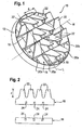
- FIG. 1 shows a stationary mixing element 10 according to the invention, which has a limited by an annular frame 12 grid 14, which is formed by a plurality of parallel aligned first webs 16 and perpendicular thereto second webs 18.
- the first webs 16 define a plurality of mutually parallel rows 20a, 20b, wherein the two outermost rows 20b are bounded on the outside by the frame 12 itself.
- deflection elements 22 From the grid 14 are a plurality of deflection elements 22 from which are attached to the second webs 18, in particular integrally with these (and thus with the grid 14) are formed.
- the length I of the deflection elements 22 substantially corresponds to the width b of the rows 20a, 20b.
- the first webs 16 and the second webs 18, together with the deflecting elements 22, are produced as metal stamped parts. How out FIG. 2 As can be seen, both the first webs 16 and the second webs 18 a plurality of slots 24 through which the first and the second webs 16 and 18 are inserted into one another. Subsequently, the grid 14 is welded or soldered together at the crossing points, and the frame 12 is welded or soldered to the grid 14.
- the edges of the mixing element 10 are formed sharp-edged, which is e.g. can be achieved that takes place after punching no post-machining.
- the baffles 22 which are trapezoidal and taper away from the grid 14, out of the grid plane normal N in the longitudinal direction L by 10 ° 60 °, here preferably about 45 °, bent so that the deflecting elements 22 are inclined relative to the lattice plane normal N in the finished mixing element 10.
- all the deflecting elements 22 of a row 20a, 20b are inclined in the same direction and also have the same inclination angle ⁇ to the grid plane normal N.
- the deflecting elements in a peripheral region of the grid 14 may have a different angle of inclination than the deflecting elements in one middle range.
- the deflecting elements 22 of the two immediately adjacent first rows 20a which here form the middle rows, are inclined in the same direction, and the deflecting elements 22 of the first rows 20a adjacent second rows 20b (here the outer rows) are inclined in opposite directions.
- each two (perpendicular to the row longitudinal direction L) adjacent baffles 22 of the first rows 20a are aligned parallel to each other.
- the opposite inclination of the deflector 22 in the first and second rows is achieved in that, based on the illustration in FIG. 2 for example, the two middle deflecting elements 22 (belonging to the first rows 20a) are bent out of the drawing plane and the two adjacent outer deflecting elements 22 are bent into the drawing plane.
- the grating 14 has exactly two middle or first rows 20a, but it may also be more first rows 20a whose deflecting elements 22 are inclined in the same direction. It is only decisive that a plurality of first rows 20a are arranged directly adjacent to one another with deflecting elements 22 inclined in the same direction and adjoin at least one, possibly also a plurality of outer row (s) 20b at their outer edge, which are inclined in opposite directions. It should also be emphasized that the baffles 22 project downstream from the grid 14.
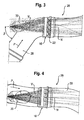
- FIGS. 3 and 4 show a detail of an exhaust system 26 according to the invention for an internal combustion engine, in particular a motor vehicle engine, which has a flue-gas exhaust pipe 28 and a feeder 30 for a reducing agent, in this case aqueous urea solution.
- a reducing agent in this case aqueous urea solution.
- the mixing element 10 is positioned with the deflector elements 22 positioned on the downstream side of the grate 14.
- the lattice plane normal N coincides with the longitudinal axis of the tube 28 on the downstream side.
- an SCR catalyst not shown in the figures is provided downstream.
- the tube 28 Upstream of the mixing element 10, ie on the side facing away from the deflecting elements 22, the tube 28 is angled relative to the grid plane normal N by 15 ° to 60 ° (angle ⁇ ), here by about 45 °. How out FIG. 3 As can be seen, the tube 28 is angled along the rows 20a, 20b, that is, the exhaust gas strikes approximately perpendicular to the downward in the figure deflecting elements 22 of the first rows 20a. The supply of the reducing agent, however, takes place at an angle between 15 ° and 60 ° to the inflow direction of the exhaust gas.
- aqueous urea solution (distribution trajectories V) is introduced to reduce nitrogen oxides contained in the exhaust gas via the feeder 30, which is finely distributed and vaporized by the mixing element 10.
- the deflecting elements 22 or the entire mixing element 10 may have a catalytically active coating (not shown).
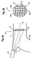
- FIGS. 5a and 5b again show a schematic opposite to the FIGS. 3 and 4 slightly modified exhaust system 26 and the orientation of the associated mixing element 10, that of the FIG. 1 equivalent.
- This mixing element 10 is particularly suitable for non-axial supply of the reducing agent (the supply of the reducing agent takes place here at an angle ⁇ to the grid plane normal N).
- the mixing elements 10 of the FIGS. 1 or 5 axisymmetric to at least one central axis are formed.
Landscapes
- Chemical & Material Sciences (AREA)
- Chemical Kinetics & Catalysis (AREA)
- Engineering & Computer Science (AREA)
- Dispersion Chemistry (AREA)
- Health & Medical Sciences (AREA)
- Toxicology (AREA)
- Combustion & Propulsion (AREA)
- Mechanical Engineering (AREA)
- General Engineering & Computer Science (AREA)
- Exhaust Gas After Treatment (AREA)
- Cylinder Crankcases Of Internal Combustion Engines (AREA)
Description
- Die Erfindung betrifft ein Mischelement, insbesondere zur Anordnung in einer Abgasanlage einer Verbrennungskraftmaschine, mit einem Gitter, das mehrere zueinander parallele Reihen aufweist, und mehreren vom Gitter abstehenden Ablenkelementen, die gegenüber der Gitterebenen-Normalen geneigt sind, wobei sämtliche Ablenkelemente einer Reihe gleichsinnig geneigt sind. Gemäß einem weiteren Aspekt betrifft die Erfindung ein Mischelement mit einem Gitter, das mehrere zueinander parallele Reihen aufweist, und mehreren vom Gitter abstehenden Ablenkelementen, die gegenüber der Gitterebenen-Normalen geneigt sind, wobei mindestens ein Feld mit gleichsinnig geneigten Ablenkelementen vorgesehen ist, das durch wenigstens vier benachbarte Ablenkelemente gebildet wird. Ein dritter Aspekt der Erfindung sieht ein Mischelement vor, mit einem Gitter, das mehrere zueinander parallele Reihen aufweist, und mehreren vom Gitter abstehenden Ablenkelementen, die gegenüber der Gitterebenen-Normalen geneigt sind. Außerdem betrifft die Erfindung eine Abgasanlage für eine Verbrennungskraftmaschine.
- Ein gattungsbildendes Mischelement ist aus der
DE 43 13 393 C2 bekannt und dient dazu, ein in eine Rohrleitung eingebrachtes Medium möglichst homogen in einem Strömungsmedium zu verteilen. Insbesondere wird das Mischelement zur Vermischung eines stickoxidhaltigen Abgasstroms mit Ammoniak verwendet. In einem nachgeschalteten DeNOx-Katalysator werden die Stickoxide und das Ammoniak nach dem Verfahren der selektiven katalytischen Reduktion katalytisch in Wasser und Stickstoff umgesetzt. Bei dem im Stand der Technik beschriebenen Mischelement sind die Ablenkelemente unmittelbar benachbarter Reihen gegenläufig geneigt sowie zueinander versetzt angeordnet. -
- Die Erfindung schafft ein Mischelement, das sich gegenüber dem Stand der Technik durch eine verbesserte Vermischung eines eingebrachten Stoffs mit einem Strömungsmedium auszeichnet.
- Gemäß der Erfindung wird dies bei einem Mischelement nach Anspruch 1 erreicht. Gemäß der erfindung sind die Ablenkelemente der an die ersten Reihen angrenzenden Reihen zu denen der ersten Reihen gegensinnig geneigt. Entscheidend ist generell, daß mindestens zwei benachbarte Reihen gleichsinnig geneigte Ablenkelemente aufweisen. In Tests hat man völlig überraschend herausgefunden, daß das erfindungsgemäße Mischelement, obwohl die Ablenkelemente der benachbarten ersten Reihen gleich geneigt sind, bessere Vermischwerte erreicht als das Mischelement im Stand der Technik. Ferner ist das Mischelement einfacher herzustellen, denn für das Abkanten der eng aneinanderstehenden Ablenkelemente ist es einfacher, wenn benachbarte Ablenkelemente in die gleiche Richtung gebogen werden können. Durch die Erfindung läßt sich insbesondere eine gleichmäßigere Verteilung eines flüssigen Mediums in einem Gasstrom erreichen. Dies ist vor allem bei einer Abgasanlage einer Verbrennungskraftmaschine mit einem sogenannten SCR-Katalysator von Vorteil, der zur Umwandlung von Stickoxiden Ammoniak benötigt. Zu diesem Zweck wird eine wäßrige Harnstofflösung in die Abgasanlage eingebracht, wobei es entscheidend ist, daß selbst die größten Tropfen der Harnstofflösung stromaufwärts des SCR-Katalysators verdampft und durch Thermolyse in Ammoniakgas umgewandelt werden. Verbleibende Tropfen könnten das Katalysatorsubstrat schädigen oder sich an den kälteren Wänden des abgasdurchströmten Rohres festsetzen. Der abgelagerte Harnstoff kann in Folge abplatzen und den Katalysator beschädigen. Dies wird durch das erfindungsgemäße Mischelement verhindert. Aufgrund ihrer geringen thermisch wirksamen Masse heizen sich die Ablenkelemente im heißen Abgasstrom schnell auf, und kleine Tröpfchen werden verdampft, wenn sie die Oberfläche der Ablenkelemente treffen. Größere Tropfen treffen auf die Oberfläche der Ablenkelemente und bersten aufgrund ihrer hohen kinetischen Energie in viele kleine Tröpfchen, die ebenfalls zuverlässig verdampft werden. Die in der vorliegenden Erfindung beschriebene Ausrichtung der Reihen muß nicht zwingend zu einer ganz exakten Parallelausrichtung führen. Eine leichte Schrägstellung ist durchaus möglich.
- Vorzugsweise sind die nebeneinanderliegenden Ablenkelemente der ersten Reihen parallel zueinander ausgerichtet. Hierbei sind unter den nebeneinanderliegenden Ablenkelementen diejenigen zu verstehen, die senkrecht zur Reihenlängsrichtung unmittelbar nebeneinander liegen.
- Gemäß einer bevorzugten Ausführungsform der Erfindung handelt es sich bei den ersten Reihen um mittlere Reihen, die besonders stark durchströmt werden.
- Alternativ kann es sich bei den ersten Reihen um Reihen handeln, die auf derselben Seite einer parallel zur Reihenlängsrichtung verlaufenden Mittelachse angeordnet, also relativ zur Mittelachse seitlich verschoben sind.
- Die Ablenkelemente können in Reihenlängsrichtung geneigt sein.
- Ebenso ist es denkbar, daß die Ablenkelemente senkrecht zur Reihenlängsrichtung geneigt sind.
- Im letzteren Fall können die freien Enden der Ablenkelemente, je nach gewünschter Strömungsbeeinflussung, zur Mittelachse hin oder von dieser weg zeigen.
- Vorzugsweise weist das Gitter genau zwei erste Reihen auf.
- Je nach gewünschter Verwirbelung können sämtliche Ablenkelemente einer Reihe den gleichen Neigungswinkel aufweisen.
- Eine besonders gleichmäßige Vermischung der Medien läßt sich z.B. dadurch erreichen, daß das Mischelement achsensymmetrisch zu einer parallel zur Reihenlängsrichtung verlaufenden Mittelachse ausgebildet ist.
- Der Neigungswinkel der Ablenkelemente sollte zwischen 10° und 60° zur Gitterebenen-Normalen betragen, vorzugsweise etwa 45°. Auf diese Weise wird eine hohe Verwirbelung und damit eine gute Vermischung der Medien erreicht. Gleichzeitig ist der durch ein derart ausgebildetes Mischelement erzeugte Gegendruck im Strömungsmedium vergleichsweise gering.
- Eine besonders einfache und damit kostengünstig herstellbare Ausgestaltung ergibt sich dadurch, daß das Gitter durch mehrere flache erste und zweite Stege gebildet ist, wobei die ersten Stege senkrecht zu den zweiten Stegen angeordnet sind.
- Vorzugsweise begrenzen die ersten Stege die Reihen, und die Ablenkelemente sind an den zweiten Stegen befestigt. Ebenso können die Ablenkelemente auch an den ersten Reihen befestigt sein, insbesondere bei Ablenkelementen, die senkrecht zur Reihenlängsrichtung geneigt sind.
- Geringe Fertigungskosten werden beim erfindungsgemäßen Mischelement dadurch erreicht, daß die ersten und die zweiten Stege ineinander gesteckt und miteinander verschweißt oder verlötet sind.
- Die Ablenkelemente können einstückig mit dem Gitter ausgebildet sein. Alternativ sind die Ablenkelemente durch Schweißen oder Löten mit dem Gitter verbunden.
- Insbesondere sind die Ablenkelemente (und gegebenenfalls die zugehörigen Stege) als Metallstanzteile ausgebildet.
- Eine für die Vermischung der Medien besonders günstige starke Verwirbelung läßt sich erreichen, wenn die Kanten der Ablenkelemente scharfkantig ausgeführt sind, d.h. ohne spanende Nachbearbeitung nach dem Stanzen.
- Um den durch das Mischelement erzeugten Gegendruck gering zu halten und gleichzeitig die Bildung von Sekundärwirbeln zu begünstigen, können sich die Ablenkelemente in Richtung vom Gitter weg verjüngen.
- Insbesondere sind die Ablenkelemente trapezförmig ausgebildet, wobei die Basis des Trapezes mit dem Gitter verbunden ist.
- Die Länge der Ablenkelemente entspricht im wesentlichen der Breite der Reihen oder hat zumindest die gleiche Größenordnung.
- Natürlich können die Ablenkelemente im Randbereich des Gitters einen anderen Neigungswinkel als diejenigen im mittleren Bereich aufweisen. Auf diese Weise läßt sich die durch das Mischelement erreichte Vermischung gezielt beeinflussen.
- Um die chemische Umsetzung beispielsweise von Harnstofflösung in Ammoniak zu verbessern, können die Ablenkelemente eine katalytisch aktive Beschichtung aufweisen.
- Das erfindungsgemäße Mischelement wird vorzugsweise in einer Abgasanlage für eine Verbrennungskraftmaschine eingesetzt, die neben dem oben beschriebenen Mischelement ein abgasdurchströmtes Rohr sowie eine Zuführeinrichtung für ein Reduktionsmittel aufweist. Insbesondere ist das Mischelement stromabwärts der Zuführeinrichtung angeordnet.
- Wie sich gezeigt hat, läßt sich eine besonders gute Vermischung des Reduktionsmittels mit dem Abgasstrom dadurch erreichen, daß das Rohr stromaufwärts des Mischelements abgewinkelt ist. Auf diese Weise wird das Abgas unmittelbar stromaufwärts des Mischelements zu einer Richtungsänderung gezwungen. Dies ist jedoch nicht in jedem Anwendungsfall zwingend.
- Vorzugsweise ist das Rohr gegenüber der Gitterebenen-Normalen zwischen 15° und 60° abgewinkelt.
- Die Zuführung des Reduktionsmittels erfolgt insbesondere unter einem Winkel zwischen 15° und 60° zur Zuströmrichtung des Abgases. Ziel ist hierbei eine vollständige Benetzung aller Ablenkelemente in jedem Betriebspunkt.
- Weitere Merkmale und Vorteile der Erfindung ergeben sich aus der nachfolgenden Beschreibung einer bevorzugten Ausführungsform anhand der beigefügten Zeichnungen. In diesen zeigen:
-
Figur 1 eine perspektivische Ansicht eines Mischelements gemäß einer ersten Ausführungsform der Erfindung; -
Figur 2 Ansichten eines ersten und eines zweiten Stegs, die das Gitter des Mischelements ausFigur 1 bilden; -
Figur 3 eine Seitenansicht einer erfindungsgemäßen Abgasanlage mit dem Mischelement ausFigur 1 ; -
Figur 4 eine Draufsicht auf die Abgasanlage ausFigur 3 ; und - die
Figuren 5 a und b eine Schnittansicht einer gegenüberFigur 3 leicht abgewandelten Abgasanlage bzw. eine Ansicht des Mischelements ausFigur 1 ; -
Figur 1 zeigt ein erfindungsgemäßes stationäres Mischelement 10, das ein von einem ringförmigen Rahmen 12 begrenztes Gitter 14 aufweist, das durch mehrere parallel ausgerichtete erste Stege 16 und hierzu senkrecht angeordnete zweite Stege 18 gebildet ist. Die ersten Stege 16 begrenzen mehrere zueinander parallele Reihen 20a, 20b, wobei die beiden äußersten Reihen 20b außenseitig durch den Rahmen 12 selbst begrenzt werden. Natürlich wäre es ebenso möglich, die Reihen 20a, 20b nicht exakt parallel auszubilden. - Vom Gitter 14 stehen mehrere Ablenkelemente 22 ab, die an den zweiten Stegen 18 befestigt sind, insbesondere einstückig mit diesen (und damit mit dem Gitter 14) ausgebildet sind. Die Länge I der Ablenkelemente 22 entspricht im wesentlichen der Breite b der Reihen 20a, 20b.
- Zur Herstellung des Mischelements 10 werden die ersten Stege 16 und die zweiten Stege 18 mitsamt den Ablenkelementen 22 als Metallstanzteile gefertigt. Wie aus
Figur 2 hervorgeht, weisen sowohl die ersten Stege 16 als auch die zweiten Stege 18 mehrere Schlitze 24 auf, über die die ersten und die zweiten Stege 16 bzw. 18 ineinander gesteckt werden. Anschließend wird das Gitter 14 an den Kreuzungspunkten miteinander verschweißt bzw. verlötet, und der Rahmen 12 wird an das Gitter 14 angeschweißt bzw. -gelötet. - Insbesondere im Bereich der Ablenkelemente 22 sind die Kanten des Mischelements 10 scharfkantig ausgebildet, was z.B. dadurch erreicht werden kann, daß nach dem Stanzen keine spanende Nachbearbeitung stattfindet.
- Entweder vor oder nach dem Zusammensetzen der ersten und der zweiten Stege 16, 18 zum Gitter 14 werden die Ablenkelemente 22, die trapezförmig ausgebildet sind und sich in Richtung vom Gitter 14 weg verjüngen, aus der Gitterebenen-Normalen N in Reihenlängsrichtung L um 10° bis 60°, hier vorzugsweise etwa 45°, gebogen, so daß beim fertigen Mischelement 10 die Ablenkelemente 22 gegenüber der Gitterebenen-Normalen N geneigt sind. Dabei sind sämtliche Ablenkelemente 22 einer Reihe 20a, 20b gleichsinnig geneigt und haben zudem den gleichen Neigungswinkel α zur Gitterebenen-Normalen N. In einer alternativen, nicht gezeigten Ausgestaltung können die Ablenkelemente in einem Randbereich des Gitters 14 einen anderen Neigungswinkel aufweisen als die Ablenkelemente in einem mittleren Bereich.
- Wie aus
Figur 1 hervorgeht, sind die Ablenkelemente 22 der beiden unmittelbar nebeneinanderliegenden ersten Reihen 20a, die hier die mittleren Reihen bilden, gleichsinnig geneigt, und die Ablenkelemente 22 der an die ersten Reihen 20a angrenzenden zweiten Reihen 20b (hier die äußeren Reihen) sind dazu gegensinnig geneigt. Insbesondere sind je zwei (senkrecht zur Reihenlängsrichtung L) nebeneinanderliegende Ablenkelemente 22 der ersten Reihen 20a parallel zueinander ausgerichtet. Die gegenläufige Neigung der Ablenkelemente 22 in den ersten und zweiten Reihen wird dadurch erreicht, daß, bezogen auf die Darstellung inFigur 2 , die beiden mittleren Ablenkelemente 22 (die zu den ersten Reihen 20a gehören) z.B. aus der Zeichenebene heraus und die beiden angrenzenden äußeren Ablenkelemente 22 in die Zeichenebene hinein gebogen werden. - In der gezeigten Ausgestaltung weist das Gitter 14 genau zwei mittlere bzw. erste Reihen 20a auf, es können jedoch auch mehr erste Reihen 20a sein, deren Ablenkelemente 22 gleichsinnig geneigt sind. Entscheidend ist lediglich, daß mehrere erste Reihen 20a mit gleichsinnig geneigten Ablenkelementen 22 unmittelbar nebeneinander angeordnet sind und an ihrem äußeren Rand an wenigstens eine, ggf. auch mehrere äußere Reihe(n) 20b angrenzen, die dazu gegensinnig geneigt sind. Zu betonen ist auch, daß die Ablenkelemente 22 gegenüber dem Gitter 14 nach stromabwärts abstehen.
- Die
Figuren 3 und 4 zeigen ausschnittsweise eine erfindungsgemäße Abgasanlage 26 für eine Verbrennungskraftmaschine, insbesondere einen Kraftfahrzeugmotor, die ein abgasdurchströmtes Rohr 28 sowie eine Zuführeinrichtung 30 für ein Reduktionsmittel, hier wäßrige Harnstofflösung, aufweist. Bezüglich der durch den Pfeil P angedeuteten Strömungsrichtung des Abgases stromabwärts der Zuführeinrichtung 30 ist das Mischelement 10 angeordnet, wobei die Ablenkelemente 22 auf der stromabwärtigen Seite des Gitters 14 positioniert sind. Die Gitterebenen-Normale N fällt auf der stromabwärtigen Seite mit der Längsachse des Rohres 28 zusammen. Stromabwärts des Mischelements 10 ist ein in den Figuren nicht gezeigter SCR-Katalysator vorgesehen. - Stromaufwärts des Mischelements 10, also auf der den Ablenkelementen 22 abgewandten Seite, ist das Rohr 28 gegenüber der Gitterebenen-Normalen N um 15° bis 60° (Winkel β) abgewinkelt, hier um etwa 45°. Wie aus
Figur 3 hervorgeht, ist das Rohr 28 längs der Reihen 20a, 20b abgewinkelt, das heißt, das Abgas trifft in etwa senkrecht auf die in der Figur nach unten weisenden Ablenkelemente 22 der ersten Reihen 20a. Die Zuführung des Reduktionsmittels hingegen erfolgt unter einem Winkel zwischen 15° und 60° zur Zuströmrichtung des Abgases. - Im Betrieb wird zur Reduktion von im Abgas enthaltenen Stickoxiden über die Zuführeinrichtung 30 wäßrige Harnstofflösung (Verteilungsbahnen V) eingebracht, die durch das Mischelement 10 fein verteilt und verdampft wird. Um die Verdampfung der Harnstofflösung und die Umwandlung in Ammoniak zu begünstigen, können die Ablenkelemente 22 bzw. das gesamte Mischelement 10 eine katalytisch aktive Beschichtung aufweisen (nicht gezeigt).
- Die
Figuren 5a und 5b zeigen noch einmal schematisch eine gegenüber denFiguren 3 und 4 geringfügig modifizierte Abgasanlage 26 sowie die Ausrichtung des zugehörigen Mischelements 10, das demjenigen derFigur 1 entspricht. Dieses Mischelement 10 ist insbesondere auch bei nicht axialer Zuführung des Reduktionsmittels geeignet (die Zuführung des Reduktionsmittels erfolgt hier unter einem Winkel γ zur Gitterebenen-Normalen N). - Zusammenfassend läßt sich festhalten, daß die Mischelemente 10 der
Figuren 1 bzw. 5 achsensymmetrisch zu wenigstens einer Mittelachse ausgebildet sind.
Claims (15)
- Mischelement, insbesondere zur Anordnung in einer Abgasanlage (26) einer Verbrennungskraftmaschine, mit
einem Gitter (14), das mehrere zueinander parallele Reihen (20a, 20b) aufweist, und
mehreren vom Gitter (14) abstehenden Ablenkelemente (22), die gegenüber der Gitterebenen-Normalen (N) geneigt sind,
wobei sämtliche Ablenkelemente (22) einer Reihe (20a, 20b) gleichsinnig geneigt sind,
die Ablenkelemente (22) wenigstens zweier unmittelbar nebeneinanderliegender erster Reihen (20a) gleichsinnig geneigt sind und die Ablenkelemente (22) der an die ersten Reihen (20a) angrenzenden Reihen (20b) zu denen der ersten Reihen (20a) gegensinnig geneigt sind. - Mischelement nach Anspruch 1, dadurch gekennzeichnet, daß die nebeneinanderliegenden Ablenkelemente (22) der ersten Reihen (20a) parallel zueinander ausgerichtet sind.
- Mischelement nach Anspruch 1 oder 2, dadurch gekennzeichnet, daß es sich bei den ersten Reihen (20a) um mittlere Reihen handelt.
- Mischelement nach Anspruch 1 oder 2, dadurch gekennzeichnet, daß es sich bei den ersten Reihen (20a) um Reihen handelt, die auf derselben Seite einer parallel zur Reihenlängsrichtung verlaufenden Mittelachse (M) angeordnet sind.
- Mischelement nach einem der Ansprüche 1 bis 4, dadurch gekennzeichnet, daß die Ablenkelemente (22) in Reihenlängsrichtung (L) geneigt sind oder senkrecht zur Reihenlängsrichtung (L) geneigt sind.
- Mischelement nach den Ansprüchen 4 und 5, dadurch gekennzeichnet, daß die freien Enden der Ablenkelemente (22) zur Mittelachse (M) hin zeigen oder von der Mittelachse (M) weg zeigen.
- Mischelement nach einem der vorhergehenden Ansprüche, dadurch gekennzeichnet, das das Gitter (14) genau zwei erste Reihen (20a) aufweist.
- Mischelement nach einem der vorhergehenden Ansprüche, dadurch gekennzeichnet, daß sämtliche Ablenkelemente (22) einer Reihe (20a, 20b) den gleichen Neigungswinkel (α) aufweisen.
- Mischelement nach einem der vorhergehenden Ansprüche, dadurch gekennzeichnet, daß es achsensymmetrisch zu einer parallel zur Reihenlängsrichtung (L) verlaufenden Mittelachse (M, H) ausgebildet ist.
- Mischelement nach einem der vorhergehenden Ansprüche, dadurch gekennzeichnet, daß die Ablenkelemente (22) zwischen 10° und 60°, vorzugsweise etwa 45°, zur Gitterebenen-Normalen (N) geneigt sind.
- Mischelement nach einem der vorhergehenden Ansprüche, dadurch gekennzeichnet, daß die Ablenkelemente (22) als Metallstanzteile ausgebildet sind und dass vorzugsweise die Kanten der Ablenkelemente (22) scharfkantig, ohne spanende Nachbearbeitung nach dem Stanzen ausgeführt sind.
- Mischelement nach einem der vorhergehenden Ansprüche, dadurch gekennzeichnet, daß sich die Ablenkelemente (22) In Richtung vom Gitter (14) weg verjüngen.
- Mischelement nach einem der vorhergehenden Ansprüche, dadurch gekennzeichnet, daß die Länge der Ablenkelemente (22) im wesentlichen der Breite der Reihen (20a, 20b) entspricht.
- Abgasanlage für eine Verbrennungskraftmaschine, mit einem abgasdurchströmten Rohr (28), einer Zuführeinrichtung (30) für ein Reduktionsmittel sowie einem Mischelement (10) nach einem der vorhergehenden Ansprüche.
- Abgasanlage nach Anspruch 14, dadurch gekennzeichnet, daß das Rohr (28) Stromaufwärts des Mischelements (10) gegenüber der Gitterebenen-Normalen (N) zwischen 15° und 60° abgewinkelt ist und/oder die Zuführung des Reduktionsmittels unter einem Winkel zwischen 15° und 60° zur Zuströmrichtung des Abgases erfolgt.
Applications Claiming Priority (2)
| Application Number | Priority Date | Filing Date | Title |
|---|---|---|---|
| DE102006055036.6A DE102006055036B4 (de) | 2006-11-22 | 2006-11-22 | Mischelement sowie Abgasanlage für eine Verbrennungskraftmaschine |
| PCT/EP2007/010087 WO2008061734A1 (de) | 2006-11-22 | 2007-11-21 | Mischelement sowie abgasanlage für eine verbrennungskraftmaschine |
Publications (3)
| Publication Number | Publication Date |
|---|---|
| EP2097625A1 EP2097625A1 (de) | 2009-09-09 |
| EP2097625B1 EP2097625B1 (de) | 2010-05-26 |
| EP2097625B2 true EP2097625B2 (de) | 2015-01-14 |
Family
ID=38961102
Family Applications (1)
| Application Number | Title | Priority Date | Filing Date |
|---|---|---|---|
| EP07846720.6A Active EP2097625B2 (de) | 2006-11-22 | 2007-11-21 | Mischelement sowie abgasanlage für eine verbrennungskraftmaschine |
Country Status (5)
| Country | Link |
|---|---|
| US (1) | US8607555B2 (de) |
| EP (1) | EP2097625B2 (de) |
| AT (1) | ATE469291T1 (de) |
| DE (2) | DE102006055036B4 (de) |
| WO (1) | WO2008061734A1 (de) |
Families Citing this family (68)
| Publication number | Priority date | Publication date | Assignee | Title |
|---|---|---|---|---|
| US7908845B2 (en) * | 2007-04-16 | 2011-03-22 | GM Global Technology Operations LLC | Mixing apparatus for an exhaust after-treatment system |
| WO2008144385A2 (en) | 2007-05-15 | 2008-11-27 | Donaldson Company, Inc. | Exhaust gas flow device |
| DE102007048558A1 (de) * | 2007-10-09 | 2009-04-16 | Audi Ag | Statischer Mischer für eine Abgasanlage eines brennkraftmaschinenbetriebenen Fahrzeugs, insbesondere eines Kraftfahrzeugs |
| US8939638B2 (en) * | 2008-04-21 | 2015-01-27 | Tenneco Automotive Operating Company Inc. | Method for mixing an exhaust gas flow |
| DE102008020827A1 (de) * | 2008-04-25 | 2009-11-05 | Presswerk Struthütten GmbH | Mischer, Verfahren zur Herstellung eines solchen und Mischeranordnung |
| EP2148053B1 (de) | 2008-07-25 | 2014-06-04 | Volkswagen Aktiengesellschaft | Katalysatoranordnung zur Reinigung eines Abgasstroms |
| DE102008050101A1 (de) | 2008-10-06 | 2010-04-08 | Volkswagen Ag | Vorrichtung zur Eindosierung eines Mediums in einem Abgasstrom |
| DE102008034993A1 (de) | 2008-07-25 | 2010-01-28 | Volkswagen Ag | Katalysatoranordnung zur Reinigung eines Abgasstroms |
| EP2342434B1 (de) * | 2008-09-19 | 2012-08-15 | Renault Trucks | Mischvorrichtung in einem abgasrohr |
| DE102008053669A1 (de) * | 2008-10-29 | 2010-05-06 | Emcon Technologies Germany (Augsburg) Gmbh | Abgasanlage für ein Fahrzeug |
| EP2347106B1 (de) * | 2008-11-21 | 2015-04-22 | Bayerische Motoren Werke Aktiengesellschaft | Einrichtung zum mischen und/oder verdampfen eines reduktionsmittels sowie einrichtung zur beaufschlagung eines abgasstroms mit einem reduktionsmittel |
| EP2358982B1 (de) | 2008-12-17 | 2017-11-08 | Donaldson Company, Inc. | Flussvorrichtung für ein abgassystem |
| US8869518B2 (en) * | 2009-09-15 | 2014-10-28 | Tenneco Automotive Operating Company Inc. | Burner for a diesel aftertreatment system |
| EP2512642B1 (de) * | 2009-12-18 | 2014-02-26 | Renault Trucks | Mischsystem in einer abgasnachbehandlungsanordnung |
| EP2524123B1 (de) | 2010-01-12 | 2016-11-23 | Donaldson Company, Inc. | Strömungsvorrichtung für ein abgasbehandlungssystem |
| US9010994B2 (en) * | 2010-01-21 | 2015-04-21 | Fluid Components International Llc | Flow mixer and conditioner |
| US20110174408A1 (en) * | 2010-01-21 | 2011-07-21 | Fluid Components International Llc | Flow mixer and conditioner |
| US8935918B2 (en) * | 2010-04-23 | 2015-01-20 | GM Global Technology Operations LLC | Reconfigurable mixer for an exhaust aftertreatment system and method of using the same |
| US8240135B2 (en) * | 2010-05-07 | 2012-08-14 | Ford Global Technologies, Llc | Exhaust system mixing device |
| EP3267005B2 (de) | 2010-06-22 | 2023-12-27 | Donaldson Company, Inc. | Abgasnachbehandlungsvorrichtung |
| US20120204541A1 (en) * | 2011-02-14 | 2012-08-16 | GM Global Technology Operations LLC | Exhaust mixer element and method for mixing |
| DE102011077645A1 (de) * | 2011-06-16 | 2012-12-20 | Bosch Emission Systems Gmbh & Co. Kg | Statischer Mischer |
| DE102011108237A1 (de) * | 2011-07-21 | 2013-01-24 | Friedrich Boysen Gmbh & Co. Kg | Anordnung zum Einbringen eines Zusatzstoffes in einen Gasstrom |
| DE102011083637B4 (de) | 2011-09-28 | 2016-04-14 | Eberspächer Exhaust Technology GmbH & Co. KG | Misch- und/oder Verdampfungseinrichtung |
| US8938954B2 (en) | 2012-04-19 | 2015-01-27 | Donaldson Company, Inc. | Integrated exhaust treatment device having compact configuration |
| WO2014022386A2 (en) * | 2012-07-31 | 2014-02-06 | Cummins Filtration Ip, Inc. | Methods and apparatuses for separating liquid particles from a gas-liquid stream |
| DE102012016423B3 (de) * | 2012-08-21 | 2014-02-27 | Eberspächer Exhaust Technology GmbH & Co. KG | Abgasanlage mit Misch- und oder Verdampfungseinrichtung |
| JP6105230B2 (ja) * | 2012-08-24 | 2017-03-29 | フタバ産業株式会社 | 排気攪拌装置 |
| DE102012216923B4 (de) * | 2012-09-20 | 2016-01-28 | Eberspächer Exhaust Technology GmbH & Co. KG | Abgasanlage für ein Kraftfahrzeug |
| US9504947B2 (en) | 2012-11-13 | 2016-11-29 | Cummins Filtration Ip, Inc. | Air filter assemblies and carrier frames having vortex-generating flow guide |
| US9707525B2 (en) | 2013-02-15 | 2017-07-18 | Donaldson Company, Inc. | Dosing and mixing arrangement for use in exhaust aftertreatment |
| DE102013208184A1 (de) * | 2013-05-03 | 2014-11-06 | Eberspächer Exhaust Technology GmbH & Co. KG | Abgasanlagenkomponente |
| US20150071826A1 (en) * | 2013-05-07 | 2015-03-12 | Tenneco Automotive Operating Company Inc. | Axial flow atomization module with mixing device |
| FR3010137B1 (fr) | 2013-08-30 | 2016-08-26 | Faurecia Systemes D'echappement | Dispositif de purification de gaz d'echappement de moteur a combustion interne |
| FR3010134A1 (fr) * | 2013-09-04 | 2015-03-06 | Faurecia Sys Echappement | Dispositif perfectionne de purification de gaz d'echappement de moteur a combustion interne |
| DE102013223956A1 (de) * | 2013-11-22 | 2015-05-28 | Robert Bosch Gmbh | Einrichtung zur Abgasnachbehandlung |
| DE102014112004A1 (de) * | 2014-08-21 | 2016-02-25 | Friedrich Boysen Gmbh & Co. Kg | Mischereinrichtung |
| US9447717B2 (en) * | 2014-08-21 | 2016-09-20 | GM Global Technology Operations LLC | Mixer for short mixing lengths |
| US9718037B2 (en) * | 2014-12-17 | 2017-08-01 | Caterpillar Inc. | Mixing system for aftertreatment system |
| JP6535249B2 (ja) * | 2015-08-07 | 2019-06-26 | 日野自動車株式会社 | 尿素水リアクタ |
| DE102015114723A1 (de) * | 2015-09-03 | 2017-03-09 | Eberspächer Exhaust Technology GmbH & Co. KG | Abgasanlage für eine Brennkraftmaschine |
| US20160032810A1 (en) * | 2015-10-16 | 2016-02-04 | Caterpillar Inc. | Mixer for exhaust gas aftertreatment system |
| US9714597B2 (en) * | 2015-12-03 | 2017-07-25 | GM Global Technology Operations LLC | Exhaust mixer for compact system |
| US10012125B2 (en) | 2016-05-02 | 2018-07-03 | Caterpillar Inc. | Dual mixer for exhaust aftertreatment systems |
| US9909478B2 (en) | 2016-05-02 | 2018-03-06 | Caterpillar Inc. | Mixer for exhaust aftertreatment systems |
| GB2566907B (en) | 2016-07-07 | 2021-09-22 | Caterpillar Inc | Dual mixer for exhaust gas aftertreatment systems |
| WO2018107268A1 (en) * | 2016-12-12 | 2018-06-21 | Canada Pipeline Accessories, Co. Ltd. | Static mixer for fluid flow in a pipeline |
| KR102089126B1 (ko) * | 2017-05-24 | 2020-03-13 | 주식회사 엘지화학 | 선택적 촉매 환원 시스템 |
| WO2018226626A1 (en) | 2017-06-06 | 2018-12-13 | Cummins Emission Solutions Inc. | Systems and methods for mixing exhaust gases and reductant in an aftertreatment system |
| US10801500B2 (en) * | 2017-08-24 | 2020-10-13 | Ingersoll-Rand Industrial U.S., Inc. | Compressor system separator tank baffle |
| GB2581919B (en) | 2018-05-07 | 2023-03-15 | Canada Pipeline Access Co Ltd | Pipe assembly with static mixer and flow conditioner |
| US11208934B2 (en) | 2019-02-25 | 2021-12-28 | Cummins Emission Solutions Inc. | Systems and methods for mixing exhaust gas and reductant |
| US11448160B2 (en) | 2019-09-23 | 2022-09-20 | General Electric Company | High temperature gradient gas mixer |
| BR112022010295A2 (pt) | 2019-12-03 | 2022-08-09 | Cummins Emission Solutions Inc | Sistema de liberação de redutor para sistema de pós-tratamento de gás de escape |
| USD976384S1 (en) | 2020-01-13 | 2023-01-24 | Canada Pipeline Accessories Co., Ltd. | Static mixer for fluid flow |
| CN115135404A (zh) | 2020-02-27 | 2022-09-30 | 康明斯排放处理公司 | 用于后处理系统中的混合器 |
| GB2609163B (en) | 2020-05-08 | 2023-08-23 | Cummins Emission Solutions Inc | Configurable aftertreatment systems including a housing |
| US11247173B1 (en) * | 2020-08-11 | 2022-02-15 | Caterpillar Inc. | Two-stage mixer |
| US11268423B1 (en) * | 2020-09-10 | 2022-03-08 | Tenneco Automotive Operating Company Inc. | Two-part two-stage mixer |
| DE112021005606T5 (de) | 2020-10-22 | 2023-08-17 | Cummins Emission Solutions Inc. | Abgasnachbehandlungssystem |
| GB2630900B (en) | 2021-02-02 | 2025-07-02 | Cummins Emission Solutions Inc | Exhaust gas aftertreatment systems |
| US12123337B2 (en) | 2021-03-18 | 2024-10-22 | Cummins Emission Solutions Inc. | Aftertreatment systems |
| US11285448B1 (en) * | 2021-04-12 | 2022-03-29 | William J. Lund | Static mixer inserts and static mixers incorporating same |
| CN114961930B (zh) * | 2021-06-11 | 2024-12-20 | 无锡威孚力达催化净化器有限责任公司 | 一种高效混合管道装置 |
| US12281605B2 (en) | 2021-07-27 | 2025-04-22 | Cummins Emision Solutions Inc. | Exhaust gas aftertreatment system |
| GB2626449B (en) | 2021-08-23 | 2025-07-16 | Cummins Emission Solutions Inc | Outlet sampling system for aftertreatment system |
| USD1042544S1 (en) | 2022-04-21 | 2024-09-17 | Cummins Emission Solutions Inc. | Aftertreatment system |
| USD1042545S1 (en) | 2022-04-21 | 2024-09-17 | Cummins Emission Solutions Inc. | Aftertreatment system |
Citations (1)
| Publication number | Priority date | Publication date | Assignee | Title |
|---|---|---|---|---|
| DE10123358A1 (de) † | 2001-05-14 | 2002-11-21 | Man Nutzfahrzeuge Ag | Abgasstrang einer Brennkraftmaschine, insbesondere Dieselmotor eines Nutzfahrzeuges wie Lastkraftwagen oder Omnibus, mit integrierten Abgasnachbehandlungs- und Schalldämpfungsvorrichtungen |
Family Cites Families (19)
| Publication number | Priority date | Publication date | Assignee | Title |
|---|---|---|---|---|
| US4530418A (en) * | 1982-06-01 | 1985-07-23 | Currie Neil L | Automotive exhaust system |
| JPS60179101A (ja) | 1984-02-28 | 1985-09-13 | Ngk Insulators Ltd | 流体接触用多孔体 |
| DE4109305A1 (de) | 1991-03-21 | 1992-09-24 | Siemens Ag | Einrichtung zum einbringen eines reaktionsmittels in einen gasstrom |
| DE4123161A1 (de) | 1991-07-12 | 1993-01-14 | Siemens Ag | Statischer mischer |
| DE4313393C2 (de) | 1993-04-07 | 2003-06-26 | Siemens Ag | Statischer Mischer |
| EP0864732B1 (de) * | 1997-03-13 | 2003-02-26 | Haldor Topsoe A/S | Verfahren zur selektiven Reduktion von NOx in Abgas |
| DE19731865C2 (de) * | 1997-07-24 | 1999-05-06 | Siemens Ag | Abgasreinigungsanlage für das Abgas eines Dieselmotors |
| DE19741199C2 (de) | 1997-09-18 | 2000-10-26 | Siemens Ag | Statischer Mischer |
| DE19924029C2 (de) * | 1999-05-26 | 2001-05-23 | Porsche Ag | Verfahren zur Überwachung der Funktion eines Systems zur Abgasnachbehandlung |
| EP1371824A1 (de) | 2002-06-11 | 2003-12-17 | Siemens Aktiengesellschaft | Vorrichtung zur Reinigung des Abgases einer Verbrennungsanlage |
| EP1424488A1 (de) | 2002-11-26 | 2004-06-02 | David Burnett | Wirbelspinnvorrichtung für ein Kraftfahrzeug |
| EP2256313B1 (de) * | 2004-07-16 | 2012-03-14 | Nissan Diesel Motor Co., Ltd. | Abgasreinigungsvorrichtung für einen Verbrennungsmotor |
| US7581387B2 (en) * | 2005-02-28 | 2009-09-01 | Caterpillar Inc. | Exhaust gas mixing system |
| ITMI20050653A1 (it) * | 2005-04-15 | 2006-10-16 | Iveco Spa | Modulo di miscelazione per un fluido in una corrente di gas |
| ITMI20050655A1 (it) | 2005-04-15 | 2006-10-16 | Iveco Spa | Miscelatore statico |
| DE102005063081A1 (de) | 2005-12-29 | 2007-07-05 | Robert Bosch Gmbh | Einbauteil zur Montage in einem Abgasstrang einer Verbrennungskraftmaschine |
| DE102006024778B3 (de) | 2006-03-02 | 2007-07-19 | J. Eberspächer GmbH & Co. KG | Statischer Mischer und Abgasbehandlungseinrichtung |
| US7533520B2 (en) * | 2006-04-24 | 2009-05-19 | Fleetguard, Inc. | Exhaust aftertreatment mixer with stamped muffler flange |
| US7908845B2 (en) * | 2007-04-16 | 2011-03-22 | GM Global Technology Operations LLC | Mixing apparatus for an exhaust after-treatment system |
-
2006
- 2006-11-22 DE DE102006055036.6A patent/DE102006055036B4/de active Active
-
2007
- 2007-11-21 AT AT07846720T patent/ATE469291T1/de active
- 2007-11-21 WO PCT/EP2007/010087 patent/WO2008061734A1/de not_active Ceased
- 2007-11-21 US US12/515,595 patent/US8607555B2/en active Active
- 2007-11-21 DE DE502007003975T patent/DE502007003975D1/de active Active
- 2007-11-21 EP EP07846720.6A patent/EP2097625B2/de active Active
Patent Citations (1)
| Publication number | Priority date | Publication date | Assignee | Title |
|---|---|---|---|---|
| DE10123358A1 (de) † | 2001-05-14 | 2002-11-21 | Man Nutzfahrzeuge Ag | Abgasstrang einer Brennkraftmaschine, insbesondere Dieselmotor eines Nutzfahrzeuges wie Lastkraftwagen oder Omnibus, mit integrierten Abgasnachbehandlungs- und Schalldämpfungsvorrichtungen |
Also Published As
| Publication number | Publication date |
|---|---|
| EP2097625A1 (de) | 2009-09-09 |
| US20100107617A1 (en) | 2010-05-06 |
| EP2097625B1 (de) | 2010-05-26 |
| DE102006055036A1 (de) | 2008-05-29 |
| ATE469291T1 (de) | 2010-06-15 |
| DE502007003975D1 (de) | 2010-07-08 |
| DE102006055036B4 (de) | 2023-03-02 |
| US8607555B2 (en) | 2013-12-17 |
| WO2008061734A1 (de) | 2008-05-29 |
Similar Documents
| Publication | Publication Date | Title |
|---|---|---|
| EP2097625B2 (de) | Mischelement sowie abgasanlage für eine verbrennungskraftmaschine | |
| DE102007009890B4 (de) | Statisches Mischelement sowie Verfahren zur Herstellung eines statischen Mischelements | |
| EP2820260B1 (de) | Vorrichtung zur abgasreinigung | |
| EP2205345B1 (de) | Statischer mischer für eine abgasanlage eines brennkraftmaschinenbetriebenen fahrzeugs, insbesondere kraftfahrzeugs | |
| EP2700442B1 (de) | Abgasanlage mit Misch- und/oder Verdampfungseinrichtung | |
| DE112013004008B4 (de) | Vorrichtung zum Mischen eines Abgasstroms | |
| EP3071807B1 (de) | Abgasnachbehandlungseinrichtung | |
| DE102008029110A1 (de) | Misch- und/oder Verdampfungseinrichtung | |
| EP2535535A1 (de) | Statischer Mischer | |
| DE102016115030A1 (de) | Abgasmischelement | |
| DE102008017395B4 (de) | Misch- und/oder Verdampfungseinrichtung und zugehöriges Herstellungsverfahren | |
| EP2111917A1 (de) | Statischer Mischer, Verfahren zur Herstellung eines solchen und Mischeranordnung | |
| DE102007002981A1 (de) | Statischer Mischer für eine Abgasanlage eines brennkraftmaschinenbetriebenen Fahrzeugs, insbesondere Kraftfahrzeugs | |
| DE112014005413T5 (de) | Abgasstrommischer | |
| EP3611354B1 (de) | Mischer | |
| DE102020101226A1 (de) | Vorrichtung zum Einbringen und Verteilen einer Flüssigkeit in einen Gasstrom | |
| DE10239417A1 (de) | Heißgas-Strömungskanal, insbesondere innerhalb einer Abgasanlage eines Verbrennungsmotors stromauf eines Katalysators | |
| WO2013087850A1 (de) | Mischereinrichtung | |
| DE102019103780B4 (de) | Mischer | |
| DE102019208824A1 (de) | Abgasstrang zur Abgasnachbehandlung | |
| WO2013087852A2 (de) | Mischereinrichtung | |
| DE102014222395B4 (de) | Abgasanlage und Verfahren zur Herstellung einer solchen | |
| DE102008026724B4 (de) | Verschluss für ein Rohr oder eine Platine | |
| DE102012004291A1 (de) | Vorrichtung zur Abgasreinigung | |
| DE102017216993B3 (de) | Mischeinrichtung |
Legal Events
| Date | Code | Title | Description |
|---|---|---|---|
| PUAI | Public reference made under article 153(3) epc to a published international application that has entered the european phase |
Free format text: ORIGINAL CODE: 0009012 |
|
| 17P | Request for examination filed |
Effective date: 20090622 |
|
| AK | Designated contracting states |
Kind code of ref document: A1 Designated state(s): AT BE BG CH CY CZ DE DK EE ES FI FR GB GR HU IE IS IT LI LT LU LV MC MT NL PL PT RO SE SI SK TR |
|
| RIN1 | Information on inventor provided before grant (corrected) |
Inventor name: STADLER, FLORIAN Inventor name: RUSCH, KLAUS Inventor name: KAISER, ROLF |
|
| 17Q | First examination report despatched |
Effective date: 20090922 |
|
| GRAP | Despatch of communication of intention to grant a patent |
Free format text: ORIGINAL CODE: EPIDOSNIGR1 |
|
| DAX | Request for extension of the european patent (deleted) | ||
| GRAS | Grant fee paid |
Free format text: ORIGINAL CODE: EPIDOSNIGR3 |
|
| GRAA | (expected) grant |
Free format text: ORIGINAL CODE: 0009210 |
|
| AK | Designated contracting states |
Kind code of ref document: B1 Designated state(s): AT BE BG CH CY CZ DE DK EE ES FI FR GB GR HU IE IS IT LI LT LU LV MC MT NL PL PT RO SE SI SK TR |
|
| REG | Reference to a national code |
Ref country code: GB Ref legal event code: FG4D Free format text: NOT ENGLISH |
|
| REG | Reference to a national code |
Ref country code: CH Ref legal event code: EP |
|
| REG | Reference to a national code |
Ref country code: IE Ref legal event code: FG4D Free format text: LANGUAGE OF EP DOCUMENT: GERMAN |
|
| REF | Corresponds to: |
Ref document number: 502007003975 Country of ref document: DE Date of ref document: 20100708 Kind code of ref document: P |
|
| REG | Reference to a national code |
Ref country code: NL Ref legal event code: VDEP Effective date: 20100526 |
|
| LTIE | Lt: invalidation of european patent or patent extension |
Effective date: 20100526 |
|
| PG25 | Lapsed in a contracting state [announced via postgrant information from national office to epo] |
Ref country code: SE Free format text: LAPSE BECAUSE OF FAILURE TO SUBMIT A TRANSLATION OF THE DESCRIPTION OR TO PAY THE FEE WITHIN THE PRESCRIBED TIME-LIMIT Effective date: 20100526 Ref country code: LT Free format text: LAPSE BECAUSE OF FAILURE TO SUBMIT A TRANSLATION OF THE DESCRIPTION OR TO PAY THE FEE WITHIN THE PRESCRIBED TIME-LIMIT Effective date: 20100526 |
|
| PG25 | Lapsed in a contracting state [announced via postgrant information from national office to epo] |
Ref country code: SI Free format text: LAPSE BECAUSE OF FAILURE TO SUBMIT A TRANSLATION OF THE DESCRIPTION OR TO PAY THE FEE WITHIN THE PRESCRIBED TIME-LIMIT Effective date: 20100526 Ref country code: LV Free format text: LAPSE BECAUSE OF FAILURE TO SUBMIT A TRANSLATION OF THE DESCRIPTION OR TO PAY THE FEE WITHIN THE PRESCRIBED TIME-LIMIT Effective date: 20100526 Ref country code: IS Free format text: LAPSE BECAUSE OF FAILURE TO SUBMIT A TRANSLATION OF THE DESCRIPTION OR TO PAY THE FEE WITHIN THE PRESCRIBED TIME-LIMIT Effective date: 20100926 Ref country code: FI Free format text: LAPSE BECAUSE OF FAILURE TO SUBMIT A TRANSLATION OF THE DESCRIPTION OR TO PAY THE FEE WITHIN THE PRESCRIBED TIME-LIMIT Effective date: 20100526 |
|
| PG25 | Lapsed in a contracting state [announced via postgrant information from national office to epo] |
Ref country code: PL Free format text: LAPSE BECAUSE OF FAILURE TO SUBMIT A TRANSLATION OF THE DESCRIPTION OR TO PAY THE FEE WITHIN THE PRESCRIBED TIME-LIMIT Effective date: 20100526 Ref country code: CY Free format text: LAPSE BECAUSE OF FAILURE TO SUBMIT A TRANSLATION OF THE DESCRIPTION OR TO PAY THE FEE WITHIN THE PRESCRIBED TIME-LIMIT Effective date: 20100616 |
|
| REG | Reference to a national code |
Ref country code: IE Ref legal event code: FD4D |
|
| PG25 | Lapsed in a contracting state [announced via postgrant information from national office to epo] |
Ref country code: DK Free format text: LAPSE BECAUSE OF FAILURE TO SUBMIT A TRANSLATION OF THE DESCRIPTION OR TO PAY THE FEE WITHIN THE PRESCRIBED TIME-LIMIT Effective date: 20100526 Ref country code: NL Free format text: LAPSE BECAUSE OF FAILURE TO SUBMIT A TRANSLATION OF THE DESCRIPTION OR TO PAY THE FEE WITHIN THE PRESCRIBED TIME-LIMIT Effective date: 20100526 Ref country code: EE Free format text: LAPSE BECAUSE OF FAILURE TO SUBMIT A TRANSLATION OF THE DESCRIPTION OR TO PAY THE FEE WITHIN THE PRESCRIBED TIME-LIMIT Effective date: 20100526 Ref country code: IE Free format text: LAPSE BECAUSE OF FAILURE TO SUBMIT A TRANSLATION OF THE DESCRIPTION OR TO PAY THE FEE WITHIN THE PRESCRIBED TIME-LIMIT Effective date: 20100526 Ref country code: PT Free format text: LAPSE BECAUSE OF FAILURE TO SUBMIT A TRANSLATION OF THE DESCRIPTION OR TO PAY THE FEE WITHIN THE PRESCRIBED TIME-LIMIT Effective date: 20100927 |
|
| PG25 | Lapsed in a contracting state [announced via postgrant information from national office to epo] |
Ref country code: CZ Free format text: LAPSE BECAUSE OF FAILURE TO SUBMIT A TRANSLATION OF THE DESCRIPTION OR TO PAY THE FEE WITHIN THE PRESCRIBED TIME-LIMIT Effective date: 20100526 Ref country code: SK Free format text: LAPSE BECAUSE OF FAILURE TO SUBMIT A TRANSLATION OF THE DESCRIPTION OR TO PAY THE FEE WITHIN THE PRESCRIBED TIME-LIMIT Effective date: 20100526 Ref country code: RO Free format text: LAPSE BECAUSE OF FAILURE TO SUBMIT A TRANSLATION OF THE DESCRIPTION OR TO PAY THE FEE WITHIN THE PRESCRIBED TIME-LIMIT Effective date: 20100526 |
|
| PLBI | Opposition filed |
Free format text: ORIGINAL CODE: 0009260 |
|
| PLAX | Notice of opposition and request to file observation + time limit sent |
Free format text: ORIGINAL CODE: EPIDOSNOBS2 |
|
| PG25 | Lapsed in a contracting state [announced via postgrant information from national office to epo] |
Ref country code: IT Free format text: LAPSE BECAUSE OF FAILURE TO SUBMIT A TRANSLATION OF THE DESCRIPTION OR TO PAY THE FEE WITHIN THE PRESCRIBED TIME-LIMIT Effective date: 20100526 |
|
| 26 | Opposition filed |
Opponent name: HEINRICH GILLET GMBH & CO. KG Effective date: 20110228 |
|
| REG | Reference to a national code |
Ref country code: DE Ref legal event code: R026 Ref document number: 502007003975 Country of ref document: DE Effective date: 20110228 |
|
| BERE | Be: lapsed |
Owner name: EMCON TECHNOLOGIES GERMANY (AUGSBURG) G.M.B.H. Effective date: 20101130 |
|
| PG25 | Lapsed in a contracting state [announced via postgrant information from national office to epo] |
Ref country code: GR Free format text: LAPSE BECAUSE OF FAILURE TO SUBMIT A TRANSLATION OF THE DESCRIPTION OR TO PAY THE FEE WITHIN THE PRESCRIBED TIME-LIMIT Effective date: 20100827 |
|
| PG25 | Lapsed in a contracting state [announced via postgrant information from national office to epo] |
Ref country code: MC Free format text: LAPSE BECAUSE OF NON-PAYMENT OF DUE FEES Effective date: 20101130 |
|
| PG25 | Lapsed in a contracting state [announced via postgrant information from national office to epo] |
Ref country code: BE Free format text: LAPSE BECAUSE OF NON-PAYMENT OF DUE FEES Effective date: 20101130 |
|
| PLBB | Reply of patent proprietor to notice(s) of opposition received |
Free format text: ORIGINAL CODE: EPIDOSNOBS3 |
|
| PG25 | Lapsed in a contracting state [announced via postgrant information from national office to epo] |
Ref country code: MT Free format text: LAPSE BECAUSE OF FAILURE TO SUBMIT A TRANSLATION OF THE DESCRIPTION OR TO PAY THE FEE WITHIN THE PRESCRIBED TIME-LIMIT Effective date: 20100526 |
|
| REG | Reference to a national code |
Ref country code: CH Ref legal event code: PL |
|
| GBPC | Gb: european patent ceased through non-payment of renewal fee |
Effective date: 20111121 |
|
| PG25 | Lapsed in a contracting state [announced via postgrant information from national office to epo] |
Ref country code: LI Free format text: LAPSE BECAUSE OF NON-PAYMENT OF DUE FEES Effective date: 20111130 Ref country code: CH Free format text: LAPSE BECAUSE OF NON-PAYMENT OF DUE FEES Effective date: 20111130 |
|
| PG25 | Lapsed in a contracting state [announced via postgrant information from national office to epo] |
Ref country code: LU Free format text: LAPSE BECAUSE OF NON-PAYMENT OF DUE FEES Effective date: 20101121 Ref country code: HU Free format text: LAPSE BECAUSE OF FAILURE TO SUBMIT A TRANSLATION OF THE DESCRIPTION OR TO PAY THE FEE WITHIN THE PRESCRIBED TIME-LIMIT Effective date: 20101127 Ref country code: BG Free format text: LAPSE BECAUSE OF FAILURE TO SUBMIT A TRANSLATION OF THE DESCRIPTION OR TO PAY THE FEE WITHIN THE PRESCRIBED TIME-LIMIT Effective date: 20100526 |
|
| PG25 | Lapsed in a contracting state [announced via postgrant information from national office to epo] |
Ref country code: GB Free format text: LAPSE BECAUSE OF NON-PAYMENT OF DUE FEES Effective date: 20111121 Ref country code: TR Free format text: LAPSE BECAUSE OF FAILURE TO SUBMIT A TRANSLATION OF THE DESCRIPTION OR TO PAY THE FEE WITHIN THE PRESCRIBED TIME-LIMIT Effective date: 20100526 |
|
| PLAB | Opposition data, opponent's data or that of the opponent's representative modified |
Free format text: ORIGINAL CODE: 0009299OPPO |
|
| R26 | Opposition filed (corrected) |
Opponent name: TENNECO GMBH Effective date: 20110228 |
|
| PG25 | Lapsed in a contracting state [announced via postgrant information from national office to epo] |
Ref country code: BG Free format text: LAPSE BECAUSE OF FAILURE TO SUBMIT A TRANSLATION OF THE DESCRIPTION OR TO PAY THE FEE WITHIN THE PRESCRIBED TIME-LIMIT Effective date: 20100826 |
|
| PG25 | Lapsed in a contracting state [announced via postgrant information from national office to epo] |
Ref country code: ES Free format text: LAPSE BECAUSE OF FAILURE TO SUBMIT A TRANSLATION OF THE DESCRIPTION OR TO PAY THE FEE WITHIN THE PRESCRIBED TIME-LIMIT Effective date: 20100906 |
|
| RAP2 | Party data changed (patent owner data changed or rights of a patent transferred) |
Owner name: FAURECIA EMISSIONS CONTROL TECHNOLOGIES, GERMANY G |
|
| REG | Reference to a national code |
Ref country code: AT Ref legal event code: MM01 Ref document number: 469291 Country of ref document: AT Kind code of ref document: T Effective date: 20121130 |
|
| PG25 | Lapsed in a contracting state [announced via postgrant information from national office to epo] |
Ref country code: AT Free format text: LAPSE BECAUSE OF NON-PAYMENT OF DUE FEES Effective date: 20121130 |
|
| PUAH | Patent maintained in amended form |
Free format text: ORIGINAL CODE: 0009272 |
|
| STAA | Information on the status of an ep patent application or granted ep patent |
Free format text: STATUS: PATENT MAINTAINED AS AMENDED |
|
| 27A | Patent maintained in amended form |
Effective date: 20150114 |
|
| AK | Designated contracting states |
Kind code of ref document: B2 Designated state(s): AT BE BG CH CY CZ DE DK EE ES FI FR GB GR HU IE IS IT LI LT LU LV MC MT NL PL PT RO SE SI SK TR |
|
| REG | Reference to a national code |
Ref country code: DE Ref legal event code: R102 Ref document number: 502007003975 Country of ref document: DE |
|
| REG | Reference to a national code |
Ref country code: DE Ref legal event code: R102 Ref document number: 502007003975 Country of ref document: DE Effective date: 20150114 |
|
| PG25 | Lapsed in a contracting state [announced via postgrant information from national office to epo] |
Ref country code: LV Free format text: LAPSE BECAUSE OF FAILURE TO SUBMIT A TRANSLATION OF THE DESCRIPTION OR TO PAY THE FEE WITHIN THE PRESCRIBED TIME-LIMIT Effective date: 20150114 |
|
| REG | Reference to a national code |
Ref country code: FR Ref legal event code: PLFP Year of fee payment: 9 |
|
| REG | Reference to a national code |
Ref country code: FR Ref legal event code: PLFP Year of fee payment: 10 |
|
| REG | Reference to a national code |
Ref country code: FR Ref legal event code: PLFP Year of fee payment: 11 |
|
| PGFP | Annual fee paid to national office [announced via postgrant information from national office to epo] |
Ref country code: DE Payment date: 20241022 Year of fee payment: 18 |
|
| PGFP | Annual fee paid to national office [announced via postgrant information from national office to epo] |
Ref country code: FR Payment date: 20241022 Year of fee payment: 18 |