EP2097629B1 - Unité de préchambre de moteur à pistons - Google Patents
Unité de préchambre de moteur à pistons Download PDFInfo
- Publication number
- EP2097629B1 EP2097629B1 EP08701701A EP08701701A EP2097629B1 EP 2097629 B1 EP2097629 B1 EP 2097629B1 EP 08701701 A EP08701701 A EP 08701701A EP 08701701 A EP08701701 A EP 08701701A EP 2097629 B1 EP2097629 B1 EP 2097629B1
- Authority
- EP
- European Patent Office
- Prior art keywords
- piston
- prechamber
- chamber
- valve
- inlet valve
- Prior art date
- Legal status (The legal status is an assumption and is not a legal conclusion. Google has not performed a legal analysis and makes no representation as to the accuracy of the status listed.)
- Active
Links
Images




Classifications
-
- F—MECHANICAL ENGINEERING; LIGHTING; HEATING; WEAPONS; BLASTING
- F02—COMBUSTION ENGINES; HOT-GAS OR COMBUSTION-PRODUCT ENGINE PLANTS
- F02B—INTERNAL-COMBUSTION PISTON ENGINES; COMBUSTION ENGINES IN GENERAL
- F02B19/00—Engines characterised by precombustion chambers
- F02B19/10—Engines characterised by precombustion chambers with fuel introduced partly into pre-combustion chamber, and partly into cylinder
- F02B19/1019—Engines characterised by precombustion chambers with fuel introduced partly into pre-combustion chamber, and partly into cylinder with only one pre-combustion chamber
- F02B19/1023—Engines characterised by precombustion chambers with fuel introduced partly into pre-combustion chamber, and partly into cylinder with only one pre-combustion chamber pre-combustion chamber and cylinder being fed with fuel-air mixture(s)
- F02B19/1028—Engines characterised by precombustion chambers with fuel introduced partly into pre-combustion chamber, and partly into cylinder with only one pre-combustion chamber pre-combustion chamber and cylinder being fed with fuel-air mixture(s) pre-combustion chamber and cylinder having both intake ports or valves, e.g. HONDS CVCC
- F02B19/1042—Engines characterised by precombustion chambers with fuel introduced partly into pre-combustion chamber, and partly into cylinder with only one pre-combustion chamber pre-combustion chamber and cylinder being fed with fuel-air mixture(s) pre-combustion chamber and cylinder having both intake ports or valves, e.g. HONDS CVCC auxiliary intake, valve drive
-
- F—MECHANICAL ENGINEERING; LIGHTING; HEATING; WEAPONS; BLASTING
- F02—COMBUSTION ENGINES; HOT-GAS OR COMBUSTION-PRODUCT ENGINE PLANTS
- F02B—INTERNAL-COMBUSTION PISTON ENGINES; COMBUSTION ENGINES IN GENERAL
- F02B19/00—Engines characterised by precombustion chambers
- F02B19/10—Engines characterised by precombustion chambers with fuel introduced partly into pre-combustion chamber, and partly into cylinder
-
- F—MECHANICAL ENGINEERING; LIGHTING; HEATING; WEAPONS; BLASTING
- F01—MACHINES OR ENGINES IN GENERAL; ENGINE PLANTS IN GENERAL; STEAM ENGINES
- F01L—CYCLICALLY OPERATING VALVES FOR MACHINES OR ENGINES
- F01L1/00—Valve-gear or valve arrangements, e.g. lift-valve gear
- F01L1/12—Transmitting gear between valve drive and valve
-
- F—MECHANICAL ENGINEERING; LIGHTING; HEATING; WEAPONS; BLASTING
- F02—COMBUSTION ENGINES; HOT-GAS OR COMBUSTION-PRODUCT ENGINE PLANTS
- F02B—INTERNAL-COMBUSTION PISTON ENGINES; COMBUSTION ENGINES IN GENERAL
- F02B19/00—Engines characterised by precombustion chambers
- F02B19/02—Engines characterised by precombustion chambers the chamber being periodically isolated from its cylinder
-
- Y—GENERAL TAGGING OF NEW TECHNOLOGICAL DEVELOPMENTS; GENERAL TAGGING OF CROSS-SECTIONAL TECHNOLOGIES SPANNING OVER SEVERAL SECTIONS OF THE IPC; TECHNICAL SUBJECTS COVERED BY FORMER USPC CROSS-REFERENCE ART COLLECTIONS [XRACs] AND DIGESTS
- Y02—TECHNOLOGIES OR APPLICATIONS FOR MITIGATION OR ADAPTATION AGAINST CLIMATE CHANGE
- Y02T—CLIMATE CHANGE MITIGATION TECHNOLOGIES RELATED TO TRANSPORTATION
- Y02T10/00—Road transport of goods or passengers
- Y02T10/10—Internal combustion engine [ICE] based vehicles
- Y02T10/12—Improving ICE efficiencies
Definitions
- the present invention relates to a prechamber arrangement for a piston engine provided with a prechamber adaptable in the upper part of an engine cylinder.
- nitrogen oxides When a mixture of fuel and air is combusted in combustion engines, nitrogen oxides (NOx) are formed. Typically, the amount of nitrogen oxides increases concurrently with the rise of combustion temperature. High top combustion temperatures, in particular, favour the formation of nitrogen oxides. Top combustion temperatures may be lowered and thereby the amount of nitrogen oxides formed during the combustion process decreased by increasing the air/fuel ratio of the fuel mixture, i.e. by using a leaner fuel mixture. Because of the lean fuel mixture the combustion may, however, be incomplete especially in piston engines, in which the cylinder diameter is large.
- some lean burn engines are provided with a prechamber, which is in connection with the combustion chamber of the cylinder.
- the prechamber is supplied with a richer fuel mixture, which is ignited and conveyed to the combustion chamber, whereby the leaner fuel mixture in the combustion chamber will be ignited.
- a prechamber is used especially in lean burn Otto-cycle engines using gas as a fuel. In these cases the prechamber is provided with a spark plug by which the richer fuel mixture is ignited.
- the supply of the rich fuel mixture into the prechamber is controlled by a prechamber valve according to the cycle of the engine. There is a separate valve gear for the prechamber valve controlled by the camshaft of the engine.
- the camshaft is provided with a separate cam for the prechamber valve.
- a disadvantage with this arrangement is its complexity, as the prechamber valve requires a cam, push rod and rocker arm of its own. Moreover, the lift of the prechamber valve i.e. the travelling length between the extreme positions is short, which hampers the control of the valve.
- Document US 4023543 discloses an engine with a main combustion chamber and a prechamber.
- a prechamber valve is operated by a rocker arm for operating a main inlet valve of the main combustion chamber.
- a cylindrical wall is positioned downstream of the valve seat of the prechamber valve to prevent a passageway to the prechamber from being opened until the valve head of the prechamber valve has been lifted beyond a predetermined point.
- US 4106446 shows a piston engine in which a prechamber valve is operated independently from an inlet valve by a hydraulic valve operating mechanism, which comprises a fluid supply device connected to a prechamber valve lifter by a fluid supply passage.
- An object of the present invention is to provide an arrangement solution by means of which the operation of the prechamber valve can be improved.
- a piston engine comprising at least one cylinder, an inlet port provided with an inlet valve for conveying-combustion air into a combustion chamber of the cylinder and an actuating arrangement for opening the inlet valve.
- the actuating arrangement comprises a yoke and a rocker arm arranged in conjuction with the stem of the inlet valve, by which rocker arm the yoke and thereby the inlet valve is pressed toward an open position.
- a prechamber arrangement is adapted in the upper art of the cylinder.
- the prechamber arrangement comprises a prechamber, a spring-loaded prechamber valve provided with a piston surface for feeding a mixture of combustion air and fuel into the prechamber, and ignition means for igniting mixture of combustion air and fuel in the prechamber.
- the prechamber valve can be moved between an open and closed position and is pressed toward the closed position by a spring:
- the prechamber arrangement comprises a chamber for a chamber for pressure medium and a second chamber for pressure medium in flow connection with the chamber.
- the chamber is delimited_by the piston surface of the prechamber valve on which piston surface the pressure of the pressure medium acts to move the prechamber valve toward the open position.
- the second chamber is delimited by the piston surface of a movable second piston.
- the prechamber arrangement comprises a duct for conveying pressure medium to the second chamber and for discharging it from the second chamber.
- the duct is arranged to close and open according to the position of the second piston. Further, the yoke and the rocker arm of the inlet valve are arranged to move the second piston.
- the lift of the prechamber valve may be changed as a function of time in a desired way.
- the prechamber valve may be operated by the same actuating arrangement as the inlet valve of the cylinder.
- the arrangement structure may be made simple, since a separate cam for the camshaft and a mechanism for transmitting the movement of the cam to the prechamber valve are not necessarily required.
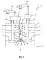
- FIGS 1 - 6 show a part of a piston engine 1, more specifically the upper part of its cylinder.
- the piston engine 1 comprises an engine block with a plurality of cylinders 3.
- the engine 1 is an Otto-cycle engine, i.e. a mixture of fuel and combustion air is ignited by a spark plug.
- the fuel used in the engine is gas, for instance natural gas.
- the engine 1 also comprises a cylinder head 2, which together with a piston and a cylinder liner defines a combustion chamber 5 of the cylinder.
- the cylinder head 2 is provided with an inlet port 6 which opens into the combustion chamber 5, through which inlet port the mixture of fuel and air is led into the combustion chamber 5.
- the fuel is mixed with combustion air in the inlet port 6.
- the flow of the mixture of fuel and combustion air from the inlet port 6 into the combustion chamber 5 is controlled by an inlet valve 7.
- the cylinder head 2 is also provided with an exhaust port 8 opening into the combustion chamber 5, through which exhaust port the exhaust gases formed during the combustion are discharged from the combustion chamber 5.
- the exhaust gas flow from the combustion chamber 5 to the exhaust port 8 is controlled by an exhaust valve 9.
- An actuating arrangement is provided in conjunction with both the inlet valve 7 and the exhaust valve 9 for moving the valves 7, 9.
- the actuating arrangement for the inlet valve comprises a yoke 13 and a rocker arm 14 arranged in conjunction with the stem of the inlet valve 7, by which rocker arm the yoke 13 and thereby the inlet valve 7 is pressed downwards in order to open it.
- the actuating arrangement for the exhaust valve comprises a yoke 13' and a rocker arm 14' arranged in conjunction with the stem of the exhaust valve 9, by which rocker arm the yoke 13' and thereby the exhaust valve 9 is pressed downwards in order to open it.
- rocker arm 14, 14' The movement of the rocker arm 14, 14' is provided by means of the cam on the camshaft, which cam is in operational connection with the rocker arm 14, 14' either directly or indirectly via a push rod.
- a spring 10 is adapted around the stem 11, 12 of the valve 7, 9, the spring force of which spring urges the valve toward the closed position according to Figure 1 , in which a valve disc 11', 12' is placed against the valve seat surface on the cylinder head 2.
- a prechamber arrangement 15 is adapted in conjunction with the upper part of a cylinder, i.e. the cylinder head 2.
- the prechamber arrangement 15 comprises a body 16 enclosing a prechamber 17, which is in flow connection with the combustion chamber 5 via nozzle holes 18.
- the prechamber arrangement 15 comprises a prechamber valve 19, by which the feeding of the mixture of fuel and combustion air from the fuel chamber 25 inside the body to the prechamber 17 is controlled.
- the prechamber arrangement 15 comprises a spark plug 20, by which the mixture of fuel and air in the prechamber 17 is ignited.
- the prechamber arrangement is placed inside the body 16, whereby it can be installed in conjunction with the cylinder head 2 as one unit.
- the prechamber valve 19 comprises an elongated valve body 21, the first end of which is provided with a valve disc 22 and the second end with a piston 23.
- the piston 23 is placed within a cylindrical chamber 28.
- the piston 23 comprises a piston surface 32 delimiting the chamber 28.
- the valve body 21 is surrounded by a spring 24, which is arranged in the chamber 28 between the piston 23 and the body 16, whereby the spring forces the prechamber valve 19 toward the closed position in which the valve disc 22 is against the seat surface on the body 16.
- the prechamber valve is in the closed position, the flow of the mixture of fuel and combustion air from the fuel chamber 25 to the prechamber 17 is prevented.
- the prechamber valve 19 is open, whereby the mixture of fuel and combustion air is allowed to flow from the fuel chamber 25 to the prechamber 17.
- the chamber 28 is in flow connection via a connecting duct 26 to a second chamber 27, which encloses a second piston 29.
- the movable second piston 29 is provided with a second piston surface 31 which delimits partially the second chamber 27.
- Both the chamber 28 and the second chamber 27 are filled with pressure medium, preferably with lubrication oil of the engine.
- the area of the second piston surface 31 is larger than that of the piston surface 32.
- the yoke 13 in conjunction with the inlet valve 7 is also in operational connection with the second piston 29 so that the yoke 13 presses simultaneously both the inlet valve 7 and the second piston 29.
- the movement of both the prechamber valve 19 and the inlet valve 7 is provided by the same arrangement, i.e. by the actuating arrangement of the inlet valve.
- the timing of the inlet valve 7 is different from that of the prechamber valve 19, i.e. their opening and closing times differ from one another. Since the areas of the piston surfaces 32, 31 delimiting the chamber 28 and the second chamber 27, respectively, are of different sizes, the movement speed and lift of the prechamber valve 19 and those of the inlet valve 7 differ from one another.
- inlet valve 7 and the second piston 29 are pressed downwards by means of the actuating arrangement of the inlet valve, i.e. by the yoke 13 and the rocker arm 14.
- the inlet valve 7 opens and the orifice of the duct 30 in the side wall of the second chamber 27 is still open.
- the second piston 29 projects into the second chamber 27 and pressure medium flows along the duct 30 into the oil space 34. Consequently, the total volume of the chamber 23 and the second chamber 27 decreases.
- the prechamber valve 19 remains in the closed position, i.e. the valve disk 22 is against the valve seat surface.
- the movement, i.e. the lift, of the prechamber valve 19 as a function of time is smaller than the lift of the inlet valve 7, as indicated in Figure 7 .
- the lift of the prechamber valve 19 relative to the lift of the inlet valve 7 can be changed by changing the ratio between the piston surface 32 of the piston and the piston surface 31 of the second piston.
- the moments when the prechamber valve 19 starts to open and closes completely may be changed by changing the closing and opening moments of the orifice of the duct 30 in the side wall of the second chamber 27, i.e. by changing for instance the position of the orifice of the duct 30 in the direction of motion of the second piston 29, i.e. in the vertical direction.
Landscapes
- Engineering & Computer Science (AREA)
- Mechanical Engineering (AREA)
- General Engineering & Computer Science (AREA)
- Chemical & Material Sciences (AREA)
- Combustion & Propulsion (AREA)
- Combustion Methods Of Internal-Combustion Engines (AREA)
- Output Control And Ontrol Of Special Type Engine (AREA)
Claims (6)
- Moteur à pistons (1) comprenant au moins un cylindre (3), un port d'entrée (6) doté d'une soupape d'entrée (7) pour transporter de l'air de combustion dans une chambre de combustion (5) du cylindre, et un agencement d'actionnement (13, 14) pour ouvrir la soupape d'entrée (7), l'agencement d'actionnement comprenant une fourche (13) et un culbuteur (14) agencés en liaison avec la tige de la soupape d'entrée (7), par lequel culbuteur (14), la fourche (13) et par conséquent la soupape d'entrée (7), est appuyée vers une position ouverte,
un agencement de préchambre adapté dans la partie supérieure (2) du cylindre, l'agencement de préchambre comprenant une préchambre (17), une soupape de préchambre contrainte par ressort (19) dotée d'une surface de piston (32) pour alimenter un mélange d'air de combustion et de carburant dans la préchambre (17), et un moyen d'allumage (20) pour allumer le mélange d'air de combustion et de carburant dans la préchambre (17), laquelle soupape de préchambre (19) peut être déplacée entre une position ouverte et une position fermée et est appuyée vers la position fermée par un ressort (24), l'agencement de préchambre (15) comprenant une chambre (28) pour du fluide de pression et une seconde chambre (27) pour du fluide de pression en connexion fluidique avec la chambre (28), laquelle chambre (28) est délimitée par la surface de piston (32) de la soupape de préchambre sur laquelle surface de piston, la pression du fluide de pression agit pour déplacer la soupape de préchambre (19) vers la position ouverte, et laquelle seconde chambre (27) est délimitée par la surface de piston (31) d'un second piston mobile (29), caractérisé en ce que l'agencement de préchambre comprend une conduite (30) pour transporter du fluide de pression vers la seconde chambre (27) et pour le décharger de la seconde chambre (27), laquelle conduite (30) est agencée pour se fermer et s'ouvrir selon la position du second piston (29), et en ce que la fourche (13) et le culbuteur (14) de la soupape d'entrée sont agencés pour déplacer le second piston (29). - Moteur à pistons selon la revendication 1, caractérisé en ce que l'aire de la surface de piston (32) de la soupape de préchambre est supérieure à l'aire de la surface de piston (31) du second piston (29).
- Moteur à pistons selon la revendication 1, caractérisé en ce que l'orifice de la conduite (30) est agencé dans la paroi latérale de la seconde chambre (27).
- Moteur selon l'une quelconque des revendications précédentes, caractérisé en ce que la chambre (28) et la seconde chambre (27) sont adaptées à l'intérieur d'un corps (16) et que le second piston (29) peut être déplacé de l'extérieur du corps (16).
- Moteur à pistons selon la revendication 1 ou 3, caractérisé en ce qu'une conduite (30) est en connexion fluidique avec le système d'huile lubrifiante du moteur.
- Moteur selon l'une quelconque des revendications précédentes, caractérisé en ce que la fourche (13) est en connexion opérationnelle avec le second piston (29), de façon à ce que la fourche (13) appuie simultanément à la fois la soupape d'entrée (7) et le second piston (29).
Applications Claiming Priority (2)
| Application Number | Priority Date | Filing Date | Title |
|---|---|---|---|
| FI20075002A FI121895B (fi) | 2007-01-03 | 2007-01-03 | Mäntämoottori |
| PCT/FI2008/050001 WO2008081083A1 (fr) | 2007-01-03 | 2008-01-02 | Unité de préchambre de moteur à pistons |
Publications (2)
| Publication Number | Publication Date |
|---|---|
| EP2097629A1 EP2097629A1 (fr) | 2009-09-09 |
| EP2097629B1 true EP2097629B1 (fr) | 2012-09-26 |
Family
ID=37745695
Family Applications (1)
| Application Number | Title | Priority Date | Filing Date |
|---|---|---|---|
| EP08701701A Active EP2097629B1 (fr) | 2007-01-03 | 2008-01-02 | Unité de préchambre de moteur à pistons |
Country Status (6)
| Country | Link |
|---|---|
| EP (1) | EP2097629B1 (fr) |
| KR (1) | KR101386364B1 (fr) |
| CN (1) | CN101583782B (fr) |
| ES (1) | ES2394534T3 (fr) |
| FI (1) | FI121895B (fr) |
| WO (1) | WO2008081083A1 (fr) |
Cited By (5)
| Publication number | Priority date | Publication date | Assignee | Title |
|---|---|---|---|---|
| WO2015124829A1 (fr) | 2014-02-21 | 2015-08-27 | Wärtsilä Finland Oy | Agencement de préchambre |
| WO2016075361A1 (fr) | 2014-11-12 | 2016-05-19 | Wärtsilä Finland Oy | Moteur à gaz à combustion interne à combustion pauvre comportant un dispositif d'allumage à plasma à décharge à barrière diélectrique à l'intérieur d'une pré-chambre de combustion |
| WO2016075357A1 (fr) | 2014-11-12 | 2016-05-19 | Wärtsilä Finland Oy | Ensemble d'allumage et procédé d'allumage d'un mélange de combustible dans une chambre de combustion d'un moteur à combustion interne à piston |
| WO2016075358A1 (fr) | 2014-11-12 | 2016-05-19 | Wärtsilä Finland Oy | Ensemble chambre de précombustion adaptable dans une culasse d'un moteur à combustion interne, et culasse |
| WO2017093598A1 (fr) | 2015-12-04 | 2017-06-08 | Wärtsilä Finland Oy | Ensemble d'allumage à plasma par micro-ondes |
Families Citing this family (11)
| Publication number | Priority date | Publication date | Assignee | Title |
|---|---|---|---|---|
| KR101359149B1 (ko) * | 2009-11-13 | 2014-02-05 | 현대중공업 주식회사 | 가스엔진용 프리챔버 |
| DE102009054055A1 (de) | 2009-11-20 | 2011-05-26 | Schaeffler Technologies Gmbh & Co. Kg | Schaltbare Vorrichtung zur Druckversorgung |
| KR101926861B1 (ko) | 2012-02-29 | 2019-03-08 | 현대자동차주식회사 | 프리챔버 제트점화기 및 이를 적용한 연소실을 갖춘 엔진 |
| US10087817B2 (en) | 2014-01-21 | 2018-10-02 | Peter Kreuter | Reciprocating piston internal combustion engine having an ancillary chamber containing a piston, and method for operating the same |
| AT516621B1 (de) | 2015-02-27 | 2016-07-15 | Ge Jenbacher Gmbh & Co Og | Vorkammergasventil |
| AT516717B1 (de) | 2015-05-26 | 2016-08-15 | Ge Jenbacher Gmbh & Co Og | Brennkraftmaschine |
| CN108779702A (zh) * | 2015-10-08 | 2018-11-09 | 康明斯公司 | 预燃室组件 |
| US20160069251A1 (en) * | 2015-11-13 | 2016-03-10 | Caterpillar Inc. | Pressure-limiting device for pre-combustion chamber |
| JP2018172973A (ja) * | 2017-03-31 | 2018-11-08 | 本田技研工業株式会社 | 副室式内燃機関の動弁機構 |
| CN113027595A (zh) * | 2021-04-29 | 2021-06-25 | 林永男 | 具有组合燃烧室的活塞发动机及其工作方法 |
| CN117846768A (zh) * | 2023-11-14 | 2024-04-09 | 中国船舶集团有限公司第七一一研究所 | 内燃机、船舶及发电设备 |
Family Cites Families (7)
| Publication number | Priority date | Publication date | Assignee | Title |
|---|---|---|---|---|
| JPS543B2 (fr) * | 1974-02-28 | 1979-01-05 | ||
| JPS5119214A (fr) * | 1974-08-09 | 1976-02-16 | Nissan Motor | |
| GB1471415A (en) * | 1974-12-03 | 1977-04-27 | British Leyland Uk Ltd | Spark ignition internal combustion engine |
| US3987769A (en) * | 1975-03-31 | 1976-10-26 | General Motors Corporation | Jet ignition engine with valve-carried ignition chamber |
| EP0480545A3 (en) * | 1988-12-29 | 1992-07-01 | Yanmar Diesel Engine Co. Ltd. | Gas engine |
| US5560326A (en) * | 1993-06-26 | 1996-10-01 | Coventry University | Internal combustion engine |
| US6003487A (en) * | 1995-08-05 | 1999-12-21 | Merritt; Dan | Internal combustion engine |
-
2007
- 2007-01-03 FI FI20075002A patent/FI121895B/fi not_active IP Right Cessation
-
2008
- 2008-01-02 EP EP08701701A patent/EP2097629B1/fr active Active
- 2008-01-02 ES ES08701701T patent/ES2394534T3/es active Active
- 2008-01-02 KR KR1020097016181A patent/KR101386364B1/ko active Active
- 2008-01-02 CN CN2008800017081A patent/CN101583782B/zh active Active
- 2008-01-02 WO PCT/FI2008/050001 patent/WO2008081083A1/fr not_active Ceased
Cited By (5)
| Publication number | Priority date | Publication date | Assignee | Title |
|---|---|---|---|---|
| WO2015124829A1 (fr) | 2014-02-21 | 2015-08-27 | Wärtsilä Finland Oy | Agencement de préchambre |
| WO2016075361A1 (fr) | 2014-11-12 | 2016-05-19 | Wärtsilä Finland Oy | Moteur à gaz à combustion interne à combustion pauvre comportant un dispositif d'allumage à plasma à décharge à barrière diélectrique à l'intérieur d'une pré-chambre de combustion |
| WO2016075357A1 (fr) | 2014-11-12 | 2016-05-19 | Wärtsilä Finland Oy | Ensemble d'allumage et procédé d'allumage d'un mélange de combustible dans une chambre de combustion d'un moteur à combustion interne à piston |
| WO2016075358A1 (fr) | 2014-11-12 | 2016-05-19 | Wärtsilä Finland Oy | Ensemble chambre de précombustion adaptable dans une culasse d'un moteur à combustion interne, et culasse |
| WO2017093598A1 (fr) | 2015-12-04 | 2017-06-08 | Wärtsilä Finland Oy | Ensemble d'allumage à plasma par micro-ondes |
Also Published As
| Publication number | Publication date |
|---|---|
| KR101386364B1 (ko) | 2014-04-16 |
| ES2394534T3 (es) | 2013-02-01 |
| CN101583782B (zh) | 2012-06-20 |
| FI121895B (fi) | 2011-05-31 |
| FI20075002L (fi) | 2008-07-04 |
| WO2008081083A1 (fr) | 2008-07-10 |
| EP2097629A1 (fr) | 2009-09-09 |
| KR20090107048A (ko) | 2009-10-12 |
| CN101583782A (zh) | 2009-11-18 |
| FI20075002A0 (fi) | 2007-01-03 |
Similar Documents
| Publication | Publication Date | Title |
|---|---|---|
| EP2097629A1 (fr) | Unité de préchambre de moteur à pistons | |
| US7819100B2 (en) | Internal combustion engine with intake valves having a variable actuation and a lift profile including a constant lift boot portion | |
| US5454356A (en) | Engine with pre-chamber | |
| US6895912B2 (en) | Variable valve control apparatus for engine and method thereof | |
| JP2008202545A (ja) | デュアルフュールエンジン | |
| CZ281119B6 (cs) | Spalovací motor | |
| US7395813B2 (en) | Method of controlling the intake and/or the exhaust of at least one deactivated cylinder of an internal-combustion engine | |
| EP1484498B1 (fr) | Moteur a combustion interne a injection du carburant dans le cylindre | |
| US5178109A (en) | Heat-insulating engine with swirl chambers | |
| US20120325167A1 (en) | Valve drive system of internal combustion engine | |
| US9279350B2 (en) | Intake valve closure control for dual-fuel engines | |
| JP3695019B2 (ja) | 副室容積可変式ガスエンジン | |
| EP3111060B1 (fr) | Agencement de préchambre | |
| JP2009180220A (ja) | 高圧酸素噴射式内燃機関 | |
| CN109915252B (zh) | 中冷绝热内燃机 | |
| JP2009275545A (ja) | 内燃機関の可変動弁装置 | |
| KR101305821B1 (ko) | 가변 압축비 엔진 | |
| US5070834A (en) | Diesel engine with a precombustion chamber | |
| JP4341166B2 (ja) | 予混合圧縮着火燃焼エンジン | |
| WO1997002417A1 (fr) | Dispositif dans une culasse de cylindre | |
| JP2011236789A (ja) | 燃料供給装置 | |
| CA2471588C (fr) | Soupape | |
| CN113167142A (zh) | 改进的内燃机 | |
| RU2206770C1 (ru) | Устройство для регулирования объема камеры сгорания и мощности двигателя внутреннего сгорания | |
| US20050098138A1 (en) | Diesel four cycle, 1 poppet valve, modified head, piston and valves |
Legal Events
| Date | Code | Title | Description |
|---|---|---|---|
| PUAI | Public reference made under article 153(3) epc to a published international application that has entered the european phase |
Free format text: ORIGINAL CODE: 0009012 |
|
| 17P | Request for examination filed |
Effective date: 20090610 |
|
| AK | Designated contracting states |
Kind code of ref document: A1 Designated state(s): AT BE BG CH CY CZ DE DK EE ES FI FR GB GR HR HU IE IS IT LI LT LU LV MC MT NL NO PL PT RO SE SI SK TR |
|
| 17Q | First examination report despatched |
Effective date: 20091202 |
|
| DAX | Request for extension of the european patent (deleted) | ||
| GRAP | Despatch of communication of intention to grant a patent |
Free format text: ORIGINAL CODE: EPIDOSNIGR1 |
|
| GRAS | Grant fee paid |
Free format text: ORIGINAL CODE: EPIDOSNIGR3 |
|
| GRAA | (expected) grant |
Free format text: ORIGINAL CODE: 0009210 |
|
| AK | Designated contracting states |
Kind code of ref document: B1 Designated state(s): AT BE BG CH CY CZ DE DK EE ES FI FR GB GR HR HU IE IS IT LI LT LU LV MC MT NL NO PL PT RO SE SI SK TR |
|
| REG | Reference to a national code |
Ref country code: GB Ref legal event code: FG4D |
|
| REG | Reference to a national code |
Ref country code: CH Ref legal event code: EP |
|
| REG | Reference to a national code |
Ref country code: AT Ref legal event code: REF Ref document number: 577169 Country of ref document: AT Kind code of ref document: T Effective date: 20121015 |
|
| REG | Reference to a national code |
Ref country code: IE Ref legal event code: FG4D |
|
| REG | Reference to a national code |
Ref country code: DE Ref legal event code: R096 Ref document number: 602008018979 Country of ref document: DE Effective date: 20121122 |
|
| PG25 | Lapsed in a contracting state [announced via postgrant information from national office to epo] |
Ref country code: FI Free format text: LAPSE BECAUSE OF FAILURE TO SUBMIT A TRANSLATION OF THE DESCRIPTION OR TO PAY THE FEE WITHIN THE PRESCRIBED TIME-LIMIT Effective date: 20120926 Ref country code: LT Free format text: LAPSE BECAUSE OF FAILURE TO SUBMIT A TRANSLATION OF THE DESCRIPTION OR TO PAY THE FEE WITHIN THE PRESCRIBED TIME-LIMIT Effective date: 20120926 Ref country code: NO Free format text: LAPSE BECAUSE OF FAILURE TO SUBMIT A TRANSLATION OF THE DESCRIPTION OR TO PAY THE FEE WITHIN THE PRESCRIBED TIME-LIMIT Effective date: 20121226 Ref country code: HR Free format text: LAPSE BECAUSE OF FAILURE TO SUBMIT A TRANSLATION OF THE DESCRIPTION OR TO PAY THE FEE WITHIN THE PRESCRIBED TIME-LIMIT Effective date: 20120926 |
|
| REG | Reference to a national code |
Ref country code: ES Ref legal event code: FG2A Ref document number: 2394534 Country of ref document: ES Kind code of ref document: T3 Effective date: 20130201 |
|
| REG | Reference to a national code |
Ref country code: NO Ref legal event code: T2 Effective date: 20120926 |
|
| REG | Reference to a national code |
Ref country code: LT Ref legal event code: MG4D Effective date: 20120926 |
|
| REG | Reference to a national code |
Ref country code: NL Ref legal event code: VDEP Effective date: 20120926 |
|
| PG25 | Lapsed in a contracting state [announced via postgrant information from national office to epo] |
Ref country code: SI Free format text: LAPSE BECAUSE OF FAILURE TO SUBMIT A TRANSLATION OF THE DESCRIPTION OR TO PAY THE FEE WITHIN THE PRESCRIBED TIME-LIMIT Effective date: 20120926 Ref country code: LV Free format text: LAPSE BECAUSE OF FAILURE TO SUBMIT A TRANSLATION OF THE DESCRIPTION OR TO PAY THE FEE WITHIN THE PRESCRIBED TIME-LIMIT Effective date: 20120926 Ref country code: GR Free format text: LAPSE BECAUSE OF FAILURE TO SUBMIT A TRANSLATION OF THE DESCRIPTION OR TO PAY THE FEE WITHIN THE PRESCRIBED TIME-LIMIT Effective date: 20121227 Ref country code: SE Free format text: LAPSE BECAUSE OF FAILURE TO SUBMIT A TRANSLATION OF THE DESCRIPTION OR TO PAY THE FEE WITHIN THE PRESCRIBED TIME-LIMIT Effective date: 20120926 |
|
| PG25 | Lapsed in a contracting state [announced via postgrant information from national office to epo] |
Ref country code: IS Free format text: LAPSE BECAUSE OF FAILURE TO SUBMIT A TRANSLATION OF THE DESCRIPTION OR TO PAY THE FEE WITHIN THE PRESCRIBED TIME-LIMIT Effective date: 20130126 Ref country code: BE Free format text: LAPSE BECAUSE OF FAILURE TO SUBMIT A TRANSLATION OF THE DESCRIPTION OR TO PAY THE FEE WITHIN THE PRESCRIBED TIME-LIMIT Effective date: 20120926 Ref country code: NL Free format text: LAPSE BECAUSE OF FAILURE TO SUBMIT A TRANSLATION OF THE DESCRIPTION OR TO PAY THE FEE WITHIN THE PRESCRIBED TIME-LIMIT Effective date: 20120926 Ref country code: CZ Free format text: LAPSE BECAUSE OF FAILURE TO SUBMIT A TRANSLATION OF THE DESCRIPTION OR TO PAY THE FEE WITHIN THE PRESCRIBED TIME-LIMIT Effective date: 20120926 Ref country code: RO Free format text: LAPSE BECAUSE OF FAILURE TO SUBMIT A TRANSLATION OF THE DESCRIPTION OR TO PAY THE FEE WITHIN THE PRESCRIBED TIME-LIMIT Effective date: 20120926 Ref country code: EE Free format text: LAPSE BECAUSE OF FAILURE TO SUBMIT A TRANSLATION OF THE DESCRIPTION OR TO PAY THE FEE WITHIN THE PRESCRIBED TIME-LIMIT Effective date: 20120926 |
|
| PG25 | Lapsed in a contracting state [announced via postgrant information from national office to epo] |
Ref country code: SK Free format text: LAPSE BECAUSE OF FAILURE TO SUBMIT A TRANSLATION OF THE DESCRIPTION OR TO PAY THE FEE WITHIN THE PRESCRIBED TIME-LIMIT Effective date: 20120926 Ref country code: PT Free format text: LAPSE BECAUSE OF FAILURE TO SUBMIT A TRANSLATION OF THE DESCRIPTION OR TO PAY THE FEE WITHIN THE PRESCRIBED TIME-LIMIT Effective date: 20130128 Ref country code: PL Free format text: LAPSE BECAUSE OF FAILURE TO SUBMIT A TRANSLATION OF THE DESCRIPTION OR TO PAY THE FEE WITHIN THE PRESCRIBED TIME-LIMIT Effective date: 20120926 Ref country code: CY Free format text: LAPSE BECAUSE OF FAILURE TO SUBMIT A TRANSLATION OF THE DESCRIPTION OR TO PAY THE FEE WITHIN THE PRESCRIBED TIME-LIMIT Effective date: 20120926 |
|
| PG25 | Lapsed in a contracting state [announced via postgrant information from national office to epo] |
Ref country code: BG Free format text: LAPSE BECAUSE OF FAILURE TO SUBMIT A TRANSLATION OF THE DESCRIPTION OR TO PAY THE FEE WITHIN THE PRESCRIBED TIME-LIMIT Effective date: 20121226 Ref country code: DK Free format text: LAPSE BECAUSE OF FAILURE TO SUBMIT A TRANSLATION OF THE DESCRIPTION OR TO PAY THE FEE WITHIN THE PRESCRIBED TIME-LIMIT Effective date: 20120926 |
|
| PLBE | No opposition filed within time limit |
Free format text: ORIGINAL CODE: 0009261 |
|
| STAA | Information on the status of an ep patent application or granted ep patent |
Free format text: STATUS: NO OPPOSITION FILED WITHIN TIME LIMIT |
|
| PG25 | Lapsed in a contracting state [announced via postgrant information from national office to epo] |
Ref country code: MC Free format text: LAPSE BECAUSE OF NON-PAYMENT OF DUE FEES Effective date: 20130131 |
|
| REG | Reference to a national code |
Ref country code: CH Ref legal event code: PL |
|
| 26N | No opposition filed |
Effective date: 20130627 |
|
| REG | Reference to a national code |
Ref country code: IE Ref legal event code: MM4A |
|
| REG | Reference to a national code |
Ref country code: DE Ref legal event code: R097 Ref document number: 602008018979 Country of ref document: DE Effective date: 20130627 |
|
| REG | Reference to a national code |
Ref country code: FR Ref legal event code: ST Effective date: 20130930 |
|
| PG25 | Lapsed in a contracting state [announced via postgrant information from national office to epo] |
Ref country code: LI Free format text: LAPSE BECAUSE OF NON-PAYMENT OF DUE FEES Effective date: 20130131 Ref country code: CH Free format text: LAPSE BECAUSE OF NON-PAYMENT OF DUE FEES Effective date: 20130131 |
|
| PG25 | Lapsed in a contracting state [announced via postgrant information from national office to epo] |
Ref country code: FR Free format text: LAPSE BECAUSE OF NON-PAYMENT OF DUE FEES Effective date: 20130131 |
|
| PG25 | Lapsed in a contracting state [announced via postgrant information from national office to epo] |
Ref country code: IE Free format text: LAPSE BECAUSE OF NON-PAYMENT OF DUE FEES Effective date: 20130102 |
|
| PG25 | Lapsed in a contracting state [announced via postgrant information from national office to epo] |
Ref country code: MT Free format text: LAPSE BECAUSE OF FAILURE TO SUBMIT A TRANSLATION OF THE DESCRIPTION OR TO PAY THE FEE WITHIN THE PRESCRIBED TIME-LIMIT Effective date: 20120926 |
|
| PG25 | Lapsed in a contracting state [announced via postgrant information from national office to epo] |
Ref country code: TR Free format text: LAPSE BECAUSE OF FAILURE TO SUBMIT A TRANSLATION OF THE DESCRIPTION OR TO PAY THE FEE WITHIN THE PRESCRIBED TIME-LIMIT Effective date: 20120926 |
|
| PG25 | Lapsed in a contracting state [announced via postgrant information from national office to epo] |
Ref country code: HU Free format text: LAPSE BECAUSE OF FAILURE TO SUBMIT A TRANSLATION OF THE DESCRIPTION OR TO PAY THE FEE WITHIN THE PRESCRIBED TIME-LIMIT; INVALID AB INITIO Effective date: 20080102 Ref country code: LU Free format text: LAPSE BECAUSE OF NON-PAYMENT OF DUE FEES Effective date: 20130102 |
|
| PGFP | Annual fee paid to national office [announced via postgrant information from national office to epo] |
Ref country code: IT Payment date: 20240129 Year of fee payment: 17 |
|
| PG25 | Lapsed in a contracting state [announced via postgrant information from national office to epo] |
Ref country code: IT Free format text: LAPSE BECAUSE OF NON-PAYMENT OF DUE FEES Effective date: 20250102 |
|
| PGFP | Annual fee paid to national office [announced via postgrant information from national office to epo] |
Ref country code: GB Payment date: 20260330 Year of fee payment: 19 |
|
| PGFP | Annual fee paid to national office [announced via postgrant information from national office to epo] |
Ref country code: DE Payment date: 20260121 Year of fee payment: 19 |
|
| PGFP | Annual fee paid to national office [announced via postgrant information from national office to epo] |
Ref country code: AT Payment date: 20260122 Year of fee payment: 19 |
|
| PGFP | Annual fee paid to national office [announced via postgrant information from national office to epo] |
Ref country code: ES Payment date: 20260424 Year of fee payment: 19 |
|
| PGFP | Annual fee paid to national office [announced via postgrant information from national office to epo] |
Ref country code: NO Payment date: 20260401 Year of fee payment: 19 |