EP2097680B1 - Dispositif de cuisson - Google Patents
Dispositif de cuisson Download PDFInfo
- Publication number
- EP2097680B1 EP2097680B1 EP07857569.3A EP07857569A EP2097680B1 EP 2097680 B1 EP2097680 B1 EP 2097680B1 EP 07857569 A EP07857569 A EP 07857569A EP 2097680 B1 EP2097680 B1 EP 2097680B1
- Authority
- EP
- European Patent Office
- Prior art keywords
- cook top
- frame
- cooking device
- front panel
- extension
- Prior art date
- Legal status (The legal status is an assumption and is not a legal conclusion. Google has not performed a legal analysis and makes no representation as to the accuracy of the status listed.)
- Active
Links
- 238000010411 cooking Methods 0.000 title claims description 30
- 238000003825 pressing Methods 0.000 claims description 20
- 210000001061 forehead Anatomy 0.000 claims description 9
- 238000005452 bending Methods 0.000 claims description 5
- 210000003298 dental enamel Anatomy 0.000 description 8
- 230000002238 attenuated effect Effects 0.000 description 4
- 238000005336 cracking Methods 0.000 description 4
- 238000004519 manufacturing process Methods 0.000 description 3
- 238000000034 method Methods 0.000 description 3
- 229910000831 Steel Inorganic materials 0.000 description 2
- 238000010438 heat treatment Methods 0.000 description 2
- 239000000463 material Substances 0.000 description 2
- 239000010959 steel Substances 0.000 description 2
- 239000002320 enamel (paints) Substances 0.000 description 1
- 210000003128 head Anatomy 0.000 description 1
- 238000007493 shaping process Methods 0.000 description 1
Images


Classifications
-
- F—MECHANICAL ENGINEERING; LIGHTING; HEATING; WEAPONS; BLASTING
- F24—HEATING; RANGES; VENTILATING
- F24C—DOMESTIC STOVES OR RANGES ; DETAILS OF DOMESTIC STOVES OR RANGES, OF GENERAL APPLICATION
- F24C15/00—Details
- F24C15/10—Tops, e.g. hot plates; Rings
-
- F—MECHANICAL ENGINEERING; LIGHTING; HEATING; WEAPONS; BLASTING
- F24—HEATING; RANGES; VENTILATING
- F24C—DOMESTIC STOVES OR RANGES ; DETAILS OF DOMESTIC STOVES OR RANGES, OF GENERAL APPLICATION
- F24C15/00—Details
- F24C15/08—Foundations or supports plates; Legs or pillars; Casings; Wheels
Definitions
- the present invention relates to a cooking device to which the cook top is mounted whereon cooking processes are performed.
- the cook top disposed on the top surface of cooking devices including burners thereon for performing the cooking process is produced of steel sheet and coated with enamel.
- the enamel coated cook top is being mounted on the frame, it can be subjected to tensions and impacts and this may result in damaging the enamel, which is a fragile material.
- connection springs are used to resiliently mount the cook top on the frame; however, enamel cracking cannot be avoided while mounting the cook top particularly on the frame.
- German Patent Document No DE19613320 a work surface fixing system used in household appliances is explained.
- the fixing system comprises a pair of spring sockets at opposite ends of the switch panel extending across the top front edge of the household appliance.
- the aim of the present invention is to the realization of a cooking device wherein the cook top can be mounted easily.
- the cook top is mounted by pressing down on the connection springs that are previously fastened to the upper surface of the frame which forms the skeleton of the body or to the front panel.
- the connection springs By means of the connection springs, the impacts that may affect the cook top during assembly or use are attenuated and thus the enamel coated on the cook top is prevented from cracking.
- connection spring comprises a fixing extension for assembling thereof to the frame and a resilient extension for attenuating the impacts by leaning on the bent side of the cook top, shaped as an inverted V, one arm of the V shape connected to the fixing extension and the other aim bearing on the front or lateral side of the cook top.
- the resilient extension comprises a continuous forehead surface that stretches the cook top backwards by the bent sides of the cook top pushing while the cook top is mounted by pressing downwards and a pressing extension that curves inwards by bending the forehead surface concavely that compresses the cook top by leaning on the side of the cook top seated on the frame or the front panel.
- a supporting protrusion is provided on the frame or the front panel that restricts the forwards, backwards motion of the connection spring and the connection spring is assembled by being seated on the supporting protrusion by means of a depression disposed on the fixing extension.
- a channel is arranged on the fixing extension and the connection spring is assembled on the frame allowing thereof to slide along the channel.
- a resilient extension is situated on the rear side of the connection spring and this extension increases stretching of the spring by leaning on a supporting protrusion arranged at the rear.
- stoppers are provided on the cook top that prevent the sideways movement of the cook top by leaning on the connection springs.
- the front side of the cook top is in the curved form and the connection springs are positioned angularly with respect to each other and in the vertical direction to the curved front side of the cook top such that the cook top is mounted on the frame by pressing down thereon.
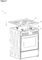
- the cooking device (1) comprises a body wherein the cooking process is performed on the upper surface and/or the interior volume, a front panel (2) including the elements such as knobs and displays thereon, a cook top (3) mounted on the body, containing the gas burners and/or electrical heating plates for heating and/or cooking and a frame (4) to which the walls forming the body, the front panel (2) and the cook top (3) are fastened ( Figures 1 , 2 ).
- the cook top (3) is produced by shaping the steel sheet material and coated with enamel.
- the cook top (3) comprises at least one side (12) formed by bending downwards the portions corresponding to above the front panel (2) and the frame (4) ( Figures 1 , 2 , 3 , 5 ).
- the cooking device (1) furthermore comprises a connection spring (5) that provides attaching the cook top (3), which is mounted to the frame, to the frame (4) to be resiliently and attenuating the forces acting on the cook top (3).
- the resilient extension (7) comprises an continuous forehead surface (A) disposed on the front side thereof over which the side (12) slides and pushes backwards while the cook top (3) is mounted by pressing down and a pressing extension (B) that curves inwardly by bending the forehead surface (A) concavely which compresses the cook top (3) by leaning on the inside of the side (12) seated on the frame (4) ( Figure 4 ).
- the continuous form of the forehead surface (A) provides the stretching of the resilient extension (7).
- connection spring (5) is fixed to the front panel (2) or the frame (4) by means of the fixing extension (6).
- the cook top (3) is brought over the frame (4) and after the burner head openings on the cook top (3) are aligned with the burners, the cook top (3) is lowered to be seated on the frame (4) ( Figures 1 , 2 ).
- the rear side of the cook top (3) is fixed by fastening elements such as screws or the like.
- the front and lateral sides (12) of the cook top (3) are bent downwards.
- the front or the lateral side (12) slides on the forehead surface (A) of the resilient extension (7) in front of the connection spring (5) and stretches the resilient extension (7) backwards and after passing beyond the forehead surface (A) goes under the pressing extension (B). Assembling is completed by compressing the side (12) between the pressing extension (B) and the frame (4) or the upper surface of the front panel (2).
- the resilient extension (7) does not stretch easily since the spring constant is high, only stretches under excessive forces, preventing cracking of the enamel coating of the cook top (3).
- the cooking device (1) comprises a supporting protrusion (8) disposed on the frame (4) or the front panel (2) that restricts the forwards, backwards motion of the connection spring (5) ( Figure 5 ).
- the motion of the connection spring (5) in the forwards, backwards directions is restricted by fixing on the supporting protrusion (8) or by bearing on the supporting protrusion (8), the movement of the cook top (3) in the forwards, backwards directions is attenuated only by the stretching of the resilient extension (7).
- connection spring (5) comprises a depression (9) for assembling thereof by being seated on the supporting protrusion (8), disposed on the fixing extension (6) and formed preferably by bending the fixing extension (6) ( Figures 4, 5 ).
- connection spring (5) comprises a channel (10) arranged on the fixing extension (6) for assembling thereof on the frame (4) by allowing to slide along a certain distance ( Figure 6 ).
- the connection spring (5) is attached to the frame (4) or the front panel (2) by a fastening element such as a screw, pin etc. that can move inside the channel (10) formed on the fixing extension (6) and attenuates the movement of the cook top (3) in the forwards, backwards directions by means of the channel (10) and also by the stretching feature of the resilient extension (7).
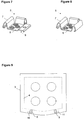
- the cooking device (1) comprises one or more stoppers (11) situated on the cook top (3) that prevent the sideways movement of the cook top (3) by contacting to the connection spring (5) from the side ( Figure 9 ).
- the cooking device (1) comprises a cook top (3), the front side configured to be curved that is mounted on connection springs (5) by pressing down and connection springs (5) fixed on the frame (4) or the front panel (2), positioned angularly with respect to each other and in the vertical direction to the curved front side of the cook top (3) such that the cook top (3) is mounted on the frame (4) by pressing downwards ( Figure 9 ).
- connection spring (5) furthermore comprises additional resilient elements that extend along the rear and lateral sides thereof that increase the attenuation of impacts acting on the cook top (3) ( Figures 7, 8 ).
- additional resilient elements that extend along the rear and lateral sides thereof that increase the attenuation of impacts acting on the cook top (3) ( Figures 7, 8 ).
- the movement of the cook top (3) both in the forwards, backwards and right and left directions is attenuated by means of the additional resilient elements.
- the enamel coated cook top (3) is mounted on the frame (4) or the front panel (2), the impacts acting thereon are attenuated by means of the connection springs (5) and cracking hence damaging of the enamel is prevented.
- the front side curved cook top (3) is mounted easily by pressing down and fitting to the connection springs (5), moreover since the cook top (3) is mounted from the top by aligning the burner openings thereon with the burners, the cook top (3) is prevented from bumping to the burners and being damaged during assembling.
Landscapes
- Engineering & Computer Science (AREA)
- Chemical & Material Sciences (AREA)
- Combustion & Propulsion (AREA)
- Mechanical Engineering (AREA)
- General Engineering & Computer Science (AREA)
- Combinations Of Kitchen Furniture (AREA)
- Baking, Grill, Roasting (AREA)
- Electric Stoves And Ranges (AREA)
Claims (7)
- Un dispositif de cuisson (1) comprenant des parois, qui forment un corps, un panneau avant (2) contenant des éléments particulièrement des boutons rotatifs et des dispositifs d'affichage, une table de cuisson (3) qui est montée sur le corps et qui présente au moins un côté (12) plié vers le bas, et un cadre (4) auquel les parois, le panneau avant (2) et la table de cuisson (3) sont fixés, et l'au moins un côté (12) plié vers le bas, ayant une partie placée sur le panneau avant (2) et/ou le cadre (4), caractérisé en ce que le dispositif de cuisson comprend en outre un ressort de connexion (5)- utilisé pour fixer la table de cuisson (3) sur le cadre (4) en appuyant vers le bas,- qui présente une extension de fixation (6) pour monter sur le cadre (4) ou le panneau avant (2) et- une extension élastique (7) en forme d'un V inversé, un bras de la structure en V relié à une extrémité de l'extension de fixation (6) et l'autre bras s'appuyant sur ladite partie du côté (12) placée au-dessus du panneau avant (2) et/ou du cadre (4), de telle sorte qu'elle est étirée vers l'arrière par l'au moins un côté (12) de la table de cuisson (3) tandis la table de cuisson (3) est montée en appuyant vers le bas, et de telle sorte qu'elle retourne à sa position précédente lorsque la table de cuisson (3) est correctement placée sur le cadre (4), donc exerçant une force sur le côté (12) à partir de l'intérieur.
- Un dispositif de cuisson (1) selon la Revendication 1, caractérisé par le ressort de connexion (5) comprenant l'extension élastique (7) qui présente une surface de front continue (A) arrangée sur le côté avant de celle-ci sur laquelle l'au moins un côté (12) glisse et pousse vers l'arrière tandis que la table de cuisson (3) est montée en appuyant vers le bas et une extension de pression (B) qui se courbe vers l'intérieur en pliant la surface de front (A) de manière concave, qui comprime la table de cuisson (3) en s'appuyant sur l'intérieur de l'au moins un côté (12) placé sur le cadre (4).
- Un dispositif de cuisson (1) selon la Revendication 1, caractérisé par une protubérance de support (8) qui est disposée sur le cadre (4) ou sur le panneau avant (2) et qui limite le mouvement du ressort de connexion (5) dans les directions vers l'avant et vers l'arrière.
- Un dispositif de cuisson (1) selon la Revendication 3, caractérisé par le ressort de connexion (5) comprenant une dépression (9) qui est arrangée sur l'extension de fixation (6) pour l'assemblage de celle-ci en étant placée sur la protubérance de support (8).
- Un dispositif de cuisson (1) selon la Revendication 1, caractérisé par le ressort de connexion (5) comprenant un canal (10) qui est arrangé sur l'extension de fixation (6) pour l'assemblage de celle-ci sur le cadre (4) en permettant son glissement le long d'une certaine distance.
- Un dispositif de cuisson (1) selon l'une quelconque des revendications précédentes, caractérisé par une ou plusieurs butées (11) qui sont arrangées sur la table de cuisson (3) et qui empêchent le mouvement latéral de la table de cuisson (3) en touchant le ressort de connexion (5) à partir du côté.
- Un dispositif de cuisson (1) selon l'une quelconque des revendications précédentes, caractérisé par la table de cuisson (3) dont le côté avant est courbé, qui est montée sur les ressorts de connexion (5) en appuyant sur le bas, et les ressorts de connexion (5) qui sont fixés sur le cadre (4) ou sur le panneau avant (2), positionnés angulairement par rapport l'un à l'autre dans la direction verticale au côté avant courbé de la table de cuisson (3) de telle sorte que la table de cuisson (3) est montée sur le cadre (4) en appuyant vers le bas.
Priority Applications (1)
| Application Number | Priority Date | Filing Date | Title |
|---|---|---|---|
| PL07857569T PL2097680T3 (pl) | 2006-12-28 | 2007-12-14 | Kuchenka |
Applications Claiming Priority (2)
| Application Number | Priority Date | Filing Date | Title |
|---|---|---|---|
| TR200607581 | 2006-12-28 | ||
| PCT/EP2007/063922 WO2008080795A2 (fr) | 2006-12-28 | 2007-12-14 | Dispositif de cuisson |
Publications (2)
| Publication Number | Publication Date |
|---|---|
| EP2097680A2 EP2097680A2 (fr) | 2009-09-09 |
| EP2097680B1 true EP2097680B1 (fr) | 2016-02-10 |
Family
ID=39589028
Family Applications (1)
| Application Number | Title | Priority Date | Filing Date |
|---|---|---|---|
| EP07857569.3A Active EP2097680B1 (fr) | 2006-12-28 | 2007-12-14 | Dispositif de cuisson |
Country Status (4)
| Country | Link |
|---|---|
| EP (1) | EP2097680B1 (fr) |
| ES (1) | ES2568684T3 (fr) |
| PL (1) | PL2097680T3 (fr) |
| WO (1) | WO2008080795A2 (fr) |
Cited By (3)
| Publication number | Priority date | Publication date | Assignee | Title |
|---|---|---|---|---|
| WO2018063115A2 (fr) | 2016-07-22 | 2018-04-05 | Femaş Metal Sanayi̇ Ve Ti̇caret Anoni̇m Şi̇rketi̇ | Mécanisme souple pour dispositifs de cuisson |
| WO2019096488A1 (fr) | 2017-11-17 | 2019-05-23 | Arcelik Anonim Sirketi | Dispositif de cuisson avec ensemble de plaque supérieure amélioré |
| US10816217B2 (en) | 2018-01-26 | 2020-10-27 | Haier Us Appliance Solutions, Inc. | Oven appliance |
Families Citing this family (5)
| Publication number | Priority date | Publication date | Assignee | Title |
|---|---|---|---|---|
| ES2373152B1 (es) * | 2008-11-26 | 2012-12-10 | Bsh Electrodomésticos España, S.A. | Campo de cocción y procedimiento para la fabricación de un campo de cocción. |
| RU2615537C2 (ru) | 2011-12-20 | 2017-04-05 | Бсх Хаусгерете Гмбх | Кухонный прибор с пружинным элементом |
| CN105612389A (zh) * | 2013-09-18 | 2016-05-25 | 阿塞里克股份有限公司 | 包括铸铁燃烧器面板的炉灶 |
| ES2564314B1 (es) | 2014-08-20 | 2016-12-28 | Domingo Panea Medina | Cisterna de doble descarga para inodoros |
| WO2020136254A1 (fr) | 2018-12-27 | 2020-07-02 | Arcelik Anonim Sirketi | Dispositif de cuisson |
Family Cites Families (6)
| Publication number | Priority date | Publication date | Assignee | Title |
|---|---|---|---|---|
| GB430829A (en) * | 1934-01-09 | 1935-06-26 | Falk Stadelmann And Company Lt | Improvements in cooking apparatus |
| DE9108044U1 (de) * | 1991-06-29 | 1992-07-23 | Licentia Patent-Verwaltungs-Gmbh, 6000 Frankfurt | Einbaugerät, wie Glaskeramik-Kochfeld oder dergleichen |
| US5549098A (en) * | 1994-02-16 | 1996-08-27 | Maytag Corporation | Glass range top-seal system |
| DE4434821C2 (de) * | 1994-09-29 | 1997-12-11 | Schott Glaswerke | Anordnung zur Montage und Halterung eines Einbaukochfeldes |
| DE19613320C1 (de) * | 1996-04-03 | 1997-04-30 | Bauknecht Hausgeraete | Vorrichtung zum Befestigen einer Arbeitsplatte auf einer Haushaltsmaschine |
| DE102006003319B4 (de) * | 2006-01-23 | 2008-01-03 | Electrolux Home Products Corporation N.V. | Befestigungselement für die Befestigung eines Bauteils an einem Trägerelement |
-
2007
- 2007-12-14 EP EP07857569.3A patent/EP2097680B1/fr active Active
- 2007-12-14 ES ES07857569.3T patent/ES2568684T3/es active Active
- 2007-12-14 WO PCT/EP2007/063922 patent/WO2008080795A2/fr not_active Ceased
- 2007-12-14 PL PL07857569T patent/PL2097680T3/pl unknown
Cited By (3)
| Publication number | Priority date | Publication date | Assignee | Title |
|---|---|---|---|---|
| WO2018063115A2 (fr) | 2016-07-22 | 2018-04-05 | Femaş Metal Sanayi̇ Ve Ti̇caret Anoni̇m Şi̇rketi̇ | Mécanisme souple pour dispositifs de cuisson |
| WO2019096488A1 (fr) | 2017-11-17 | 2019-05-23 | Arcelik Anonim Sirketi | Dispositif de cuisson avec ensemble de plaque supérieure amélioré |
| US10816217B2 (en) | 2018-01-26 | 2020-10-27 | Haier Us Appliance Solutions, Inc. | Oven appliance |
Also Published As
| Publication number | Publication date |
|---|---|
| ES2568684T3 (es) | 2016-05-03 |
| WO2008080795A3 (fr) | 2009-03-19 |
| WO2008080795A2 (fr) | 2008-07-10 |
| PL2097680T3 (pl) | 2016-08-31 |
| EP2097680A2 (fr) | 2009-09-09 |
Similar Documents
| Publication | Publication Date | Title |
|---|---|---|
| EP2097680B1 (fr) | Dispositif de cuisson | |
| EP2144009B1 (fr) | Élément de fixation d'un seul tenant pour plaque de cuisson et plaque de cuisson dotée d'éléments de fixation d'un seul tenant | |
| MX2008014352A (es) | Estufa tipo parrilla, dispositivo de soporte de calentador de la estufa tipo parrilla y resorte de soporte de calentador de la estufa tipo parrilla. | |
| US6949720B1 (en) | Bottom electric heating element system for ovens | |
| KR20060014789A (ko) | 가열부재의 설치구조 | |
| CN221285460U (zh) | 一种烤箱 | |
| US9217573B2 (en) | Cook top unit for cooker | |
| KR100415627B1 (ko) | 빌트인 곤로 | |
| EP3710754A1 (fr) | Dispositif de cuisson avec ensemble de plaque supérieure amélioré | |
| CN110173722B (zh) | 一种电磁炉 | |
| CN216114164U (zh) | 一种用于集成灶的灶具面板组件及其集成灶 | |
| EP3047213B1 (fr) | Cuiseur comprenant une plaque de brûleur en fonte | |
| WO2011098289A1 (fr) | Panneau de commande pour appareil ménager | |
| JP6189677B2 (ja) | 加熱調理器 | |
| JP5013977B2 (ja) | 組込式加熱調理器 | |
| CN212565912U (zh) | 一种自适应锅底形状的锅支架 | |
| WO2008080960A2 (fr) | Cuisinière | |
| JP7186664B2 (ja) | ガスコンロ | |
| CN208658816U (zh) | 烹饪器具和烹饪器具的外壳罩组件 | |
| KR100767694B1 (ko) | 전기 레인지 | |
| US4368378A (en) | Electric heating elements | |
| CN224099196U (zh) | 一种电烤炉底座改进结构 | |
| CN211716632U (zh) | 一种玻璃面板装置及其燃气器具 | |
| CN218480352U (zh) | 一种用于家用电器的悬挂装置及应用有该悬挂装置的家用电器 | |
| CN222708094U (zh) | 一种烤色均匀的多士炉 |
Legal Events
| Date | Code | Title | Description |
|---|---|---|---|
| PUAI | Public reference made under article 153(3) epc to a published international application that has entered the european phase |
Free format text: ORIGINAL CODE: 0009012 |
|
| 17P | Request for examination filed |
Effective date: 20090622 |
|
| AK | Designated contracting states |
Kind code of ref document: A2 Designated state(s): AT BE BG CH CY CZ DE DK EE ES FI FR GB GR HU IE IS IT LI LT LU LV MC MT NL PL PT RO SE SI SK TR |
|
| DAX | Request for extension of the european patent (deleted) | ||
| 17Q | First examination report despatched |
Effective date: 20130701 |
|
| GRAP | Despatch of communication of intention to grant a patent |
Free format text: ORIGINAL CODE: EPIDOSNIGR1 |
|
| INTG | Intention to grant announced |
Effective date: 20150922 |
|
| GRAS | Grant fee paid |
Free format text: ORIGINAL CODE: EPIDOSNIGR3 |
|
| GRAA | (expected) grant |
Free format text: ORIGINAL CODE: 0009210 |
|
| AK | Designated contracting states |
Kind code of ref document: B1 Designated state(s): AT BE BG CH CY CZ DE DK EE ES FI FR GB GR HU IE IS IT LI LT LU LV MC MT NL PL PT RO SE SI SK TR |
|
| REG | Reference to a national code |
Ref country code: GB Ref legal event code: FG4D |
|
| REG | Reference to a national code |
Ref country code: AT Ref legal event code: REF Ref document number: 774847 Country of ref document: AT Kind code of ref document: T Effective date: 20160215 Ref country code: CH Ref legal event code: EP |
|
| REG | Reference to a national code |
Ref country code: IE Ref legal event code: FG4D |
|
| REG | Reference to a national code |
Ref country code: DE Ref legal event code: R096 Ref document number: 602007044835 Country of ref document: DE |
|
| REG | Reference to a national code |
Ref country code: RO Ref legal event code: EPE |
|
| REG | Reference to a national code |
Ref country code: ES Ref legal event code: FG2A Ref document number: 2568684 Country of ref document: ES Kind code of ref document: T3 Effective date: 20160503 |
|
| REG | Reference to a national code |
Ref country code: LT Ref legal event code: MG4D |
|
| REG | Reference to a national code |
Ref country code: NL Ref legal event code: MP Effective date: 20160210 |
|
| REG | Reference to a national code |
Ref country code: AT Ref legal event code: MK05 Ref document number: 774847 Country of ref document: AT Kind code of ref document: T Effective date: 20160210 |
|
| PG25 | Lapsed in a contracting state [announced via postgrant information from national office to epo] |
Ref country code: FI Free format text: LAPSE BECAUSE OF FAILURE TO SUBMIT A TRANSLATION OF THE DESCRIPTION OR TO PAY THE FEE WITHIN THE PRESCRIBED TIME-LIMIT Effective date: 20160210 Ref country code: GR Free format text: LAPSE BECAUSE OF FAILURE TO SUBMIT A TRANSLATION OF THE DESCRIPTION OR TO PAY THE FEE WITHIN THE PRESCRIBED TIME-LIMIT Effective date: 20160511 |
|
| PG25 | Lapsed in a contracting state [announced via postgrant information from national office to epo] |
Ref country code: NL Free format text: LAPSE BECAUSE OF FAILURE TO SUBMIT A TRANSLATION OF THE DESCRIPTION OR TO PAY THE FEE WITHIN THE PRESCRIBED TIME-LIMIT Effective date: 20160210 Ref country code: PT Free format text: LAPSE BECAUSE OF FAILURE TO SUBMIT A TRANSLATION OF THE DESCRIPTION OR TO PAY THE FEE WITHIN THE PRESCRIBED TIME-LIMIT Effective date: 20160613 Ref country code: LV Free format text: LAPSE BECAUSE OF FAILURE TO SUBMIT A TRANSLATION OF THE DESCRIPTION OR TO PAY THE FEE WITHIN THE PRESCRIBED TIME-LIMIT Effective date: 20160210 Ref country code: SE Free format text: LAPSE BECAUSE OF FAILURE TO SUBMIT A TRANSLATION OF THE DESCRIPTION OR TO PAY THE FEE WITHIN THE PRESCRIBED TIME-LIMIT Effective date: 20160210 Ref country code: LT Free format text: LAPSE BECAUSE OF FAILURE TO SUBMIT A TRANSLATION OF THE DESCRIPTION OR TO PAY THE FEE WITHIN THE PRESCRIBED TIME-LIMIT Effective date: 20160210 Ref country code: AT Free format text: LAPSE BECAUSE OF FAILURE TO SUBMIT A TRANSLATION OF THE DESCRIPTION OR TO PAY THE FEE WITHIN THE PRESCRIBED TIME-LIMIT Effective date: 20160210 Ref country code: IS Free format text: LAPSE BECAUSE OF FAILURE TO SUBMIT A TRANSLATION OF THE DESCRIPTION OR TO PAY THE FEE WITHIN THE PRESCRIBED TIME-LIMIT Effective date: 20160610 |
|
| PG25 | Lapsed in a contracting state [announced via postgrant information from national office to epo] |
Ref country code: EE Free format text: LAPSE BECAUSE OF FAILURE TO SUBMIT A TRANSLATION OF THE DESCRIPTION OR TO PAY THE FEE WITHIN THE PRESCRIBED TIME-LIMIT Effective date: 20160210 Ref country code: DK Free format text: LAPSE BECAUSE OF FAILURE TO SUBMIT A TRANSLATION OF THE DESCRIPTION OR TO PAY THE FEE WITHIN THE PRESCRIBED TIME-LIMIT Effective date: 20160210 |
|
| REG | Reference to a national code |
Ref country code: DE Ref legal event code: R097 Ref document number: 602007044835 Country of ref document: DE |
|
| PG25 | Lapsed in a contracting state [announced via postgrant information from national office to epo] |
Ref country code: CZ Free format text: LAPSE BECAUSE OF FAILURE TO SUBMIT A TRANSLATION OF THE DESCRIPTION OR TO PAY THE FEE WITHIN THE PRESCRIBED TIME-LIMIT Effective date: 20160210 Ref country code: SK Free format text: LAPSE BECAUSE OF FAILURE TO SUBMIT A TRANSLATION OF THE DESCRIPTION OR TO PAY THE FEE WITHIN THE PRESCRIBED TIME-LIMIT Effective date: 20160210 |
|
| PLBE | No opposition filed within time limit |
Free format text: ORIGINAL CODE: 0009261 |
|
| STAA | Information on the status of an ep patent application or granted ep patent |
Free format text: STATUS: NO OPPOSITION FILED WITHIN TIME LIMIT |
|
| REG | Reference to a national code |
Ref country code: FR Ref legal event code: PLFP Year of fee payment: 10 |
|
| PG25 | Lapsed in a contracting state [announced via postgrant information from national office to epo] |
Ref country code: BE Free format text: LAPSE BECAUSE OF FAILURE TO SUBMIT A TRANSLATION OF THE DESCRIPTION OR TO PAY THE FEE WITHIN THE PRESCRIBED TIME-LIMIT Effective date: 20160210 |
|
| 26N | No opposition filed |
Effective date: 20161111 |
|
| PG25 | Lapsed in a contracting state [announced via postgrant information from national office to epo] |
Ref country code: SI Free format text: LAPSE BECAUSE OF FAILURE TO SUBMIT A TRANSLATION OF THE DESCRIPTION OR TO PAY THE FEE WITHIN THE PRESCRIBED TIME-LIMIT Effective date: 20160210 Ref country code: BG Free format text: LAPSE BECAUSE OF FAILURE TO SUBMIT A TRANSLATION OF THE DESCRIPTION OR TO PAY THE FEE WITHIN THE PRESCRIBED TIME-LIMIT Effective date: 20160510 |
|
| PGFP | Annual fee paid to national office [announced via postgrant information from national office to epo] |
Ref country code: PL Payment date: 20161213 Year of fee payment: 10 Ref country code: FR Payment date: 20161222 Year of fee payment: 10 Ref country code: RO Payment date: 20161212 Year of fee payment: 10 Ref country code: ES Payment date: 20161213 Year of fee payment: 10 |
|
| PGFP | Annual fee paid to national office [announced via postgrant information from national office to epo] |
Ref country code: IT Payment date: 20161223 Year of fee payment: 10 |
|
| REG | Reference to a national code |
Ref country code: CH Ref legal event code: PL |
|
| PG25 | Lapsed in a contracting state [announced via postgrant information from national office to epo] |
Ref country code: MC Free format text: LAPSE BECAUSE OF FAILURE TO SUBMIT A TRANSLATION OF THE DESCRIPTION OR TO PAY THE FEE WITHIN THE PRESCRIBED TIME-LIMIT Effective date: 20160210 |
|
| REG | Reference to a national code |
Ref country code: IE Ref legal event code: MM4A |
|
| PG25 | Lapsed in a contracting state [announced via postgrant information from national office to epo] |
Ref country code: LI Free format text: LAPSE BECAUSE OF NON-PAYMENT OF DUE FEES Effective date: 20161231 Ref country code: CH Free format text: LAPSE BECAUSE OF NON-PAYMENT OF DUE FEES Effective date: 20161231 Ref country code: LU Free format text: LAPSE BECAUSE OF NON-PAYMENT OF DUE FEES Effective date: 20161214 |
|
| PG25 | Lapsed in a contracting state [announced via postgrant information from national office to epo] |
Ref country code: IE Free format text: LAPSE BECAUSE OF NON-PAYMENT OF DUE FEES Effective date: 20161214 |
|
| PG25 | Lapsed in a contracting state [announced via postgrant information from national office to epo] |
Ref country code: CY Free format text: LAPSE BECAUSE OF FAILURE TO SUBMIT A TRANSLATION OF THE DESCRIPTION OR TO PAY THE FEE WITHIN THE PRESCRIBED TIME-LIMIT Effective date: 20160210 Ref country code: HU Free format text: LAPSE BECAUSE OF FAILURE TO SUBMIT A TRANSLATION OF THE DESCRIPTION OR TO PAY THE FEE WITHIN THE PRESCRIBED TIME-LIMIT; INVALID AB INITIO Effective date: 20071214 |
|
| PG25 | Lapsed in a contracting state [announced via postgrant information from national office to epo] |
Ref country code: RO Free format text: LAPSE BECAUSE OF NON-PAYMENT OF DUE FEES Effective date: 20171214 |
|
| PG25 | Lapsed in a contracting state [announced via postgrant information from national office to epo] |
Ref country code: MT Free format text: LAPSE BECAUSE OF NON-PAYMENT OF DUE FEES Effective date: 20161214 |
|
| REG | Reference to a national code |
Ref country code: FR Ref legal event code: ST Effective date: 20180831 |
|
| PG25 | Lapsed in a contracting state [announced via postgrant information from national office to epo] |
Ref country code: IT Free format text: LAPSE BECAUSE OF NON-PAYMENT OF DUE FEES Effective date: 20171214 Ref country code: FR Free format text: LAPSE BECAUSE OF NON-PAYMENT OF DUE FEES Effective date: 20180102 |
|
| PG25 | Lapsed in a contracting state [announced via postgrant information from national office to epo] |
Ref country code: PL Free format text: LAPSE BECAUSE OF NON-PAYMENT OF DUE FEES Effective date: 20171214 |
|
| REG | Reference to a national code |
Ref country code: ES Ref legal event code: FD2A Effective date: 20190703 |
|
| PG25 | Lapsed in a contracting state [announced via postgrant information from national office to epo] |
Ref country code: ES Free format text: LAPSE BECAUSE OF NON-PAYMENT OF DUE FEES Effective date: 20171215 |
|
| PGFP | Annual fee paid to national office [announced via postgrant information from national office to epo] |
Ref country code: DE Payment date: 20241210 Year of fee payment: 18 |
|
| PGFP | Annual fee paid to national office [announced via postgrant information from national office to epo] |
Ref country code: GB Payment date: 20241224 Year of fee payment: 18 |
|
| PGFP | Annual fee paid to national office [announced via postgrant information from national office to epo] |
Ref country code: TR Payment date: 20241125 Year of fee payment: 18 |