EP2097722B1 - Dispositif et procédé permettant de transvaser des milieux de manière dosée - Google Patents
Dispositif et procédé permettant de transvaser des milieux de manière dosée Download PDFInfo
- Publication number
- EP2097722B1 EP2097722B1 EP07819531.0A EP07819531A EP2097722B1 EP 2097722 B1 EP2097722 B1 EP 2097722B1 EP 07819531 A EP07819531 A EP 07819531A EP 2097722 B1 EP2097722 B1 EP 2097722B1
- Authority
- EP
- European Patent Office
- Prior art keywords
- media
- container
- filled
- measuring
- lower opening
- Prior art date
- Legal status (The legal status is an assumption and is not a legal conclusion. Google has not performed a legal analysis and makes no representation as to the accuracy of the status listed.)
- Active
Links
Images





Classifications
-
- G—PHYSICS
- G01—MEASURING; TESTING
- G01F—MEASURING VOLUME, VOLUME FLOW, MASS FLOW OR LIQUID LEVEL; METERING BY VOLUME
- G01F11/00—Apparatus requiring external operation adapted at each repeated and identical operation to measure and separate a predetermined volume of fluid or fluent solid material from a supply or container, without regard to weight, and to deliver it
- G01F11/28—Apparatus requiring external operation adapted at each repeated and identical operation to measure and separate a predetermined volume of fluid or fluent solid material from a supply or container, without regard to weight, and to deliver it with stationary measuring chambers having constant volume during measurement
Definitions
- the invention relates to a device and a method for metered filling of media, in particular for sterile filling in non-sterile environment.
- a volume of a liquid e.g., a drug
- containers e.g., sample cups
- Such filling devices are among the disposable articles used in the processing of substances with very high requirements for purity and sterility and / or in the processing of highly active substances.
- Such dispensers are preferably composed of flexible components (bags, tubing) which form a closed system at least prior to use and which have been sterilized prior to use.
- the product to be filled is only touched by clean, sterile inner surfaces of the flexible components.
- These flexible components are supplemented in use by solid, repeatedly used, on the outside of the flexible components attacking and thus not the product contaminating elements such as valves, sensors, brackets, controls. After use, the flexible components are disposed of, the solid ones are used for the next bottling.
- FR1534009 discloses a device for metered filling of media comprising a reservoir for the media to be filled with a located in the lower part of the reservoir, and a lower upper part of the reservoir upper opening, wherein the lower opening is in communication with the supply of media to be filled ; a provided with a lockable outlet for the media to be filled measuring container, which is provided with an upper opening and with a lower lying, the measure defining lower opening; a first communicating connection between the lower openings of the storage androm uman materials; a second communicating connection between the upper openings of the storage anddemitesers, wherein the device is designed, a predetermined volume of the media to be filled, which corresponds to the space between the lower opening of the at least one mit mattersers and the lockable outlet, via the lockable outlet in at least to transfer a target container.
- US 5,090,594 discloses a dispenser having a volume disposed in a fluid chamber and having an open-topped measuring cup.
- the fluid to be filled is filled into the measuring cup by filling the fluid chamber to a height above the upper, open end of the measuring cup.
- the fluid chamber is subsequently emptied until the fluid level falls below the upper end of the measuring cup.
- a volume of the fluid corresponding to the measuring cup volume is discharged into a collecting container connected to the measuring cup by a discharge line.
- EP 0 745 832 B1 discloses a filling device in which sub-volumes of a total volume are formed by level-monitored and valve-controlled filling and emptying of a vertical, transparent tube or tube section.
- the lower end of the metering tube is connected via two valves optionally with the total volume of liquid in a bag or with the outlet of the metering tube.
- the upper end of the metering tube is connected to the volume of air in the bag above the total volume of the liquid.
- US 7,104,422 B2 discloses a disposable dispenser deviating from the dispenser of the EP 0 745 832 B1 differs in that there is a part of the dosing between the two copper plates of an electric, current-carrying capacitor.
- the filling operation is electronically controlled in response to the changing electrical capacitance of the capacitor as a function of the level of fluid between the capacitor plates.
- An embodiment in which one of the copper plates is directly in the dosing tube increases the risk of contamination of the fluid and increases the manufacturing cost of the disposable dispenser.
- a disadvantage of the said devices is the relatively high cost-causing equipment and the risk of contamination during filling.
- the path from the outlet of the filling device runs in the vessel to be filled in non-sterile space.
- the environment from the outlet from the filling device until it enters the vessel is kept sterile and particle-free, which requires additional expenditure.
- the invention is therefore based on the object to propose a device for metered filling of media, which is characterized by a low outlay on equipment and personnel, suitable as a disposable device and is suitable for sterile filling of media in unsterile environment.
- the device allows the filling of media in non-sterile environment, since according to the invention for the metered filling no sensors that are coupled via a control loop with filling valves, are necessary. As a result, the measurement and control costs are reduced.
- the device is designed as a disposable sterilizable article, thereby minimizing cost and validation effort for the user.
- the reservoir is filled before the first filling to a part with the media to be filled, to a part with air.
- the measuring container is empty before the first filling process. "Air" can be replaced by any other gas (mixture).
- the device has further means for acting on at least one force on the media to be filled, so that the media to be filled can be communicated between storage and measuring containers.
- the media can be communicated by force on the reservoir and / or on the first, communicating and / or on the second, communicating connection.
- the means for the action of at least one force on the media to be filled are means for generating a pressure difference between the reservoir and the measuring container.
- the means are particularly preferably manual or linear drive controlled lifting / lowering of the reservoir.
- the at least one force results from the height difference of the media levels between storage and measuring containers caused by the lifting or lowering.
- the first communicating connection is an outwardly sealed hose connection, to which a hose and / or peristaltic pump acts.
- the second communicating connection is an outwardly sealed hose connection, to which a hose and / or peristaltic pump acts.
- a predetermined volume of the media to be filled via the lockable outlet in at least one target container can be transferred.
- the lockable outlet is integrated in the measuring container.
- the lockable outlet is shut off by a valve.
- the valve is a controllable outlet valve in the form of a punch.
- the measuring container is in this case connected via an outwardly sealed connection with the target container.
- the outwardly sealed connection is a hose connection, which is particularly preferably made of thermoplastic material.
- the valve is provided in a further embodiment outside theitz varietiesers and acts on the outwardly sealed connection.
- the outwardly sealed connection is a hose connection, which consists of thermoplastic material and the valve acting on the hose connection valve a Schlauchquetschventil.
- the predetermined volume in the measuring container can be converted into the target container by activation of the valve via the externally sealed connection.
- the hose connection between the at least one measuring container and the at least one target container by thermal and / or mechanical action and / or by gluing the measuring and target container is closed by closing. Closing cutting is understood here as meaning extraction of tubes from a septum.
- the measuring container is designed so that the predetermined volume of the media to be filled corresponds to the space between the lower opening of theitz organizations and the lockable outlet.
- the media and air between storage and measuring containers via the first and second connection are interchangeable, over the first connection by the action of at least one force the at least one measure container to be filled media are supplied until at least the lower opening of the Measured container is completely covered by the media to be filled and wherein on the first connection by the action of at least one force the media to be filled in the at least one reservoir are traceable until the lower opening of the Vietnamese materialsers is at least partially no longer covered by the media to be filled and wherein no media to be filled between the at least one reservoir and the at least one measuring container are interchangeable at a partially covered by the media to be filled, lower opening of the Wein materials. If no media can be exchanged between storage container and measuring container, the specified volume of media to be filled is located in the measuring container, which can be adjusted precisely and reproducibly.
- the dimension of the given volume requires no measuring and control devices and is determined only by the geometry of the mecanic mattersers.
- the transfer of the media to be filled from the storage into the measuring container takes place by pressure difference generating force, preferably by lifting the at least one reservoir, wherein after the lifting of the level of the media to be filled in at least one reservoir higher than the lower opening of the at least one mit materials.
- the return of the media to be filled from the réelle- in the reservoir takes place by a force, by which a pressure difference between the reservoir andtropic knower can be generated.
- a force by which a pressure difference between the reservoir andclient knower can be generated.
- Particularly preferred is a lowering of the at least one storage container, wherein after the lowering of the level of the media to be filled in the at least one reservoir is lower than the lower opening of the at least one mit materials.
- the return of the media from the measuring container in the reservoir is in this case only possible until the lower opening of the mecanicitesers is at least partially no longer covered by the media to be filled and the predetermined volume is located as a space between the lower opening of the mecanic mattersers and outlet in the measuring container.
- the at least one storage container and / or the at least one measuring container and / or the at least one target container is a flexible disposable container, so that in addition to the minimized costs for measuring and control devices, the manufacturing costs for tilt-, target and reservoir are reduced.
- measuring, target and storage containers are made of flexible plastic.
- target and storage containers and containers of a dimensionally stable reusable material can be used.
- the at least one storage container and / or the at least one measuring container and / or the at least one destination container are preferably sterilizable.
- the distance of the lower opening of the Vietnamese mattersers to the lockable outlet and thus the amount of the predetermined volume is variably adjustable by a height adjustment of the lower opening of the Vietnamese materials.
- This height adjustment of the lower opening of the transformer invention has the advantage that without measuring and control devices with one and the same device successively different predetermined volumes are metered and metered without lifting the sterility limit to the environment.
- the lower opening is in this embodiment in a flexible wall of the simplify examplesers, wherein the distance of the lower opening to the lockable outlet by the action of at least one force is variable.
- the action of at least one force is a pressurization of the wall.
- the lower opening of the Vietnamese mattersers is a tube in a partially designed as a bellows lid of the Vietnamese mattersers.
- the distance between the lower opening to the lockable outlet by pressurizing the bellows is variable.
- the measuring container and the target container are identical.
- the manufacturing costs and the apparatus required for the device according to the invention are additionally reduced.
- the predetermined volume is the space between the lower end of the tube, which is the lower opening of theitz organizations, and the bottom of the Schm- or Ziel constitutioners.
- the predetermined volume in the measure or target container can be increased in comparison to the predetermined volume at a tilt angle of 0 °.
- the predetermined volume is reduced in size compared to the predetermined volume at a tilt angle of 0 °.
- the direction of rotation of the tilt angle and the volume reduction or enlargement associated therewith depend on which side of the measuring or target container the lower opening is located.
- the lesser spaced tube of lesser width is coaxially located in the interior of the higher spaced tube with greater clearance.
- the lower opening of the tell mattersers is permeable to liquids in a further preferred embodiment, while the upper opening of the mecanic mattersers for liquids is impermeable.
- the upper opening is a tube whose lower part is formed of a porous, gas-permeable material.
- the lower part of Tube a hydrophobic gas filter.
- the gas filter is a level switch which, when wetted by the media to be filled, is neither permeable to the media nor to gas.
- the tube has at least one means by which a gas supply is possible upon wetting of the gas filter with the media to be filled.
- the at least one means is preferably a non-return valve and / or a capillary-shaped bore which can be introduced by laser shooting in the part of the tube located in the measuring or target container.
- the predetermined volume is predetermined by the space between the gas filter and the bottom of the target orumble feelingers.
- a plurality of measuring containers and / or target containers can be filled successively with n media to be filled via at least one first connection from the at least one storage container, where n is a whole positive number greater than one.
- the reservoir in turn has an inlet, which is preferably a sterile connector or sterile connector.
- an inlet which is preferably a sterile connector or sterile connector.
- media in the reservoir can be filled, which can be divided into any number of measurement and / or target container in predetermined volumes.
- the media to be filled are different from each other, so that different media to be filled are miscible in the measuring and / or target containers.
- the device according to the invention has no sensors and control devices for controlling the filling process, storage, measuring and target containers, first and second connection and the outwardly sealed connection between measuring and target containers are sterilizable, particularly preferably as a unit connected to each other before use the device.
- the predetermined volume is measurable by means of a level sensor outside the transformer examplesers, wherein the level sensor is located at a height between the upper and lower opening of the mecanic knowners.
- the level sensor detects the height of the media mirror in the measuring or target container and is particularly preferably a laser-based optical sensor or a capacitive sensor.
- a sensor is sufficient if the sensor or in the adjustment phase machined measure or target container are movable so that the sensor acts on the respective measure or target container to be adjusted or alllix- and Target container are at a height and can be filled simultaneously according to the principle of communicating tubes.
- the lower opening in the measuring or target container immersed in the media to be filled so that a filling or return conveying is possible.
- the return is possible by lowering the pressure in the reservoir.
- the desired media level in Vietnamese- or target container is located between the lower and upper opening.
- the predetermined volume is adjustable by the height of the sensor.
- steps C) and D) are omitted for identical measuring and target containers.
- steps A) and B) particularly preferably produces a pressure difference between the storage container and the measuring container.
- the hose connection between the measuring and target containers is closed by closing the measuring container and the target container by thermal and / or mechanical action and / or by gluing.
- the first connection between reservoir andtropic- or target container by thermal and / or mechanical action and / or by bonding the Closing measure or target container occlusive.
- the inventive method allows the metered and sterile filling of media in a non-sterile environment. Since the predetermined volume of the media to be filled is determined with high precision by the geometry of the réelle examplesers, sensors for level control and volume metering during steps A) to D) are not required. Furthermore, the apparatus required for the generation of the media flow between storage and measuring container is minimized because no pumps are required for the media flow in the preferred embodiment of the method.
- the reservoir contains the media to be filled communicating with its lower opening and air communicating with its upper opening. Air can be replaced by any other gas.
- step A) the media to be filled are transferred from the reservoir into the measuring container by lifting the reservoir, wherein after lifting the media level in the reservoir is above the lower opening of the mecanic mattersers. If after step A) the media level in the measuring container is higher than the level of the lower opening of the Vietnamese mattersers, the media to be filled in step B) are returned by lowering the reservoir from the Titan- in the reservoir, wherein after lowering the media level in the reservoir under the lower opening of the mecanic mattersers lies. The return of the media takes place until the lower opening of the transformers is at least partially no longer covered by media.
- In the measuring container is a predetermined volume, which corresponds to the space between the lower opening of the Vietnamese mattersers and the lockable outlet.
- step C) the lockable spout is opened.
- step D) the media to be filled are transferred via the outwardly sealed connection in the target container.
- a plurality of different media in predetermined volumes can be transferred to the at least one target container, which corresponds to a sterile mixing of the media.
- the target container is sterile separated by severing the outwardly sealed connection from the measuring container and sealed sterile.
- the target container regardless of the number of cycles after step B), is separated from the storage container in a sterile manner by severing the first compound and sealed in a sterile manner.
- thermoplastic hose connections In an externally sealed hose connection or in a first connection, which are preferably made as thermoplastic hose connections, these are by thermal and / or mechanical action and / or bonding, more preferably by pinch welding or by setting metal brackets after emptying the hoses with a Roller tongs, severed.
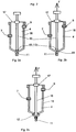
- FIG. 1a shows a preferred embodiment of the device.
- the media 2 to be filled are preferably provided in a flexible storage container 3 made of film, ie in a bag, which is connected to the measuring container 4 via the first and second communicating connection 5 and 6 to form a sterile unit.
- bags are known as containers for infusion solutions (eg, infusion bags or blood bags).
- the measuring container 4 can be made of a film, flexible bag.
- the storage container 3 and / or the measuring container 4 are dimensionally stable disposable or reusable containers made of a non-flexible material (eg plastic, glass, metal).
- the lower, the measure defining opening 7 of the Japanese matterers 4 is connected via the first connection 5 with the lower opening 8 of the reservoir, which communicates with the media to be filled 2 communicating.
- the upper Opening 9 of the Vietnamese mattersers 4 acts as an air outlet and leads via the second connection 6 from the upper part of the constitu mattersers to the upper opening 10 of the reservoir 3 , which lies above the media 2 to be filled in the reservoir 3 .
- This upper part of the reservoir 3 is filled with air.
- the measuring container 4 has a lockable outlet 11 , which is lower than the lower opening 7.
- the measuring container 4 is connected via the first and second connection 5 and 6 to the outside tightly and in a sterile manner to the reservoir 3 .
- connections 5 and 6 are hoses.
- the connection 6 between the upper opening 9 and the upper opening 10 of the storage androme mattersers can be omitted if the upper opening 9 is provided as an air outlet with a sterile, impermeable to the media gas filter or a ventilation valve, the or the air exchange with the surrounding environment, but does not allow germs and particles to penetrate.
- a predetermined volume of media 2 between storage and measuring containers 3 and 4 can be communicated per filling.
- the transfer of the media to be filled from the reservoir 3 in the measuring container 4 is possible here via the first connection 5 until at least the lower opening 7 of the Vietnamese mattersers 4 is covered by the media to be filled.
- lower opening 7 , the media to be filled 2 from the measuring container 4 in the reservoir 3 are transferable until the lower opening 7 is at least partially no longer covered by the media to be filled.
- the predetermined volume of media to be filled is geometrically determined by the space between the lower opening 7 of the Vietnamese mattersers 4 and the lockable outlet 11th
- the lockable outlet 11 is the controllable outlet valve 12th
- the controllable outlet valve 12 is a pinch valve. This reversibly compresses the cross section of the outwardly sealed, sterile connection 13 between the measuring and target containers 4 and 14 in a fluid-tight manner.
- the connection 13 is a flexible hose.
- the predetermined volume of media 2 in the measuring container 4 without contact with the surrounding environment in the target container 14 can be filled.
- the target container 14 may consist of a flexible disposable material or of a non-flexible, dimensionally stable reusable material.
- the media reach after opening the outlet valve 12 from the measuring container 4 on a fluid-tight, sterile way in the target container 14th
- the target container 14 can be closed to the hose (13) by mechanical and / or thermal and / or chemical action (eg, clamping, welding, gluing).
- the target container 14 is sterile separable from the measuring container 4 by cutting (eg, cutting) the closure, which has been produced by prior exposure to the tube 13 .
- FIG. 1b shows the filling of the Wenn mattersers 4 after lifting the reservoir 3 representing a bag , as far as and until the lower opening 7 of the Vietnamese mattersers 4 is covered by the media 2 to be filled.
- the media to be filled flow from the storage container 3 into the measuring container 4 via the first connection 5 , which represents a hose, wherein the media level in the storage container 3 lies above the lower opening 7 of the measuring container 4 .
- the air enters from the measuring container 4 via the second connection 6 representing a hose into the storage container 3 .
- the lockable outlet 11 in the form of the pinch valve 12 is closed.
- the media level in the measuring container 4 rises above the lower opening 7 .
- the reservoir 3 When the media in the measuring container 4 are above the lower opening 7 , the reservoir 3 is lowered, so that the level of the media to be filled in the reservoir 3 is lower than the lower opening 7 of the mecanic matterers. 4 In this position, the media to be filled 2 run through the lower opening 7 via the connection 5 back into the reservoir 3. From the reservoir 3 passes through the second connection 6 air in the measuring container 4. The liquid from the measuring container 4 runs back into the reservoir 3 , until the lower opening 7 is at least partially exposed and can be sucked through this no more media to be filled from the measuring container.
- Figure 1c shows this state after passing through steps A) and B).
- the measuring container 4 contains after Figure 1c a predetermined by the geometric conditions of the constituent mattersers, given volume, which is given by the space between the upper edge of the lower opening 7 of the Vietnamese mattersers 4 and the lockable outlet 11 .
- Figure 1d shows the sterile transfer of the media to be filled 2 from the measuring container 4 in the at least one target container 14 after passing through step C) and during the course of step D).
- the pressure of the controllable outlet valve 12 on the sterile connection 13 representing, preferably thermoplastic tube is very small, the barrier of the tube is released and the media to be filled flow from the measuring container 4 via the hose into the target container 14 .
- the target container 14 is subsequently separated by welding the thermoplastic tube, preferably with a blood bag, sterile from the measuring container 4 .
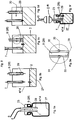
- FIG. 2a shows a preferred embodiment of the device according to the invention, in which the outlet 11 in the bottom of the Vietnamese mattersers 4 by a controllable outlet valve 12 in the measuring container 4 can be shut off.
- the lockable outlet 11 of the Vietnamese mattersers is closed by a stamp 15 .
- a punch rod 16 passes through a lid 17 of the Vietnamese mattersers 4 close to the outside.
- the lid is preferred flexible or the upper part of the Vietnamese mattersers 4 is deformed by an accordion-like design (bellows) in the direction of the punch rod 16 (not shown).
- the design is primarily determined by the length of the punch rod 16 such that the punch 15 is pressed by the elasticity of the lid 17 or the wall 18 on the lockable outlet 11 and closes it tight.
- Figure 2c shows an embodiment in which in the closed state of the lockable outlet 11 in the die rod 16, a tensile force F prevails.
- a pressure on the outer part of the punch rod of the lid of theitz mattersers 4 is deformable.
- the tensile force to the compressive force and the controllable outlet valve 12 opens.
- FIG. 3a represents a measuring container, which is sterile and fluid-tight connected to a target container 14 .
- the sterile connection 13 which connects the measuring container 4 sterile with the target container 14 is a tube 20 , the blunt opening 21 is closed in the bottom of the former mattersers 4 by a punch 15 .
- the tip of the tube 22 is sterile in the target container 14 inserted.
- the tube 20 is a through a Septum performing cover 23 inserted into the target container 14 .
- the target container 14 can be separated from the measuring container 4 in a sterile manner by pressing and / or by sealingly cutting through the tube 20 .
- a sterile closure 24 for the target container 14 can be generated.
- a sterile closure of the target container 14 can be produced by pulling the tube 20 out of the septum-forming lid 23 .
- the bracket 25 For stabilization measure and target containers are fixed by the bracket 25 .
- the tube 20 is a plastic or metal needle.
- FIG. 4a shows a further preferred embodiment of the device 1 according to the invention, in which measure and target containers are identical and in which the lower opening 7 and the upper opening 9 are integrated into a double line.
- the double line is sterile by a, preferably a septum performing lid 23 inserted into the target container 14 , particularly preferably in the manufacture of the lid 23 and before the sterilization of the device 1.
- the opening 7 is a tube, via which the media to be filled 2 on the first Connection 5 with the reservoir 3 are interchangeable.
- Opening 9 is a tube, via which air via the second connection 6 with the reservoir 3 is interchangeable.
- the smaller-width tube (inner tube), which is the opening 7 is coaxially located in the larger-width tube, which is the opening 9 .
- the larger-width tube constitutes the outer pipe of the double pipe formed by the space between the outer wall of the inner pipe and the inner wall of the outer pipe.
- Inner and outer ducts are outside of the transformers 4 components of fittings 26 to which the hoses performing connections 5 and 6 are attached (eg., By gluing).
- the tube with smaller clear width has a smaller distance to the bottom 27 of the Exammicers 4 than the tube with a larger clear width.
- the predetermined volume of media to be filled is equal to the space between the tip of the tube, the opening 7 is, and the bottom 27 of the complicat thinkingers. 4
- Fig. 4b represents this preferred embodiment after the end of a filling process.
- the preferably made of plastic, more preferably thermoplastic parts of the fittings 26 outside the Exam examplesers 4 are by welding and cutting, z. B. with a welding gun, in a sterile closure 24 can be transferred.
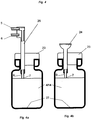
- FIG. 5a illustrates an embodiment of the device 1 in which the upper opening 9 is a tube 28 which has a porous, gas-permeable but impermeable material 29 for the media to be filled.
- This gas-permeable material is preferably a hydrophobic gas filter membrane, particularly preferably a Teflon membrane.
- the measuring container 4 has as in FIG. 4 at the same time the function of the target container 14th To FIG.
- the bottoms 2 to be filled are transferred to the target container 14 via the lower opening 7, which likewise represents a tube.
- the air displaced from the target container 14 leaves the tube 28 via the gas-permeable material 29 .
- the porous, gas-permeable material 29 containing part of the tube 28 this material 29 is wetted by the media 2 and impermeable to gas. The wetting blocks the further exchange of air via the upper opening 9 and falsifies the total volume balance by standing in the lower opening 7 media. 2 Because no more air can be discharged from the target container, no media 2 more in the target container 14 can be transferred.
- a gas pressure is generated, wherein the gas comes from the upper part of the reservoir 3 . Since no gas can pass through the medium wetted by the media gas filter 29 , opens by the gas pressure generation according to FIG. 5d a check valve 30 and through this gas enters the target container 14 , whereby the media from the first compound 5 are transported in the direction of reservoir until the media level in the target container 14 reaches the lower end of the opening 7. Then air enters through the media to be filled in Target container 14 and the return and the filling process are completed.
- the check valve 30 consists of an elastic ring 31 which lies in a groove 32 around the tube 28 and below which a small bore 33 leads from the bottom of the groove into the interior of the tube. If the pressure in the interior of the tube is greater than outside the tube, air passes through the bore 33 under the ring 31 to the outside.
- the check valve 30 is preferably located in the portion of the tube 28 located in the target container.
- a capillary bore or throttle (not shown) is preferably provided above the gas-permeable material 29 by laser shot into the target-container-side part of the tube 28 .
- the capillary-shaped bore or throttle has the function that when wetting the hydrophobic filter by entering the target container 14 media 2, the inflow of the media is not completely stopped, but only greatly slowed down.
- the predetermined volume in the target container is determined by its geometry, preferably by the space between the lower part of the gas-permeable material 29 and the bottom 27 of the target container 14 .
- the target container is preferably closed by pinch welding the two tubes 7 and 9 to a sterile closure 24 as in FIG. 5f shown.
- FIG. 6a shows a target container 14 , which is also transformer concernser, with the first and second connection 5 and 6 during the filling process.
- the upper and lower openings 9 and 7 are each tubes, with the lower opening 7 adjacent to the wall 18 of the target container 14 .
- FIG. 6b represents the target container in the overfilled state. Upon reaching this state, the return of the media to be filled 2 is introduced into the reservoir 3 . The return promotion takes place by pressure generation in the upper opening 9 or by negative pressure generation in the lower opening. 7 Across from FIG. 6a the flow direction in the first connection 5 reverses. In FIG. 6c is the return promotion far expired until the lower opening 7 is exposed and air passes, which stops the return promotion.
- FIG. 6b represents the target container in the overfilled state.
- the return promotion takes place by pressure generation in the upper opening 9 or by negative pressure generation in the lower opening.
- 7 Across from FIG. 6a the flow direction in the first connection 5 reverses.
- FIG. 6c is the return promotion far expired until the lower opening 7
- FIG. 6d represents a target container 14 , which is also a transformer in the tilted state.
- the tilt angle is b, which is to count positive counterclockwise.
- a positive tilt angle b as in FIG. 6d shown results in comparison to FIG. 6c , in which the tilt angle b of the constituent mattersers is equal to zero, one by an additional volume .DELTA.V larger, predetermined volume.
- b is negative.
- FIG. 7 shows an embodiment of the device 1 according to the invention, in which the predetermined volume can be varied by changing the height H of the lower opening 7 in the measuring container 4 .
- the passage of the connection 5 through the cover 17 of the Vietnamese mattersers 4 is here by a bellows 34 which allows a linear movement, sealed.
- An external mechanical adjusting device (not shown) makes it possible to change the distance of the lower opening 7 to the lockable outlet 11 . If the diameter of the measuring container inside is equal to d i , the predetermined volume changes with the height H by ⁇ / 4 * d i 2 * H. This linear relationship makes it possible to provide the mechanical adjusting device with a displacement measuring system and to precisely set the predetermined volume over it ,
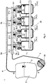
- FIG. 8 shows a device 1 according to the invention for the sterile filling of multiple target containers in a further development of FIG. 4 , Also in this embodiment, the target container 14 at the same time has the function of aitz livingers. To FIG. 8 four target container 14.1-4 are shown, in principle, the number of target containers to be filled is not limited.
- the media 2 to be filled are located in a flexible storage container 3 . All lower openings 7.1-4 of the measure and at the same time target containers 4.1-4 or 14.1-4 are connected to a first manifold 5a .
- the collecting line 5a which is preferably a plastic molding, is connected via the hose 5 representing a connection with the lower opening 8 of the bag-shaped reservoir 3 and thus with the media to be filled.
- the storage container 3 For filling, for example, the storage container 3 is lifted to such an extent that the media flow through the first communicating connection 5 into the target containers 14.1-4 to be filled.
- the upper openings / air outlets 9.1-4 of the measuring and target containers 4.1-4 and 14.1-4 are also brought together in a second manifold 6a , which is preferably a plastic molding .
- the collecting line 6a connects the hose 2 representing a second connection 6 with the upper opening 10 of the reservoir 3 and so with the air space in the reservoir.
- the air from the target containers 14.1-4 occurs during the filling process via the manifold 6a and the connection 6 again in the reservoir 3 a.
- the entire device 1 is closed, there is no interruption of the sterility limit.
- the storage container 3 is lowered until the media level in the storage container 3 is lower than the lower openings 7.1-4 of the target containers 14.1-4. Then run above the lower openings 7.1-4 standing in the target containers media back into the reservoir 3 .
- FIG. 9 shows a further, particularly preferred embodiment of the device 1 with several, here four target containers 14.1-4.
- a reversible pump 36 to be used for the adjustment preferably a peristaltic pump not contacting the media, is placed in the first connection 5 .
- valves 37.1-4 which act on the supply lines 38.1-4 of each measure and at the same time target container 4.1-4 or 14.1-4 , can be used.
- the filling process is such that only the valve is opened in conjunction with the lower opening 7 of the target container 14 to be filled.
- the pump 36 then conveys the media 2 from the reservoir 3 into the target container 14 until the lower opening 7 of the target container 14 is covered by the media to be filled.
- the pumping direction is switched and the pump 36 sucks media from the target container 14 again.
- the suction takes place only until the lower opening 7 is exposed. If this is free, the suction and dosing process is completed.
- the valve 37.1 in the supply line 38.1 is closed again and after opening the valve 37.2 in the supply line 38.2 of the next target container 14.2 this is then filled.
- the target containers 14.1-4 are in the following states: 14.1 not yet filled, valve 37.1 closed, 14.2 not yet completely filled, valve 37.2 closed, 14.3 in the adjustment phase, the associated valve 37.3 is open, the pump 36 sucks media from the target container 14.3 , until the lower opening 7.3 is exposed , 14.4 filled and balanced, valve 37.4 is closed.
- the filling of the target container 14 can, if the compound 5 is not inserted in the pump 36 , also carried out by lifting the reservoir, ie all target container 14.1-4 are filled in parallel until the lower openings 7.1-4 are covered. All valves 37.1-4 are open. After inserting the compound 5 in the pump 36 then the adjustment of each target container 14.1-4 is carried out individually as described for the adjustment phase .
- the sterile closure of the filled target container 14.1-4 is preferably carried out as in FIG. 4 described.
- FIG. 10 represents five target container 14.1-5 in the plan and a reservoir (bag, 3 ).
- the target containers are connected here via annular shaped pieces 5b and 6b with each other and with the reservoir 3 .
- the fittings lead hoses and / or extensions 39.1-5 and 40.1-5 to the target containers 14.1-5.
- valves 41.1-5 are arranged, which act so that they reversibly close or release the extensions 39 of the fittings 6b and thus act as Schlauchquetschventile. Structure and function correspond to the rest of the FIG. 8 ,
- the pump 36 for the adjustment of the predetermined volume acts on the connection 6 a. After filling, the filled target containers 14.1-5 , as in the FIGS.
- FIGS. 8 . 9 and 10 allow the sterile filling of media 2 in any number target containers 14.1-n, which also have the function of mecanicaln 4.1-n .
- the construction of a lockable spout 11 in the target container is unnecessary, because for the filling of the media 2 in the target container 14.1-n respectively a lower and upper opening 7 and 9 are sufficient.
Landscapes
- Physics & Mathematics (AREA)
- Fluid Mechanics (AREA)
- General Physics & Mathematics (AREA)
- External Artificial Organs (AREA)
- Basic Packing Technique (AREA)
- Medical Preparation Storing Or Oral Administration Devices (AREA)
- Details Of Rigid Or Semi-Rigid Containers (AREA)
Claims (19)
- Dispositif (1) d'embouteillage dosé de milieux, comprenant :- au moins un récipient de stockage (3) pour les milieux à embouteiller (2) avec une ouverture inférieure (8), située en partie basse du récipient de stockage et une ouverture supérieure (10), située en partie haute du récipient de stockage, dans lequel au moins l'ouverture inférieure (8) est en liaison de communication avec le stockage au niveau des milieux à embouteiller (2),- au moins un récipient de mesure (4) prévu avec un orifice de sortie obturable (11) pour les milieux à embouteiller (2), qui est équipé d'une ouverture supérieure (9) et d'une ouverture inférieure (7) située en-dessous de celle-ci et définissant la mesure,- une première liaison de communication (5) entre les ouvertures inférieures (8, 7) de l'au moins un récipient de stockage et de l'au moins un récipient de mesure,- une seconde liaison de communication (6) entre les ouvertures supérieures (10) et (9) de l'au moins un récipient de stockage et de l'au moins un récipient de mesure, ou une liaison des ouvertures supérieures infranchissable vers l'environnement pour les milieux à embouteiller,dans lequel le dispositif est conçu pour
faire passer un volume prédéfini des milieux à embouteiller (2), qui correspond à l'espace entre l'ouverture inférieure (7) de l'au moins un récipient de mesure (4) et l'orifice de sortie obturable (11), via l'orifice de sortie obturable (11), dans au moins un récipient cible (14),
et dans lequel le dispositif est conçu pour
augmenter, par inclinaison du récipient de mesure (4) selon un angle d'inclinaison positif dans le sens contra-horaire, le volume prédéfini par rapport au volume prédéfini à un angle d'inclinaison de 0°,
et dans lequel le dispositif est conçu pour
réduire, par inclinaison du récipient de mesure (4) selon un angle d'inclinaison négatif dans le sens contra-horaire, le volume prédéfini par rapport au volume prédéfini à un angle d'inclinaison de 0°. - Dispositif (1) selon la revendication 1, dans lequel le dispositif (1) présente des moyens pour exercer au moins une force sur les milieux à embouteiller (2), de sorte que ceux-ci peuvent être communiqués entre l'au moins un récipient de stockage (3) et l'au moins un récipient de mesure (4).
- Dispositif (1) selon la revendication 2, dans lequel les moyens servent à produire une différence de pression entre le récipient de stockage (3) et le récipient de mesure (4), pour que les milieux à embouteiller (2) puissent être communiqués entre l'au moins un récipient de stockage (3) et l'au moins un récipient de mesure (4).
- Dispositif selon la revendication 2, dans lequel le dispositif est conçu de sorte que les milieux à embouteiller (2) peuvent être communiqués entre l'au moins un récipient de stockage (3) et l'au moins un récipient de mesure (4) par des moyens permettant d'exercer au moins une force sur le récipient de stockage (3) et/ou sur l'au moins une première liaison (5) et/ou sur l'au moins une seconde liaison (6).
- Dispositif selon la revendication 4, dans lequel le dispositif est conçu de sorte que les milieux à embouteiller (2) peuvent être alimentés à l'au moins un récipient de mesure (4) via la première liaison (5) par l'exercice d'au moins une force, jusqu'à ce que au moins l'ouverture inférieure (7) du récipient de mesure (4) soit totalement recouverte par les milieux à embouteiller (2) et de sorte que les milieux à embouteiller (2) peuvent être renvoyés dans l'au moins un récipient de stockage (3) via la première liaison (5) par l'exercice d'au moins une force, jusqu'à ce que l'ouverture inférieure (7) du récipient de mesure (4) ne soit au moins partiellement plus recouverte par les milieux à embouteiller (2) et de sorte qu'aucun milieu à embouteiller (2) ne peut être échangé entre l'au moins un récipient de stockage (3) et l'au moins un récipient de mesure (4) lorsqu'une ouverture inférieure (7) du récipient de mesure (4) n'est recouverte que partiellement par les milieux à embouteiller (2) .
- Dispositif selon la revendication 4, dans lequel l'exercice d'au moins une force est une compression de l'au moins un récipient de stockage (3).
- Dispositif selon la revendication 5, dans lequel une différence de pression peut être produite par l'exercice d'au moins une force en levant l'au moins un récipient de stockage (3) et dans lequel, une fois ce levage effectué avec succès, le niveau des milieux à embouteiller (2) dans l'au moins un récipient de stockage (3) est supérieur à l'ouverture inférieure (7) de l'au moins un récipient de mesure (4).
- Dispositif selon la revendication 5, dans lequel une différence de pression peut être produite par l'exercice d'au moins une force en abaissant l'au moins un récipient de stockage (3) et dans lequel, une fois cet abaissement effectué avec succès, le niveau des milieux à embouteiller (2) dans l'au moins un récipient de stockage (3) est inférieur à l'ouverture inférieure (7) de l'au moins un récipient de mesure (4).
- Dispositif selon la revendication 4, dans lequel l'exercice d'au moins une force sur la première liaison (5) et/ou sur la seconde liaison (6) est l'exercice d'une pompe à tuyau et/ou d'une pompe péristaltique (36) sur une liaison par tuyau.
- Dispositif selon la revendication 1, dans lequel l'au moins un récipient de stockage (3) et/ou l'au moins un récipient de mesure (4) et/ou l'au moins un récipient cible (14) est un récipient jetable flexible.
- Dispositif selon la revendication 1, dans lequel l'éloignement de l'ouverture inférieure (7) par rapport à l'orifice de sortie obturable (11), et par conséquent la quantité du volume prédéfini, peuvent être ajustés de façon variable par réglage en hauteur de l'ouverture inférieure (7).
- Dispositif selon la revendication 11, dans lequel l'ouverture inférieure (7) est située dans une paroi flexible (18) de l'au moins un récipient de mesure (4) et dans lequel l'éloignement de l'ouverture inférieure (7) par rapport à l'orifice de sortie obturable (11) peut être varié par l'exercice d'au moins une force.
- Dispositif selon la revendication 11, dans lequel l'ouverture inférieure (7) de l'au moins un récipient de mesure (4) est un tuyau dans un capot (17) du récipient de mesure (4) partiellement conçu sous forme de soufflet (34) et dans lequel l'éloignement de l'ouverture inférieure (7) par rapport à l'orifice de sortie obturable (11) peut être varié par exercice d'une pression sur le soufflet (34).
- Dispositif selon la revendication 1, dans lequel l'au moins une première liaison (5) entre l'ouverture inférieure (7) du récipient de mesure et l'ouverture inférieure (8) du récipient de stockage est une liaison par tuyau étanche vers l'extérieur.
- Dispositif selon la revendication 1, dans lequel l'au moins une seconde liaison (6) entre l'ouverture supérieure (9) du récipient de mesure et l'ouverture supérieure (10) du récipient de stockage est une liaison par tuyau étanche vers l'extérieur.
- Dispositif selon la revendication 1, dans lequel le récipient de mesure (4) est relié au récipient cible (14) via une liaison (13) étanche vers l'extérieur.
- Dispositif selon l'une quelconque des Revendications 1 à 16, dans lequel plusieurs récipients de mesure (4.1) et/ou récipients cibles (14.1) peuvent être remplis successivement avec n milieux à embouteiller (2) via au moins une première liaison (5) depuis l'au moins un récipient de stockage (3) et dans lequel n est un nombre entier positif supérieur à un.
- Procédé d'embouteillage dosé de milieux au moyen d'un dispositif (1) selon l'une quelconque des revendications 1 à 17, comprenant les étapes consistant à :A) produire un flux au niveau des milieux à embouteiller (2) depuis le récipient de stockage (3) vers le récipient de mesure (4) jusqu'à ce qu'au moins l'ouverture inférieure (7) du récipient de mesure (4) soit totalement recouverte par les milieux à embouteiller (2),B)produire un flux au niveau des milieux à embouteiller (2) depuis le récipient de mesure (4) vers le récipient de stockage (3) jusqu'à ce que l'ouverture inférieure (7) du récipient de mesure (4) ne soit au moins partiellement plus recouverte par les milieux à embouteiller (2) et qu'un volume prédéfini de milieux à embouteiller (2) se trouve dans le récipient de mesure (4),C)ouvrir l'orifice de sortie obturable (11) etD) faire passer le volume prédéfini de milieux à embouteiller (2) du récipient de mesure (4) à l'au moins un récipient cible (14),dans lequel les étapes A) et B) sont effectuées par l'exercice d'au moins une force sur les milieux à embouteiller (2),
dans lequel les étapes A) à D) sont réalisées en n cycles,
et dans lequel n est un nombre entier positif supérieur ou égal à un. - Procédé selon la revendication 18,
dans lequel, après l'étape D) du n-ième cycle, la liaison par tuyau (13) entre le récipient de mesure (4) et le récipient cible (14) est fermée hermétiquement par action thermique et/ou mécanique et/ou par encollage du récipient de mesure (4) et du récipient cible (14).
Applications Claiming Priority (2)
| Application Number | Priority Date | Filing Date | Title |
|---|---|---|---|
| DE102006054606.7A DE102006054606B4 (de) | 2006-11-21 | 2006-11-21 | Vorrichtung und Verfahren zum dosierten Abfüllen von Medien |
| PCT/EP2007/009504 WO2008061614A2 (fr) | 2006-11-21 | 2007-11-02 | Dispositif et procédé permettant de transvaser des milieux de manière dosée |
Publications (2)
| Publication Number | Publication Date |
|---|---|
| EP2097722A2 EP2097722A2 (fr) | 2009-09-09 |
| EP2097722B1 true EP2097722B1 (fr) | 2018-01-10 |
Family
ID=39326116
Family Applications (1)
| Application Number | Title | Priority Date | Filing Date |
|---|---|---|---|
| EP07819531.0A Active EP2097722B1 (fr) | 2006-11-21 | 2007-11-02 | Dispositif et procédé permettant de transvaser des milieux de manière dosée |
Country Status (4)
| Country | Link |
|---|---|
| US (1) | US8087596B2 (fr) |
| EP (1) | EP2097722B1 (fr) |
| DE (1) | DE102006054606B4 (fr) |
| WO (1) | WO2008061614A2 (fr) |
Families Citing this family (6)
| Publication number | Priority date | Publication date | Assignee | Title |
|---|---|---|---|---|
| FR2956092B1 (fr) | 2010-02-10 | 2012-02-24 | Sartorius Stedim Biotech Sa | Procede et unite d'emplissage sterile d'un conteneur elementaire final avec un contenu destine au domaine biopharmaceutique. |
| DE102013010509A1 (de) | 2013-06-22 | 2014-12-24 | Uwe Schrader | Schlauchsystem |
| US9468892B2 (en) | 2014-02-07 | 2016-10-18 | Hydra-Flex, Inc. | Modular chemical dispensing assembly |
| JP6983454B2 (ja) | 2016-09-30 | 2021-12-17 | サイティバ・スウェーデン・アクチボラグ | 分離樹脂の移送のための方法およびシステム |
| CN117490663A (zh) * | 2023-11-15 | 2024-02-02 | 黄河水文水资源科学研究院 | 一种应用于河道测量的水深测量仪器 |
| CN119218472B (zh) * | 2024-11-15 | 2025-09-26 | 四川科伦药业股份有限公司 | 一种双蝶阀无菌药物转移系统及无菌药物转移方法 |
Family Cites Families (11)
| Publication number | Priority date | Publication date | Assignee | Title |
|---|---|---|---|---|
| US1657792A (en) * | 1926-04-28 | 1928-01-31 | L A Ice And Cold Storage Compa | Bottle filler |
| FR1534009A (fr) | 1967-06-14 | 1968-07-26 | Ct De Rech S De Pont A Mousson | Dispositif de distribution d'un liquide par soutirage en atomosphère inerte |
| US3893625A (en) * | 1974-07-01 | 1975-07-08 | Gyromat Corp | Pumpless recirculating system for flowable materials |
| DE2713525A1 (de) * | 1977-03-26 | 1978-09-28 | Krupp Gmbh | Verfahren und vorrichtung zum abfuellen vorbestimmter fluessigkeiten |
| DE3245594A1 (de) * | 1982-12-09 | 1984-06-14 | Bremerland Molkerei eG, 2800 Bremen | Verfahren zur dosierten abgabe von frischmilch im selbstbedienungsverfahren |
| DE4023998A1 (de) * | 1990-07-28 | 1992-01-30 | Alfill Getraenketechnik | Verfahren und vorrichtung zum abfuellen einer fluessigkeit in portionsbehaelter |
| US5090594A (en) | 1991-01-15 | 1992-02-25 | Flowclean Equipment, Inc. | Volumetric fluid dispensing apparatus and method |
| US5584327A (en) * | 1994-07-06 | 1996-12-17 | Ecolab Inc. | Method and apparatus for storing and dispensing chemical solutions |
| DE69532920T2 (de) | 1995-05-30 | 2005-04-14 | Ivek Corp. | Vorrichtung zur volumetrischen Abgabe von Flüssigkeiten |
| FR2784669B1 (fr) * | 1998-10-16 | 2001-01-05 | Remy Equipement | Procede de controle du remplissage de recipients avec un produit coulant et installation de remplissage mettant en oeuvre ce procede |
| JP2007524806A (ja) | 2003-02-24 | 2007-08-30 | ミリポア・コーポレイション | 流体容積を連続的に測定するための手段を有する流体分注装置 |
-
2006
- 2006-11-21 DE DE102006054606.7A patent/DE102006054606B4/de not_active Expired - Fee Related
-
2007
- 2007-11-02 US US12/311,809 patent/US8087596B2/en active Active
- 2007-11-02 WO PCT/EP2007/009504 patent/WO2008061614A2/fr not_active Ceased
- 2007-11-02 EP EP07819531.0A patent/EP2097722B1/fr active Active
Also Published As
| Publication number | Publication date |
|---|---|
| EP2097722A2 (fr) | 2009-09-09 |
| DE102006054606A1 (de) | 2008-05-29 |
| US20100175774A1 (en) | 2010-07-15 |
| WO2008061614A2 (fr) | 2008-05-29 |
| DE102006054606B4 (de) | 2019-06-06 |
| WO2008061614A3 (fr) | 2008-07-10 |
| US8087596B2 (en) | 2012-01-03 |
Similar Documents
| Publication | Publication Date | Title |
|---|---|---|
| EP3258223B1 (fr) | Dispositif de dosage pour un système d'infusion | |
| DE102012209314B4 (de) | Vorrichtung und Verfahren zur Abgabe oder Aufnahme eines Flüssigkeitsvolumens | |
| EP3050585B1 (fr) | Appareil de dosage destiné à la distribution d'un fluide dans des conditions aseptiques | |
| DE69032869T2 (de) | Verbessertes debitregelungssystem durch druckmessung | |
| EP2788046B1 (fr) | Pompe pour butes médicales | |
| EP1448252B1 (fr) | Ensemble pompe medicale | |
| DE4336336A1 (de) | Kasetteninfusionssystem | |
| DE2743044A1 (de) | Vorrichtung zum abgeben von fluessigkeitsstroemen mit regelbarer geschwindigkeit | |
| WO2008061614A2 (fr) | Dispositif et procédé permettant de transvaser des milieux de manière dosée | |
| DE10335146B4 (de) | Vorrichtung und Verfahren zum dosierten Ausbringen eines viskosen Mediums | |
| CH703127A1 (de) | Dispenser und Verfahren zum Abgeben von fliess- oder rieselfähigen Materialien. | |
| EP3313248B1 (fr) | Distributeur comprenant un module côté fluide et un module sec | |
| EP2535071B1 (fr) | Dispositif de médication pour la distribuer dosée d'un fluide | |
| EP2086689B1 (fr) | Unité soupape destinée à interrompre ou à libérer l'écoulement d'un fluide le long d'un conduit creux, son utilisation dans un système de dosage permettant un débit dosé dudit fluide, et procédé de mise en oeuvre associé | |
| DE102005045393B4 (de) | Verfahren zum Dosieren von Lösungen | |
| EP0997643B1 (fr) | Pompe doseuse à membrane | |
| DE202007014392U1 (de) | Vorrichtung zum dosierten Abfüllen von Medien | |
| DE19906409A1 (de) | Dosiervorrichtung sowie Verfahren zum Betreiben einer Dosiervorrichtung | |
| DE102007010412B4 (de) | Vorrichtung und Verfahren zum Dosieren von Flüssigkeiten in gasgefüllte Räume | |
| DE69532920T2 (de) | Vorrichtung zur volumetrischen Abgabe von Flüssigkeiten | |
| DE19632348C1 (de) | Kolbenbürette | |
| EP0947207B1 (fr) | Dispositif d'administration sans pulsations pour fluides stériles | |
| WO2007000064A1 (fr) | Dispositif de micro-dosage pour matieres liquides | |
| DE102010004068B9 (de) | Verfahren und Befüllvorrichtung zum Befüllen einer Kartusche mit zumindest einem Material | |
| DE202024102985U1 (de) | Modul für die Förderung eines Fluids |
Legal Events
| Date | Code | Title | Description |
|---|---|---|---|
| PUAI | Public reference made under article 153(3) epc to a published international application that has entered the european phase |
Free format text: ORIGINAL CODE: 0009012 |
|
| 17P | Request for examination filed |
Effective date: 20090622 |
|
| AK | Designated contracting states |
Kind code of ref document: A2 Designated state(s): AT BE BG CH CY CZ DE DK EE ES FI FR GB GR HU IE IS IT LI LT LU LV MC MT NL PL PT RO SE SI SK TR |
|
| DAX | Request for extension of the european patent (deleted) | ||
| 17Q | First examination report despatched |
Effective date: 20100422 |
|
| GRAP | Despatch of communication of intention to grant a patent |
Free format text: ORIGINAL CODE: EPIDOSNIGR1 |
|
| INTG | Intention to grant announced |
Effective date: 20170927 |
|
| GRAS | Grant fee paid |
Free format text: ORIGINAL CODE: EPIDOSNIGR3 |
|
| GRAA | (expected) grant |
Free format text: ORIGINAL CODE: 0009210 |
|
| AK | Designated contracting states |
Kind code of ref document: B1 Designated state(s): AT BE BG CH CY CZ DE DK EE ES FI FR GB GR HU IE IS IT LI LT LU LV MC MT NL PL PT RO SE SI SK TR |
|
| REG | Reference to a national code |
Ref country code: GB Ref legal event code: FG4D Free format text: NOT ENGLISH |
|
| REG | Reference to a national code |
Ref country code: CH Ref legal event code: EP Ref country code: AT Ref legal event code: REF Ref document number: 962914 Country of ref document: AT Kind code of ref document: T Effective date: 20180115 |
|
| REG | Reference to a national code |
Ref country code: IE Ref legal event code: FG4D Free format text: LANGUAGE OF EP DOCUMENT: GERMAN |
|
| REG | Reference to a national code |
Ref country code: DE Ref legal event code: R096 Ref document number: 502007016019 Country of ref document: DE |
|
| REG | Reference to a national code |
Ref country code: NL Ref legal event code: MP Effective date: 20180110 |
|
| PG25 | Lapsed in a contracting state [announced via postgrant information from national office to epo] |
Ref country code: NL Free format text: LAPSE BECAUSE OF FAILURE TO SUBMIT A TRANSLATION OF THE DESCRIPTION OR TO PAY THE FEE WITHIN THE PRESCRIBED TIME-LIMIT Effective date: 20180110 |
|
| PG25 | Lapsed in a contracting state [announced via postgrant information from national office to epo] |
Ref country code: FI Free format text: LAPSE BECAUSE OF FAILURE TO SUBMIT A TRANSLATION OF THE DESCRIPTION OR TO PAY THE FEE WITHIN THE PRESCRIBED TIME-LIMIT Effective date: 20180110 Ref country code: CY Free format text: LAPSE BECAUSE OF FAILURE TO SUBMIT A TRANSLATION OF THE DESCRIPTION OR TO PAY THE FEE WITHIN THE PRESCRIBED TIME-LIMIT Effective date: 20180110 Ref country code: ES Free format text: LAPSE BECAUSE OF FAILURE TO SUBMIT A TRANSLATION OF THE DESCRIPTION OR TO PAY THE FEE WITHIN THE PRESCRIBED TIME-LIMIT Effective date: 20180110 Ref country code: LT Free format text: LAPSE BECAUSE OF FAILURE TO SUBMIT A TRANSLATION OF THE DESCRIPTION OR TO PAY THE FEE WITHIN THE PRESCRIBED TIME-LIMIT Effective date: 20180110 |
|
| PG25 | Lapsed in a contracting state [announced via postgrant information from national office to epo] |
Ref country code: BG Free format text: LAPSE BECAUSE OF FAILURE TO SUBMIT A TRANSLATION OF THE DESCRIPTION OR TO PAY THE FEE WITHIN THE PRESCRIBED TIME-LIMIT Effective date: 20180410 Ref country code: GR Free format text: LAPSE BECAUSE OF FAILURE TO SUBMIT A TRANSLATION OF THE DESCRIPTION OR TO PAY THE FEE WITHIN THE PRESCRIBED TIME-LIMIT Effective date: 20180411 Ref country code: IS Free format text: LAPSE BECAUSE OF FAILURE TO SUBMIT A TRANSLATION OF THE DESCRIPTION OR TO PAY THE FEE WITHIN THE PRESCRIBED TIME-LIMIT Effective date: 20180510 Ref country code: LV Free format text: LAPSE BECAUSE OF FAILURE TO SUBMIT A TRANSLATION OF THE DESCRIPTION OR TO PAY THE FEE WITHIN THE PRESCRIBED TIME-LIMIT Effective date: 20180110 Ref country code: SE Free format text: LAPSE BECAUSE OF FAILURE TO SUBMIT A TRANSLATION OF THE DESCRIPTION OR TO PAY THE FEE WITHIN THE PRESCRIBED TIME-LIMIT Effective date: 20180110 Ref country code: PL Free format text: LAPSE BECAUSE OF FAILURE TO SUBMIT A TRANSLATION OF THE DESCRIPTION OR TO PAY THE FEE WITHIN THE PRESCRIBED TIME-LIMIT Effective date: 20180110 |
|
| REG | Reference to a national code |
Ref country code: FR Ref legal event code: PLFP Year of fee payment: 12 |
|
| PG25 | Lapsed in a contracting state [announced via postgrant information from national office to epo] |
Ref country code: MT Free format text: LAPSE BECAUSE OF FAILURE TO SUBMIT A TRANSLATION OF THE DESCRIPTION OR TO PAY THE FEE WITHIN THE PRESCRIBED TIME-LIMIT Effective date: 20180110 |
|
| REG | Reference to a national code |
Ref country code: DE Ref legal event code: R097 Ref document number: 502007016019 Country of ref document: DE |
|
| PG25 | Lapsed in a contracting state [announced via postgrant information from national office to epo] |
Ref country code: RO Free format text: LAPSE BECAUSE OF FAILURE TO SUBMIT A TRANSLATION OF THE DESCRIPTION OR TO PAY THE FEE WITHIN THE PRESCRIBED TIME-LIMIT Effective date: 20180110 Ref country code: IT Free format text: LAPSE BECAUSE OF FAILURE TO SUBMIT A TRANSLATION OF THE DESCRIPTION OR TO PAY THE FEE WITHIN THE PRESCRIBED TIME-LIMIT Effective date: 20180110 Ref country code: EE Free format text: LAPSE BECAUSE OF FAILURE TO SUBMIT A TRANSLATION OF THE DESCRIPTION OR TO PAY THE FEE WITHIN THE PRESCRIBED TIME-LIMIT Effective date: 20180110 |
|
| PLBE | No opposition filed within time limit |
Free format text: ORIGINAL CODE: 0009261 |
|
| STAA | Information on the status of an ep patent application or granted ep patent |
Free format text: STATUS: NO OPPOSITION FILED WITHIN TIME LIMIT |
|
| PG25 | Lapsed in a contracting state [announced via postgrant information from national office to epo] |
Ref country code: CZ Free format text: LAPSE BECAUSE OF FAILURE TO SUBMIT A TRANSLATION OF THE DESCRIPTION OR TO PAY THE FEE WITHIN THE PRESCRIBED TIME-LIMIT Effective date: 20180110 Ref country code: SK Free format text: LAPSE BECAUSE OF FAILURE TO SUBMIT A TRANSLATION OF THE DESCRIPTION OR TO PAY THE FEE WITHIN THE PRESCRIBED TIME-LIMIT Effective date: 20180110 Ref country code: DK Free format text: LAPSE BECAUSE OF FAILURE TO SUBMIT A TRANSLATION OF THE DESCRIPTION OR TO PAY THE FEE WITHIN THE PRESCRIBED TIME-LIMIT Effective date: 20180110 |
|
| 26N | No opposition filed |
Effective date: 20181011 |
|
| PG25 | Lapsed in a contracting state [announced via postgrant information from national office to epo] |
Ref country code: SI Free format text: LAPSE BECAUSE OF FAILURE TO SUBMIT A TRANSLATION OF THE DESCRIPTION OR TO PAY THE FEE WITHIN THE PRESCRIBED TIME-LIMIT Effective date: 20180110 |
|
| REG | Reference to a national code |
Ref country code: CH Ref legal event code: PL |
|
| PG25 | Lapsed in a contracting state [announced via postgrant information from national office to epo] |
Ref country code: LU Free format text: LAPSE BECAUSE OF NON-PAYMENT OF DUE FEES Effective date: 20181102 Ref country code: MC Free format text: LAPSE BECAUSE OF FAILURE TO SUBMIT A TRANSLATION OF THE DESCRIPTION OR TO PAY THE FEE WITHIN THE PRESCRIBED TIME-LIMIT Effective date: 20180110 |
|
| REG | Reference to a national code |
Ref country code: BE Ref legal event code: MM Effective date: 20181130 |
|
| REG | Reference to a national code |
Ref country code: IE Ref legal event code: MM4A |
|
| PG25 | Lapsed in a contracting state [announced via postgrant information from national office to epo] |
Ref country code: CH Free format text: LAPSE BECAUSE OF NON-PAYMENT OF DUE FEES Effective date: 20181130 Ref country code: LI Free format text: LAPSE BECAUSE OF NON-PAYMENT OF DUE FEES Effective date: 20181130 |
|
| PG25 | Lapsed in a contracting state [announced via postgrant information from national office to epo] |
Ref country code: IE Free format text: LAPSE BECAUSE OF NON-PAYMENT OF DUE FEES Effective date: 20181102 |
|
| PG25 | Lapsed in a contracting state [announced via postgrant information from national office to epo] |
Ref country code: BE Free format text: LAPSE BECAUSE OF NON-PAYMENT OF DUE FEES Effective date: 20181130 |
|
| REG | Reference to a national code |
Ref country code: AT Ref legal event code: MM01 Ref document number: 962914 Country of ref document: AT Kind code of ref document: T Effective date: 20181102 |
|
| PG25 | Lapsed in a contracting state [announced via postgrant information from national office to epo] |
Ref country code: AT Free format text: LAPSE BECAUSE OF NON-PAYMENT OF DUE FEES Effective date: 20181102 |
|
| PG25 | Lapsed in a contracting state [announced via postgrant information from national office to epo] |
Ref country code: TR Free format text: LAPSE BECAUSE OF FAILURE TO SUBMIT A TRANSLATION OF THE DESCRIPTION OR TO PAY THE FEE WITHIN THE PRESCRIBED TIME-LIMIT Effective date: 20180110 |
|
| PG25 | Lapsed in a contracting state [announced via postgrant information from national office to epo] |
Ref country code: PT Free format text: LAPSE BECAUSE OF FAILURE TO SUBMIT A TRANSLATION OF THE DESCRIPTION OR TO PAY THE FEE WITHIN THE PRESCRIBED TIME-LIMIT Effective date: 20180110 |
|
| PG25 | Lapsed in a contracting state [announced via postgrant information from national office to epo] |
Ref country code: HU Free format text: LAPSE BECAUSE OF FAILURE TO SUBMIT A TRANSLATION OF THE DESCRIPTION OR TO PAY THE FEE WITHIN THE PRESCRIBED TIME-LIMIT; INVALID AB INITIO Effective date: 20071102 |
|
| P01 | Opt-out of the competence of the unified patent court (upc) registered |
Effective date: 20230526 |
|
| PGFP | Annual fee paid to national office [announced via postgrant information from national office to epo] |
Ref country code: DE Payment date: 20251118 Year of fee payment: 19 |
|
| PGFP | Annual fee paid to national office [announced via postgrant information from national office to epo] |
Ref country code: GB Payment date: 20251120 Year of fee payment: 19 |
|
| PGFP | Annual fee paid to national office [announced via postgrant information from national office to epo] |
Ref country code: FR Payment date: 20251120 Year of fee payment: 19 |