EP2097971B1 - Asynchronmotor-steuerung - Google Patents
Asynchronmotor-steuerung Download PDFInfo
- Publication number
- EP2097971B1 EP2097971B1 EP08750465A EP08750465A EP2097971B1 EP 2097971 B1 EP2097971 B1 EP 2097971B1 EP 08750465 A EP08750465 A EP 08750465A EP 08750465 A EP08750465 A EP 08750465A EP 2097971 B1 EP2097971 B1 EP 2097971B1
- Authority
- EP
- European Patent Office
- Prior art keywords
- circuit
- terminal
- motor
- voltage
- bidirectional switches
- Prior art date
- Legal status (The legal status is an assumption and is not a legal conclusion. Google has not performed a legal analysis and makes no representation as to the accuracy of the status listed.)
- Not-in-force
Links
Images

Classifications
-
- H—ELECTRICITY
- H02—GENERATION; CONVERSION OR DISTRIBUTION OF ELECTRIC POWER
- H02P—CONTROL OR REGULATION OF ELECTRIC MOTORS, ELECTRIC GENERATORS OR DYNAMO-ELECTRIC CONVERTERS; CONTROLLING TRANSFORMERS, REACTORS OR CHOKE COILS
- H02P25/00—Arrangements or methods for the control of AC motors characterised by the kind of AC motor or by structural details
- H02P25/02—Arrangements or methods for the control of AC motors characterised by the kind of AC motor or by structural details characterised by the kind of motor
- H02P25/04—Single phase motors, e.g. capacitor motors
-
- H—ELECTRICITY
- H02—GENERATION; CONVERSION OR DISTRIBUTION OF ELECTRIC POWER
- H02P—CONTROL OR REGULATION OF ELECTRIC MOTORS, ELECTRIC GENERATORS OR DYNAMO-ELECTRIC CONVERTERS; CONTROLLING TRANSFORMERS, REACTORS OR CHOKE COILS
- H02P1/00—Arrangements for starting electric motors or dynamo-electric converters
- H02P1/16—Arrangements for starting electric motors or dynamo-electric converters for starting dynamo-electric motors or dynamo-electric converters
- H02P1/42—Arrangements for starting electric motors or dynamo-electric converters for starting dynamo-electric motors or dynamo-electric converters for starting an individual single-phase induction motor
- H02P1/44—Arrangements for starting electric motors or dynamo-electric converters for starting dynamo-electric motors or dynamo-electric converters for starting an individual single-phase induction motor by phase-splitting with a capacitor
- H02P1/445—Arrangements for starting electric motors or dynamo-electric converters for starting dynamo-electric motors or dynamo-electric converters for starting an individual single-phase induction motor by phase-splitting with a capacitor by using additional capacitors switched at start up
Definitions
- the present invention generally relates to asynchronous motors and, more particularly, to controlling the speed and direction of rotation of a motor powered by an alternating voltage.
- asynchronous motor control devices require a bipolar relay type switch to reverse the direction of rotation of the motor. This increases the consumption of the system because, for one of the two directions of rotation, a current must supply the relay coil permanently.
- electromechanical relays generate noise and electromagnetic disturbances, are often expensive, and affect the integration of control devices.
- the document JP5220290 discloses a circuit for controlling the speed of a single-phase asynchronous motor.
- the present invention aims to overcome all or part of the disadvantages of the multi-speed and reversal control systems of an asynchronous motor.
- the invention aims more particularly to avoid the use of a relay control to reverse the direction of rotation of the motor.
- one of the bidirectional switches of the second circuit has its second conduction terminal directly connected to an application terminal of an AC voltage, the other bidirectional switches of the second circuit having their second conduction terminals. respective impedance connected to this terminal of application of the AC voltage.
- the bidirectional switches of the second circuit have their respective second conduction terminals connected, by an impedance, to an application terminal of the AC voltage.
- the number of bidirectional switches of the second circuit is equal to the number of rotation speeds desired for the motor minus one, an impedance directly connecting the common terminal to the application terminal of the AC voltage. .
- the number of bidirectional switches of the second circuit is equal to the number of rotational speeds desired for the motor.
- respective second ends of the motor windings are capable of being connected together to another terminal for applying the alternating voltage, a capacitive element connecting their respective first ends.
- each impedance includes at least one capacitive element in parallel with a resistive element.
- said bidirectional switches are triacs whose cathodes are directly connected to the common terminal.
- respective control terminals of the bidirectional switches are able to be connected to output terminals of a control circuit providing two-state signals.
- the invention also provides an apparatus having an asynchronous motor adapted to be powered by an alternating voltage and a control device in direction and speed of rotation, wherein respective first ends of windings of the stator of the motor are connected to the first terminals. respective conduction of the switches of the first circuit.
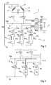
- the figure 1 represents, very schematically and in the form of blocks, an example of a typical control architecture of an asynchronous motor 1 (M) powered by an alternating voltage Vac, for example the voltage of the electrical distribution network 2.
- M asynchronous motor 1
- Vac alternating voltage
- Vac the voltage of the electrical distribution network 2.
- M asynchronous motor 1
- Vac the voltage of the electrical distribution network 2.
- Vac the voltage of the electrical distribution network 2.
- the speed selection circuit 3 receives several setpoints ( as much as possible speeds) of a control unit 5 (for example, a microcontroller MCU) powered by a low DC voltage Vcc.
- the unit 5 also generally controls the rotation direction inversion system (dotted line 55).
- the terminal 22 corresponds to the application terminal of the positive potential Vcc.
- the figure 2 represents an example of a usual electrical diagram of a control device of a motor 1 respecting the architecture of the figure 1 .
- the two windings 15 and 16 of the stator have been schematized by inductances.
- a winding 15 has an end 11 connected, via a capacitive element C17 fixing the phase difference between the power supplies of the windings, to the terminal 21 and its other end 12 is connected to the terminal 31 of the speed control circuit 3 .
- This circuit 3 is made from triacs T1, T2 and T3 respectively in series with cells 33 1 , 33 2 and 33 3 more or less modifying, according to the triac made passing, the impedance in series with the windings of the motor for change the speed of rotation.
- Each cell 33 includes, in parallel, a resistor R33 i (i being here between 1 and 3) and the series association of a capacitive element C33 i and a resistor R'33 i .
- the impedance variation is mainly ensured by the capacitive elements, the resistances being able to be identical from one cell to another.
- Resistors R'33 i are mainly used to limit the inrush current at startup.
- Resistors R33 i serve to discharge the capacitive element of a cell when it is no longer used.
- the resistors R33 i have values greater than the resistors R'33 i (in a ratio of at least 5).
- the cells are connected on the one hand to the terminal 31 and on the other hand to the anode A i of the corresponding triac Ti.
- the cathode K i of each triac Ti is connected directly to the terminal 22, also connected to an application terminal of a positive potential Vcc.
- the anode A i of each triac can be connected to its cathode by a capacitor C34 i in series with a resistor R34 i to limit the voltage fronts during the extinction of the triac. considered.
- each triac is connected, on the one hand to an output O i of the microcontroller 5 by a resistor R36 i of voltage-current conversion, and on the other hand to its cathode (and thus to the terminal 21) by a resistance R35 i .
- the speed selection command is carried out by selecting that of the triacs T1, T2 or T3 which is controlled by the microcontroller 5.
- the voltage Vcc is applied to their cathodes to provide a positive voltage reference and the optional resistors R35 i provide a gate-cathode potential difference desensitizing the trigger control.
- a clip element of the voltage across the speed selection circuit 3 (for example, a varistor R38) connects the terminals 31 and 22.
- the other winding 16 of the stator has its ends 13 and 14 respectively connected to the terminals of a bipolar switch having a first pole 41 is connected to the terminal 21 and a second pole 42 is connected to the terminal 31.
- the switch In a first position, the switch connects the terminal 41 to the end 13 of the winding and the terminal 42 to the end 14 of the winding 16.
- the end 14 In a second position, the end 14 is connected to the terminal 21 while the end 13 is connected to the terminal 31 so as to reverse the current in the winding, so the direction of rotation of the motor.
- a resistor R43 in series with a capacitor C43 between the terminals 13 and 14 limits the overvoltages during switching.
- the switch is of the relay type and is controlled by a coil 44 whose two ends are, for example, fed from the microcontroller 5.
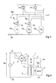
- the figure 3 represents the equivalent circuit diagram of a control device of an asynchronous motor according to an embodiment of the present invention.
- Two windings 15 and 16 of the stator, out of phase, make it possible to control the motor in one direction or in another, and a speed variation is achieved by means of bidirectional switches, for example, triacs.
- first respective ends 12 and 14 of the windings 15 and 16 of the stator of the motor 1 are each connected to the anode of a triac T'4 or T'5 of a circuit 7 selecting the direction of rotation of the motor.
- the respective triggers of triacs T'4 and T'5 are, for example, connected to output terminals 04 and 05 of a microcontroller 5 (MCU), or other control circuit capable of supplying suitable voltage signals, by resistors R74 and R75.
- the ends 12 and 14 are also connected to each other by a capacitive element C17 phase shift.
- the respective cathodes of triacs T'4 and T'5 are connected to a common reference terminal 6 of the control device.
- This terminal 6 receives a DC potential Vcc (typically the more positive potential of a DC voltage Vcc, preferably the same as that supplying the unit 5) and is connected directly to the cathodes of triacs T1, T2 and T3 of a 3 'speed selection circuit.
- Vcc typically the more positive potential of a DC voltage Vcc, preferably the same as that supplying the unit 5
- the number of triacs used for speed control has been arbitrarily set to 3. This number can be varied according to the number of different speeds desired.
- the respective anodes of triacs T1, T2 and T3 are connected to a terminal 22 for applying an AC voltage Vac by cells 33 1 , 33 2 and 33 3 respectively, modifying the impedance in series with the windings.
- Each cell 33 i (i being between 1 and 3 in this example) is, for example, consisting of a parallel combination of a resistor R33 i resetting (discharging) of the cell, with a series combination of a capacitive element C33 i and a resistor R'33 i for limiting the inrush current.
- the respective triggers of the triacs T1, T2 and T3 are connected to output terminals O1, O2 and O3 of the microcontroller 5 by voltage-current conversion resistors R36 1 , R36 2 and R36 3 .
- Second respective ends 11 and 13 of the two windings 15 and 16 of the motor stator are connected together at another terminal 21 for applying the alternating voltage Vac.
- the motor supply current passes through one or the other of the windings 15 or 16 of the stator, which determines the speed of rotation of the motor .
- resistors (R34 i , figure 2 ) and capacitors (C34 i , figure 2 ) not shown in figure 3 can be provided in parallel with each triac T1, T2, T3 to limit the voltage fronts at the opening.
- Resistors (R35 i , figure 2 ) imposing a potential difference between cathode and trigger triacs Ti may also be provided.
- the figure 4 represents the partial electrical diagram of an alternative embodiment.
- One of the cells 33i (in this example, the cell 33 1 ) is omitted, the corresponding triac Ti then serving to control the motor in its maximum speed of rotation.
- resistors R34i and capacitors C34 i are provided in the circuit, they are not for the triac (T1) whose anode is directly connected to the terminal 22.
- the impedances Z i conditioning the other rotational speeds have been symbolized by blocks 33 i .
- the other elements of the device are similar to those described in relation to the figure 3 .
- the figure 5 represents the partial electrical diagram of another variant.
- One of the triacs Ti (for example the triac T3, figure 3 ) is replaced by a short circuit, the corresponding cell 33 i being maintained and setting a default speed of rotation of the motor. This speed is then adapted, for example, by the other two branches of triacs.
- Variants of figures 4 and 5 can be combined (absence of block cell 33 1 symbolized by a dotted block in figure 5 ).
- the figure 6 represents, very schematically and in block form, the functional architecture of the device of the figure 3 .
- a common reference point 6 is provided between a first circuit 7 (DIR) with bidirectional switches for selecting the direction of rotation of the motor and a second circuit 3 '(SPEED) with bidirectional switches for controlling the speed of rotation of the motor.
- the circuits 7 and 3 ' are therefore connected in series.
- the circuit 7 is controlled by two low voltage signals (link 56) from a control unit 5 (MCU) while the circuit 3 'is controlled by n signals from the unit 5 as a function of the number of possible speeds.
- Point 6 is connected to a DC potential Vcc.
- the bidirectional switches of the sense selection circuit and the speed selection circuit are therefore in series with their interconnected cathodes.
- An advantage of the present invention is that the outputs of the control unit can be uniform. Moreover, the integration of the device is facilitated by the common cathode structure.
- Another advantage of the present invention is that it avoids the consumption of the coil of a relay.
- the lack of electromagnetic control relays reduces noise and electromagnetic noise.
- control circuit of the invention Possible applications include fan motors, washing machine or tumble dryer motors, air conditioning fan motors, vacuum pump motors, and the like. vacuum cleaner, etc.
- variable element for example a variable resistor or capacitor
- the invention more particularly applies to a speed selection between discrete values
- control signals of the different bidirectional switches for example by a microcontroller, uses tools within the reach of those skilled in the art.
Landscapes
- Engineering & Computer Science (AREA)
- Power Engineering (AREA)
- Control Of Ac Motors In General (AREA)
- Control Of Electric Motors In General (AREA)
- Lock And Its Accessories (AREA)
- Steering Control In Accordance With Driving Conditions (AREA)
- Vending Machines For Individual Products (AREA)
Claims (10)
- Vorrichtung zum Steuern der Geschwindigkeit und der Richtung einer Rotation eines asynchronen Motors (1), dadurch gekennzeichnet, dass sie Folgendes aufweist:einen ersten Schaltkreis (7) mit zwei individuell steuerbaren bidirektionalen Schaltern (T'4, T'5) mit ersten Kontaktieranschlüssen, die mit einem gemeinsamen Anschluss (6) zum Anlegen einer Gleichspannung (Vcc) und mit zweiten Kontaktieranschlüssen, die geeignet sind jeweils mit ersten Enden (12, 14) von Windungen (15, 16) des Stators des Motors verbunden zu werden; undeinen zweiten Schaltkreis (3') mit wenigstens zwei individuell steuerbaren bidirektionalen Schaltern (T1, T2, T3), die parallel sind, mit jeweils ersten Kontaktieranschlüssen (Ki), die mit dem gemeinsamen Anschluss verbunden sind, wobei der erste und der zweite Schaltkreis in Reihe geschaltet sind.
- Vorrichtung gemäß Anspruch 1, wobei bei einem der bidirektionalen Schalter (T1) des zweiten Schaltkreises der zweite Kontaktieranschluss (A1) direkt mit einem Anschluss (22) zum Anlegen einer Wechselpannung (Vac) verbunden ist, wobei bei den anderen bidirektionalen Schaltern (T2, T3) des zweiten Schaltkreises ihre jeweiligen zweiten Kontaktieranschlüsse (A2, A3) über eine Impedanz (332, 333) mit dem Anschluss zum Anlegen der Wechselspannung verbunden sind.
- Vorrichtung gemäß Anspruch 1, wobei bei den bidirektionalen Schaltern (T1, T2, T3) des zweiten Schaltkreises (3') ihre jeweiligen zweiten Kontaktieranschlüsse (Ai) über eine Impedanz (33i) mit einem Anschluss (22) zum Anlegen der Wechselspannung (Vac) verbunden sind.
- Vorrichtung gemäß Anspruch 2 oder 3, wobei die Anzahl der bidirektionalen Schalter (T1, T2) des zweiten Schaltkreises gleich der Anzahl der Rotationsgeschwindigkeiten minus 1 ist, die für den Motor gewünscht ist, wobei eine Impedanz (333) den gemeinsamen Anschluss (6) direkt mit dem Anschluss (22) zum Anlegen der Wechselspannung (Vac) verbindet.
- Vorrichtung gemäß Anspruch 2 oder 3, wobei die Anzahl der bidirektionalen Schalter (T1, T2, T3) des zweiten Schaltkreises (3') gleich der Anzahl der Rotationsgeschwindigkeiten ist, die für den Motor (1) gewünscht ist.
- Vorrichtung gemäß einem der Ansprüche 2 bis 5, wobei jeweilige zweite Enden (11, 13) der Windungen des Motors (1) geeignet sind gemeinsam mit einem weiteren Anschluss (21) zum Anlegen der Wechselspannung (Vac) verbunden zu werden, wobei ein kapazitives Element (C17) deren jeweilige erste Enden verbindet.
- Vorrichtung gemäß einem der Ansprüche 2 bis 6, wobei jede Impedanz (33i) wenigstens ein kapazitives Element (C33i) aufweist, das parallel zu einem ohmschen Element (R'33i) ist.
- Vorrichtung gemäß einem der Ansprüche 1 bis 7, wobei die bidirektionalen Schalter TRIACs (T1, T2, T3, T'4, T'5) sind, wobei deren Kathoden (Ki) mit dem gemeinsamen Anschluss (6) direkt verbunden sind.
- Vorrichtung gemäß einem der Ansprüche 1 bis 8, wobei jeweilige Steueranschlüsse der bidirektionalen Schalter (T1, T2, T3, T'4, T'5) geeignet sind mit Ausgangsanschlüssen (0) eines Steuerschaltkreises (5) verbunden zu sein, der Signale mit zwei Zuständen bereitstellt.
- Vorrichtung, die einen asynchronen Motor (1), der geeignet ist durch eine Wechselspannung (Vac) angetrieben zu werden, und die Steuervorrichtung (3', 5, 7) nach einem der Ansprüche 1 bis 9, aufweist, wobei jeweilige erste Enden (12, 14) der Windungen (15, 16) des Stators des Motors mit jeweiligen ersten Kontaktieranschlüssen des ersten Schaltkreises (7) verbunden sind.
Applications Claiming Priority (2)
| Application Number | Priority Date | Filing Date | Title |
|---|---|---|---|
| FR0752532 | 2007-01-05 | ||
| PCT/FR2008/050010 WO2008096090A1 (fr) | 2007-01-05 | 2008-01-04 | Commande d'un moteur asynchrone |
Publications (2)
| Publication Number | Publication Date |
|---|---|
| EP2097971A1 EP2097971A1 (de) | 2009-09-09 |
| EP2097971B1 true EP2097971B1 (de) | 2010-09-01 |
Family
ID=38370941
Family Applications (1)
| Application Number | Title | Priority Date | Filing Date |
|---|---|---|---|
| EP08750465A Not-in-force EP2097971B1 (de) | 2007-01-05 | 2008-01-04 | Asynchronmotor-steuerung |
Country Status (6)
| Country | Link |
|---|---|
| US (1) | US20110006721A1 (de) |
| EP (1) | EP2097971B1 (de) |
| CN (1) | CN101617463B (de) |
| AT (1) | ATE480037T1 (de) |
| DE (1) | DE602008002401D1 (de) |
| WO (1) | WO2008096090A1 (de) |
Families Citing this family (3)
| Publication number | Priority date | Publication date | Assignee | Title |
|---|---|---|---|---|
| US20110232318A1 (en) * | 2010-03-24 | 2011-09-29 | Molon Motor And Coil Corporation | Motor with Three-In-One Operation |
| CN102780429B (zh) * | 2011-05-10 | 2016-01-20 | 台达电子工业股份有限公司 | 交流驱动马达 |
| CN107465368B (zh) * | 2016-05-30 | 2023-09-26 | 德昌电机(深圳)有限公司 | 电机及其驱动电路与驱动方法 |
Family Cites Families (16)
| Publication number | Priority date | Publication date | Assignee | Title |
|---|---|---|---|---|
| US3529221A (en) * | 1968-08-08 | 1970-09-15 | Herbert J Reinke | Solid state starting circuit for electric motors |
| US4065804A (en) * | 1974-07-29 | 1977-12-27 | Rostad Rolf A | Electronic control system for motors and the like |
| JP3041123B2 (ja) | 1992-02-14 | 2000-05-15 | 株式会社東芝 | 洗濯機 |
| JP3126514B2 (ja) * | 1992-09-14 | 2001-01-22 | 株式会社東芝 | 洗濯機 |
| JP2794387B2 (ja) | 1994-01-24 | 1998-09-03 | 日本サーボ株式会社 | 制御装置を備える単相誘導電動機 |
| US5483139A (en) * | 1994-03-14 | 1996-01-09 | General Electric Company | Motor start, reverse and protection system without a starting capacitor |
| AU7616096A (en) * | 1995-11-30 | 1997-06-19 | William Harry Kemp | Current modulation motor controller |
| US6160372A (en) * | 1997-07-14 | 2000-12-12 | Robertshaw Controls Company | Solid state motor start method and apparatus |
| ITTO980027A1 (it) * | 1998-01-15 | 1999-07-15 | Plaset Srl | Circuito di pilotaggio per un motore elettrico sincrono in corrente al ternata. |
| IT1307378B1 (it) * | 1999-08-06 | 2001-11-06 | Askoll Holding Srl | Dispositivo elettronico di alimentazione di un motore sincrono conrotore a magneti permanenti a due coppie di poli. |
| US6346790B1 (en) * | 2000-04-12 | 2002-02-12 | Emerson Electric Co. | Induction motor system with an induction motor and an electrically isolated voltage modulation motor controller |
| US20030213371A1 (en) * | 2002-05-14 | 2003-11-20 | Saunders David N. | Conveyor-toaster control system |
| JP4097034B2 (ja) * | 2004-02-24 | 2008-06-04 | 株式会社センサータ・テクノロジーズジャパン | 省電力化モータ起動装置 |
| JP3846599B2 (ja) * | 2005-08-08 | 2006-11-15 | 三菱電機株式会社 | モータ制御装置、及び洗濯機 |
| CN1917729A (zh) * | 2005-08-16 | 2007-02-21 | 法洛斯创新公司 | 可变效果照明系统 |
| FR2893781A1 (fr) * | 2005-11-23 | 2007-05-25 | St Microelectronics Sa | Commande d'un triac pour demarrage d'un moteur |
-
2008
- 2008-01-04 WO PCT/FR2008/050010 patent/WO2008096090A1/fr not_active Ceased
- 2008-01-04 EP EP08750465A patent/EP2097971B1/de not_active Not-in-force
- 2008-01-04 US US12/521,808 patent/US20110006721A1/en not_active Abandoned
- 2008-01-04 CN CN2008800009028A patent/CN101617463B/zh not_active Expired - Fee Related
- 2008-01-04 DE DE602008002401T patent/DE602008002401D1/de active Active
- 2008-01-04 AT AT08750465T patent/ATE480037T1/de not_active IP Right Cessation
Also Published As
| Publication number | Publication date |
|---|---|
| CN101617463B (zh) | 2012-11-14 |
| ATE480037T1 (de) | 2010-09-15 |
| WO2008096090A1 (fr) | 2008-08-14 |
| CN101617463A (zh) | 2009-12-30 |
| EP2097971A1 (de) | 2009-09-09 |
| DE602008002401D1 (de) | 2010-10-14 |
| US20110006721A1 (en) | 2011-01-13 |
Similar Documents
| Publication | Publication Date | Title |
|---|---|---|
| WO2013056918A1 (fr) | Convertisseur de puissance et son circuit de pre-charge | |
| EP1005161B1 (de) | Steuerungsschaltung für einen Halbleiterschalter im Wechselbetrieb | |
| EP2097971A1 (de) | Asynchrone motorsteuerung | |
| FR2803958A1 (fr) | Moteur a commutation electronique | |
| FR2714234A1 (fr) | Système de contrôle d'alimentation d'un moteur asynchrone. | |
| EP1646132A2 (de) | Doppelte Versorgungsschaltung | |
| EP3657677A1 (de) | Stromversorgungsschaltkreis für steuerschaltungen von schaltern | |
| US5703458A (en) | Capacitor-type motor speed controller | |
| EP2179501B1 (de) | Einrichtung zur versorgung eines hausautomatisierungsstellgliedes und betriebsverfahren der einrichtung | |
| JP2009542179A5 (de) | ||
| FR2613551A1 (fr) | Dispositif automatique de correction de l'ordre de succession des phases de l'alimentation triphasee d'une installation electrique | |
| EP3726731B1 (de) | Steuerschaltkreis von transistoren | |
| EP2823562A1 (de) | Verfahren zur steuerung einer leistungsbrücke und zugehörige steuerungsvorrichtung, leistungsbrücke und elektrische drehmaschine | |
| EP0670628B1 (de) | Stromversorgungsvorrichtung für einen Wechselstrommotor | |
| NL1003816C2 (nl) | Vermogensregelaar, in het bijzonder voor éénfase-wisselstroommotoren, zoals ventilatormotoren, voor resistieve verwarmingsweerstanden of dergelijke. | |
| US4128791A (en) | Phase shift circuit for synchronous motor | |
| FR2998115A1 (fr) | Etage de conversion, convertisseur electrique comportant un tel etage de conversion, dispositif de conversion d'un courant alternatif en un courant continu comportant un tel convertisseur, et borne de rechargement d'une batterie electrique comportant un tel convertisseur ou dispositif de conversion | |
| EP3195466B1 (de) | Verfahren zur steuerung einer umrichtervorrichtung und zugehörige steuerungsvorrichtung | |
| EP2675058B1 (de) | Versorgungskreislauf eines Asynchronmotors | |
| EP1730837B1 (de) | Steuereinrichtung für einen rolladenantriebsmotor | |
| FR2543378A1 (fr) | Dispositif pour alimenter un moteur a courant continu au moyen d'un courant alternatif redresse, avec protection contre les surintensites | |
| EP0911957B1 (de) | Einphasen Asynchronmotor mit zwei Windungen | |
| CA2178026C (en) | Capacitor-type motor speed controller | |
| FR2550027A1 (fr) | Circuit de commande en angle de phase de triac sur charge inductive | |
| EP1444768A2 (de) | Verfahren und einrichtung zur transformation einer gleichspannung und verwendung der einrichtung |
Legal Events
| Date | Code | Title | Description |
|---|---|---|---|
| PUAI | Public reference made under article 153(3) epc to a published international application that has entered the european phase |
Free format text: ORIGINAL CODE: 0009012 |
|
| 17P | Request for examination filed |
Effective date: 20090619 |
|
| AK | Designated contracting states |
Kind code of ref document: A1 Designated state(s): AT BE BG CH CY CZ DE DK EE ES FI FR GB GR HR HU IE IS IT LI LT LU LV MC MT NL NO PL PT RO SE SI SK TR |
|
| 17Q | First examination report despatched |
Effective date: 20091015 |
|
| GRAP | Despatch of communication of intention to grant a patent |
Free format text: ORIGINAL CODE: EPIDOSNIGR1 |
|
| DAX | Request for extension of the european patent (deleted) | ||
| GRAS | Grant fee paid |
Free format text: ORIGINAL CODE: EPIDOSNIGR3 |
|
| GRAA | (expected) grant |
Free format text: ORIGINAL CODE: 0009210 |
|
| AK | Designated contracting states |
Kind code of ref document: B1 Designated state(s): AT BE BG CH CY CZ DE DK EE ES FI FR GB GR HR HU IE IS IT LI LT LU LV MC MT NL NO PL PT RO SE SI SK TR |
|
| REG | Reference to a national code |
Ref country code: GB Ref legal event code: FG4D Free format text: NOT ENGLISH |
|
| REG | Reference to a national code |
Ref country code: CH Ref legal event code: EP |
|
| REG | Reference to a national code |
Ref country code: IE Ref legal event code: FG4D Free format text: LANGUAGE OF EP DOCUMENT: FRENCH |
|
| REF | Corresponds to: |
Ref document number: 602008002401 Country of ref document: DE Date of ref document: 20101014 Kind code of ref document: P |
|
| REG | Reference to a national code |
Ref country code: NL Ref legal event code: VDEP Effective date: 20100901 |
|
| PG25 | Lapsed in a contracting state [announced via postgrant information from national office to epo] |
Ref country code: AT Free format text: LAPSE BECAUSE OF FAILURE TO SUBMIT A TRANSLATION OF THE DESCRIPTION OR TO PAY THE FEE WITHIN THE PRESCRIBED TIME-LIMIT Effective date: 20100901 Ref country code: LT Free format text: LAPSE BECAUSE OF FAILURE TO SUBMIT A TRANSLATION OF THE DESCRIPTION OR TO PAY THE FEE WITHIN THE PRESCRIBED TIME-LIMIT Effective date: 20100901 Ref country code: NO Free format text: LAPSE BECAUSE OF FAILURE TO SUBMIT A TRANSLATION OF THE DESCRIPTION OR TO PAY THE FEE WITHIN THE PRESCRIBED TIME-LIMIT Effective date: 20101201 Ref country code: FI Free format text: LAPSE BECAUSE OF FAILURE TO SUBMIT A TRANSLATION OF THE DESCRIPTION OR TO PAY THE FEE WITHIN THE PRESCRIBED TIME-LIMIT Effective date: 20100901 |
|
| LTIE | Lt: invalidation of european patent or patent extension |
Effective date: 20100901 |
|
| PG25 | Lapsed in a contracting state [announced via postgrant information from national office to epo] |
Ref country code: SI Free format text: LAPSE BECAUSE OF FAILURE TO SUBMIT A TRANSLATION OF THE DESCRIPTION OR TO PAY THE FEE WITHIN THE PRESCRIBED TIME-LIMIT Effective date: 20100901 Ref country code: PL Free format text: LAPSE BECAUSE OF FAILURE TO SUBMIT A TRANSLATION OF THE DESCRIPTION OR TO PAY THE FEE WITHIN THE PRESCRIBED TIME-LIMIT Effective date: 20100901 Ref country code: HR Free format text: LAPSE BECAUSE OF FAILURE TO SUBMIT A TRANSLATION OF THE DESCRIPTION OR TO PAY THE FEE WITHIN THE PRESCRIBED TIME-LIMIT Effective date: 20100901 Ref country code: CY Free format text: LAPSE BECAUSE OF FAILURE TO SUBMIT A TRANSLATION OF THE DESCRIPTION OR TO PAY THE FEE WITHIN THE PRESCRIBED TIME-LIMIT Effective date: 20100901 |
|
| REG | Reference to a national code |
Ref country code: IE Ref legal event code: FD4D |
|
| PG25 | Lapsed in a contracting state [announced via postgrant information from national office to epo] |
Ref country code: NL Free format text: LAPSE BECAUSE OF FAILURE TO SUBMIT A TRANSLATION OF THE DESCRIPTION OR TO PAY THE FEE WITHIN THE PRESCRIBED TIME-LIMIT Effective date: 20100901 Ref country code: GR Free format text: LAPSE BECAUSE OF FAILURE TO SUBMIT A TRANSLATION OF THE DESCRIPTION OR TO PAY THE FEE WITHIN THE PRESCRIBED TIME-LIMIT Effective date: 20101202 Ref country code: LV Free format text: LAPSE BECAUSE OF FAILURE TO SUBMIT A TRANSLATION OF THE DESCRIPTION OR TO PAY THE FEE WITHIN THE PRESCRIBED TIME-LIMIT Effective date: 20100901 Ref country code: SE Free format text: LAPSE BECAUSE OF FAILURE TO SUBMIT A TRANSLATION OF THE DESCRIPTION OR TO PAY THE FEE WITHIN THE PRESCRIBED TIME-LIMIT Effective date: 20100901 |
|
| PG25 | Lapsed in a contracting state [announced via postgrant information from national office to epo] |
Ref country code: IE Free format text: LAPSE BECAUSE OF FAILURE TO SUBMIT A TRANSLATION OF THE DESCRIPTION OR TO PAY THE FEE WITHIN THE PRESCRIBED TIME-LIMIT Effective date: 20100901 |
|
| PG25 | Lapsed in a contracting state [announced via postgrant information from national office to epo] |
Ref country code: IS Free format text: LAPSE BECAUSE OF FAILURE TO SUBMIT A TRANSLATION OF THE DESCRIPTION OR TO PAY THE FEE WITHIN THE PRESCRIBED TIME-LIMIT Effective date: 20110101 Ref country code: CZ Free format text: LAPSE BECAUSE OF FAILURE TO SUBMIT A TRANSLATION OF THE DESCRIPTION OR TO PAY THE FEE WITHIN THE PRESCRIBED TIME-LIMIT Effective date: 20100901 Ref country code: RO Free format text: LAPSE BECAUSE OF FAILURE TO SUBMIT A TRANSLATION OF THE DESCRIPTION OR TO PAY THE FEE WITHIN THE PRESCRIBED TIME-LIMIT Effective date: 20100901 Ref country code: EE Free format text: LAPSE BECAUSE OF FAILURE TO SUBMIT A TRANSLATION OF THE DESCRIPTION OR TO PAY THE FEE WITHIN THE PRESCRIBED TIME-LIMIT Effective date: 20100901 Ref country code: SK Free format text: LAPSE BECAUSE OF FAILURE TO SUBMIT A TRANSLATION OF THE DESCRIPTION OR TO PAY THE FEE WITHIN THE PRESCRIBED TIME-LIMIT Effective date: 20100901 Ref country code: PT Free format text: LAPSE BECAUSE OF FAILURE TO SUBMIT A TRANSLATION OF THE DESCRIPTION OR TO PAY THE FEE WITHIN THE PRESCRIBED TIME-LIMIT Effective date: 20110103 |
|
| PG25 | Lapsed in a contracting state [announced via postgrant information from national office to epo] |
Ref country code: ES Free format text: LAPSE BECAUSE OF FAILURE TO SUBMIT A TRANSLATION OF THE DESCRIPTION OR TO PAY THE FEE WITHIN THE PRESCRIBED TIME-LIMIT Effective date: 20101212 |
|
| PLBE | No opposition filed within time limit |
Free format text: ORIGINAL CODE: 0009261 |
|
| STAA | Information on the status of an ep patent application or granted ep patent |
Free format text: STATUS: NO OPPOSITION FILED WITHIN TIME LIMIT |
|
| BERE | Be: lapsed |
Owner name: STMICROELECTRONICS SA Effective date: 20110131 |
|
| 26N | No opposition filed |
Effective date: 20110606 |
|
| PG25 | Lapsed in a contracting state [announced via postgrant information from national office to epo] |
Ref country code: DK Free format text: LAPSE BECAUSE OF FAILURE TO SUBMIT A TRANSLATION OF THE DESCRIPTION OR TO PAY THE FEE WITHIN THE PRESCRIBED TIME-LIMIT Effective date: 20100901 Ref country code: MC Free format text: LAPSE BECAUSE OF NON-PAYMENT OF DUE FEES Effective date: 20110131 |
|
| REG | Reference to a national code |
Ref country code: DE Ref legal event code: R097 Ref document number: 602008002401 Country of ref document: DE Effective date: 20110606 |
|
| PG25 | Lapsed in a contracting state [announced via postgrant information from national office to epo] |
Ref country code: BE Free format text: LAPSE BECAUSE OF NON-PAYMENT OF DUE FEES Effective date: 20110131 |
|
| PG25 | Lapsed in a contracting state [announced via postgrant information from national office to epo] |
Ref country code: MT Free format text: LAPSE BECAUSE OF FAILURE TO SUBMIT A TRANSLATION OF THE DESCRIPTION OR TO PAY THE FEE WITHIN THE PRESCRIBED TIME-LIMIT Effective date: 20100901 |
|
| REG | Reference to a national code |
Ref country code: CH Ref legal event code: PL |
|
| PG25 | Lapsed in a contracting state [announced via postgrant information from national office to epo] |
Ref country code: LI Free format text: LAPSE BECAUSE OF NON-PAYMENT OF DUE FEES Effective date: 20120131 Ref country code: CH Free format text: LAPSE BECAUSE OF NON-PAYMENT OF DUE FEES Effective date: 20120131 |
|
| PG25 | Lapsed in a contracting state [announced via postgrant information from national office to epo] |
Ref country code: LU Free format text: LAPSE BECAUSE OF NON-PAYMENT OF DUE FEES Effective date: 20110104 |
|
| PG25 | Lapsed in a contracting state [announced via postgrant information from national office to epo] |
Ref country code: TR Free format text: LAPSE BECAUSE OF FAILURE TO SUBMIT A TRANSLATION OF THE DESCRIPTION OR TO PAY THE FEE WITHIN THE PRESCRIBED TIME-LIMIT Effective date: 20100901 Ref country code: BG Free format text: LAPSE BECAUSE OF FAILURE TO SUBMIT A TRANSLATION OF THE DESCRIPTION OR TO PAY THE FEE WITHIN THE PRESCRIBED TIME-LIMIT Effective date: 20101201 |
|
| PG25 | Lapsed in a contracting state [announced via postgrant information from national office to epo] |
Ref country code: HU Free format text: LAPSE BECAUSE OF FAILURE TO SUBMIT A TRANSLATION OF THE DESCRIPTION OR TO PAY THE FEE WITHIN THE PRESCRIBED TIME-LIMIT Effective date: 20100901 |
|
| PGFP | Annual fee paid to national office [announced via postgrant information from national office to epo] |
Ref country code: GB Payment date: 20131223 Year of fee payment: 7 |
|
| PGFP | Annual fee paid to national office [announced via postgrant information from national office to epo] |
Ref country code: DE Payment date: 20131219 Year of fee payment: 7 |
|
| PGFP | Annual fee paid to national office [announced via postgrant information from national office to epo] |
Ref country code: IT Payment date: 20131219 Year of fee payment: 7 Ref country code: FR Payment date: 20140120 Year of fee payment: 7 |
|
| REG | Reference to a national code |
Ref country code: DE Ref legal event code: R119 Ref document number: 602008002401 Country of ref document: DE |
|
| GBPC | Gb: european patent ceased through non-payment of renewal fee |
Effective date: 20150104 |
|
| PG25 | Lapsed in a contracting state [announced via postgrant information from national office to epo] |
Ref country code: GB Free format text: LAPSE BECAUSE OF NON-PAYMENT OF DUE FEES Effective date: 20150104 Ref country code: DE Free format text: LAPSE BECAUSE OF NON-PAYMENT OF DUE FEES Effective date: 20150801 |
|
| REG | Reference to a national code |
Ref country code: FR Ref legal event code: ST Effective date: 20150930 |
|
| PG25 | Lapsed in a contracting state [announced via postgrant information from national office to epo] |
Ref country code: FR Free format text: LAPSE BECAUSE OF NON-PAYMENT OF DUE FEES Effective date: 20150202 |
|
| PG25 | Lapsed in a contracting state [announced via postgrant information from national office to epo] |
Ref country code: IT Free format text: LAPSE BECAUSE OF NON-PAYMENT OF DUE FEES Effective date: 20150104 |