EP2098105B1 - Mittels natürlicher und zwangsbelüftung gekühltes gehäuse eines elektronischen geräts - Google Patents
Mittels natürlicher und zwangsbelüftung gekühltes gehäuse eines elektronischen geräts Download PDFInfo
- Publication number
- EP2098105B1 EP2098105B1 EP07857387A EP07857387A EP2098105B1 EP 2098105 B1 EP2098105 B1 EP 2098105B1 EP 07857387 A EP07857387 A EP 07857387A EP 07857387 A EP07857387 A EP 07857387A EP 2098105 B1 EP2098105 B1 EP 2098105B1
- Authority
- EP
- European Patent Office
- Prior art keywords
- thermal
- radiators
- bay
- external
- housing according
- Prior art date
- Legal status (The legal status is an assumption and is not a legal conclusion. Google has not performed a legal analysis and makes no representation as to the accuracy of the status listed.)
- Not-in-force
Links
Images


Classifications
-
- H—ELECTRICITY
- H05—ELECTRIC TECHNIQUES NOT OTHERWISE PROVIDED FOR
- H05K—PRINTED CIRCUITS; CASINGS OR CONSTRUCTIONAL DETAILS OF ELECTRIC APPARATUS; MANUFACTURE OF ASSEMBLAGES OF ELECTRICAL COMPONENTS
- H05K7/00—Constructional details common to different types of electric apparatus
- H05K7/20—Modifications to facilitate cooling, ventilating, or heating
- H05K7/20536—Modifications to facilitate cooling, ventilating, or heating for racks or cabinets of standardised dimensions, e.g. electronic racks for aircraft or telecommunication equipment
- H05K7/20663—Liquid coolant with phase change, e.g. heat pipes
- H05K7/20672—Liquid coolant with phase change, e.g. heat pipes within sub-racks for removing heat from electronic boards
Definitions
- the invention relates to the cooling of electronic equipment housed in housings or bays placed on reception platforms having a forced circulation of cooling air that may be prone to malfunctions. It relates in particular, enclosures or bays of electronic equipment embedded on board aircraft.
- the cooling of a boxed electronic equipment is usually obtained by evacuating the calories produced inside the housing to the outside environment by means of a possibly pulsed air flow, penetrating into the housing through ventilation holes located in the lower part serving as mouths, coming into contact with the components of the electronic equipment and evacuating in the upper part of the housing through ventilation holes serving as vents.
- the possibilities of evacuation of calories increase with the flow of cooling air.
- the diameter and the number of ventilation openings are constrained to meet a pressure drop for a standard air flow, itself a function of the power dissipated. This constraint makes it possible to distribute the flow of pulsed air between the different computers.
- Electronic equipment intended to be onboard aircraft is usually placed in housings provided with ventilation holes of a diameter and a sufficient number to allow normal cooling by natural convection alone. These boxes are placed on a box of distribution of pulsed air, a sort of organ bed base, distributing them, through their ventilation holes, a flow of air cooling under pressure to precise specifications, for example those appearing in the standard ARINC 600 relating to the configuration of the housings and chassis used in the aircraft to house equipment replaceable electronics also known as "rack-mountable".
- the cooling is only ensured by a natural convection which is not very effective because of the too small useful section of the ventilation holes limited in diameter and in number: in diameter by the requirements of the electromagnetic shielding and in number by the pressure drop imposed by the standard, as well as due to the volume of outside air available under the housings reduces to the capacity of the forced air distribution box.
- the equipment temperature then increases significantly, which degrades their temperature operating margin.
- Controlling the operating temperature of an electronic equipment in the event of loss of the forced air flow is the main limitation encountered when one seeks to reduce its bulk and to increase its functionalities by a densification of the electronics because both are always accompanied by an increase in the production of calories per liter.
- the present invention aims to improve natural convection cooling, an electronic equipment housing in the presence of limitation in diameter and number of opportunities for drilling natural ventilation holes in its walls, with benefit of a possible forced ventilation provided by internal ramps of forced air distribution.
- an electronic equipment box cooled by natural ventilation, by the presence of ventilation holes in the walls of the housing and forced ventilation, by forced air comprising at least one internal thermal radiator cooled by natural ventilation and forced in thermal contact with one or more hot spots of an electrical equipment placed in the housing, characterized in that the internal heat radiator is placed in thermal contact with the hot spot (s) via at least one heat sink. heat connected to at least one thermal conductor passing through walls of the housing and terminating at one or more external heat radiators.
- the internal heat radiator or radiators are sized to be sufficient to cool the electrical equipment placed in the housing in the event of normal operation of the forced ventilation while and the external heat radiator or radiators are sized to complete the cooling provided by the internal heat radiators in case of loss of forced ventilation.
- a part of the air flow of the forced ventilation is directed on the external heat radiator or radiators.
- the forced ventilation is provided by means of internal ramps for distributing pulsed air passing through the walls of the housing and reaching the level of the external heat radiator or radiators.
- the electronic equipment box comprises flat removable modules arranged in a bay, side by side, on the edge, according to one or more alignments perpendicular to the bottom of the bay, the external heat radiator or radiators are fixed to the outside, on the front slices of modules facing the front of the bay.
- the forced ventilation of an external heat radiator fixed to the edge of a module is obtained by means of a pulsed air distribution manifold inside the module extending through the front edge of the module.
- the electronic equipment box comprises flat removable modules arranged in a bay, side by side, on the edge, according to one or more alignments perpendicular to the bottom of the bay, the external heat radiator or radiators are placed in one or chimneys with natural and forced ventilation, fixed on the outside, on the front slices of the modules facing the front of the bay.
- the forced ventilation of a chimney is obtained by means of a pulsed air distribution ramp inside the module extending through the front edge of the module towards the base of the chimney.
- the natural draft of a chimney is amplified by a Venturi effect obtained by means of forced ventilation.
- the forced ventilation of a chimney is obtained by means of a pulsed air distribution manifold inside the housing extending through the wall of the housing by a Venturi effect nozzle penetrating into the base of the chimney. chimney and delivering a flow of pulsed air amplifying the natural circulation of the air within the chimney.
- the natural ventilation of a chimney is amplified by an auxiliary fan placed at the base of the chimney, against a partition isolating it from the air flow of the forced ventilation introduced into the chimney.
- the natural ventilation of a chimney is amplified by a supplementary fan operating in case of exceeding a set temperature by the external heat radiator or radiators housed in the chimney.
- the thermal conductor or conductors are heat pipes.
- the thermal conductor or conductors are carbon-based rods with high thermal conductivity in the longitudinal direction.
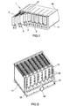
- the electronic rack 1 which will be described is intended to contain a set of electronic modules 2, 3, 4 said rackable as plug in a frame 5 of the rack 1 in the manner of drawers.
- the electronic rack modules 2, 3, 4 are rectangular rather flat. They comprise a frame-frame 6 supporting a printed circuit board 7 with visible longitudinal edges constituting longitudinal guide edges 8, 9, and two metal covers 10, 11 providing physical and electromagnetic protection of the printed circuit board 7 and of its components.
- the metal covers may consist of printed circuit boards whose ground planes serve as shielding.
- the electronic modules 2, 3, 4 may have other conformations provided that they comply with the dimensional constraints imposed by the rack 1.
- their longitudinal guide edges 8, 9 can be offset on the internal radiators 12, 13 , 14 fins in thermal contact with the components releasing calories, to evacuate a portion of the calories in the frame of the bay 1 or on one of the covers 10, 11.
- the electronic rack 1 is provided with a metal frame 5 having, in the usual manner, side walls 17, a bottom wall not visible in the figures, an upper wall 18 and a rear wall 19.
- the lower and upper walls 18 of the bay 1 support, opposite, two networks of parallel slides oriented perpendicularly to the rear wall 19 and used for guiding the longitudinal edges 8, 9 of the rack modules 2, 3, 4 during the introducing, extracting and holding in place modules 2, 3, 4 side by side, on the edge, their printed circuit boards 7 oriented in vertical planes perpendicular to the rear wall 19 of the bay 1.
- the rear wall 19 of the rack 1 supports, in its upper part, a set 20 of backplane connectors fitting with the connector assembly or sets 15, 16 of the printed circuit boards 7 of the modules 2, 3, 4 to ensure the connections of the modules 2, 3, 4 to each other and to the environment outside the bay 1.
- the fins of the internal heat radiators 12, 13, 14 of the various modules 2, 3, 4 are oriented perpendicularly to the longitudinal edges of the modules 2, 3, 4 so as to be in a vertical position once the modules 2, 3, 4 in place in the bay 1 and facilitate their scans by ascending currents of cooling air obtained by natural convection and by forced circulation.
- the ventilation holes 21 made in the lower and upper walls 18 of the bay 1 consist of holes of small diameter, of the order of 3 millimeters compatible with the requirements of an electromagnetic shielding of the bay 1.
- Those practiced in a intermediate wall, lower or upper, designed to separate two stages of modules, are wide longitudinal slots because the continuity of the electromagnetic shielding of the bay 1 is not provided at this level but that of the bottom or the cover of the bay 1 .
- the fins of the internal heat radiators of the modules 2, 3, 4 are subjected to forced ventilation by means of ramps 30 of pulsed air distribution fed via a distribution box.
- 31 figure 5
- the pulsed air distribution ramps 30 are in the form of small "piccolo" flutes with an obstructed roof, whose play holes serve as lateral vents. They are arranged horizontally, at the base of the modules 2, 3, 4 along the internal heat radiators 12, 13, 14 with fins, perpendicular to the rear wall 19 of the bay 1, with their individual mouths 33 nested in holes distribution of pulsed air distribution box 31 accessible from inside the bay 1 through the rear wall 19, and with their side vents blowing cooling air between the fins of the internal heat radiators 12, 13, 14 of the modules 2, 3, 4.
- the pulsed air distribution ramps 30 are attached to the internal heat radiators 12, 13, 14 finned modules 2, 3, 4 in grooves cut perpendicularly to the fins, near their bases. Their side vents, not visible in the figures, are turned towards the bottoms of the slots separating the fins, with a slight upward shift to initiate and maintain updrafts.
- the pulsed air distribution manifolds 30 are spaced from the bottom of the grooves 34 so as not to obstruct the ascending air currents resulting from natural convection, an amplification, by the Venturi effect, of these ascending air currents. being even sought after by an adequate orientation of the ramp vents 30.
- the components mounted on the most calorific printed circuit board 7, for example the microprocessor chips, are brought into contact with the internal heat radiators 12, 13, 14 with fins via heat collectors 40, 41 connected to thermal conductors 42, 43, for example heat-conducting heat-conductive carbon pipes or rods in the longitudinal direction, passing through the front wall 44 of the frame-frame 6 of a module 2, 3, 4 and terminating an external heat radiator 45 placed in a chimney 46 fixed externally to the front edge of a module 2, 3, 4.
- the chimney 46 enclosing the external heat radiator 45 has its walls consisting of two half-shells 46 ', 46 "mounted on fixed collars, such as the external heat radiator 45, to the front wall 44 of the frame-frame 6.
- the base the chimney 46 rests on a support 47 of fan 48 forming an intermediate chamber 49 between it and the front wall 44 of the frame-frame 6.
- This intermediate chamber 49 opens into the base of the chimney 46 while being isolated from the fan 48.
- the forced air distribution manifold 30 providing for forced ventilation of the inner finned heat radiators 12, 13, 14, passes through the front wall of the frame frame 6 to reach the intermediate chamber 49 and to blow, at the base of the the chimney 46, by a nozzle or vent, a pulsed air stream amplifying by Venturi effect the natural air stream coming, when the fan 48 does not rotate, the space left free between the blades of the latter.
- the figure 4 illustrates the distribution of the cooling air currents resulting from natural convection and forced air distribution along the different heat radiators of a module 2, 3, 4.
- Natural convection causes a sheet of updrafts of cooling air identified by arrows 51, distributed along the fins 50 of the internal heat radiators 12, 13, 14 and an ascending air current indicated by an arrow 52, circulating in the outer chimney 46 along the fins 53 of the external heat radiator 45.
- the internal heat radiators 12, 13, 14 are sized to be sufficient for cooling the electrical equipment placed in a module 2, 3, 4 in the event of normal operation of the forced ventilation.
- the External heat radiator 45 is sized to supplement the cooling provided by the internal radiators in case of loss of forced ventilation.
- the fan 48 is triggered by a thermostat if a set temperature on the card 7 or on the components of the card 7 is exceeded.
- the ramps 30 can be detached from the fins of the internal heat radiators or frame-frame modules and have their own mounting brackets, for example clips attached to the lower wall of the bay 1 between the slides. They can even be integral with the distribution box 31. Their side vents can take various forms including those of slots.
- the chimneys containing the heat radiators external to the modules can form a unit with the fins of these radiators when they are not likely to reach dangerous temperatures for operators.
Landscapes
- Engineering & Computer Science (AREA)
- Aviation & Aerospace Engineering (AREA)
- Physics & Mathematics (AREA)
- Thermal Sciences (AREA)
- Microelectronics & Electronic Packaging (AREA)
- Cooling Or The Like Of Electrical Apparatus (AREA)
Claims (13)
- Gehäuse (1) für ein elektronisches Gerät, das durch natürliche Belüftung aufgrund der Anwesenheit von Lüftungslöchern in den Wänden des Gehäuses und durch Zwangsbelüftung mit Gebläseluft gekühlt wird, wobei das Gerät wenigstens einen durch natürliche und Zwangsbelüftung gekühlten internen Temperaturstrahler (12, 13, 14) in thermischem Kontakt mit einer oder mehreren heißen Stellen eines in dem Gehäuse (1) befindlichen elektronischen Gerätes aufweist, dadurch gekennzeichnet, dass der interne Temperaturstrahler mit Hilfe wenigstens eines Wärmekollektors (40, 41) mit den ein oder mehreren heißen Stellen in thermischen Kontakt gebracht wird, der mit wenigstens einem Wärmeleiter (42, 43) verbunden ist, der durch die Wände (44) des Gehäuses (1) verläuft und zu einem oder mehreren externen Temperaturstrahlern (45) führt.
- Gehäuse nach Anspruch 1, dadurch gekennzeichnet, dass der oder die internen Temperaturstrahler (12, 13, 14) für eine ausreichende Kühlung des in dem Gehäuse (1) befindlichen elektronischen Gerätes bei normalem Betrieb der Zwangskühlung dimensioniert ist/sind, und dadurch, dass der oder die externen Temperaturstrahler (45) zum Ergänzen der von den internen Strahlern (12, 13, 14) bereitgestellten Kühlung im Fall eines Verlusts der Zwangsbelüftung dimensioniert ist/sind.
- Gehäuse nach Anspruch 1, dadurch gekennzeichnet, dass ein Teil des Luftstroms der Zwangsbelüftung auf den oder die externen Temperaturstrahler (45) gerichtet wird.
- Gehäuse nach Anspruch 1, dadurch gekennzeichnet, dass es wenigstens einen internen Verteiler (30) zum Verteilen von durch seine Wände (44) kommender Gebläseluft zu den ein oder mehreren externen Temperaturstrahlern (45) umfasst.
- Gehäuse nach Anspruch 1, das flache herausnehmbare Module (2, 3, 4) umfasst, die in einem Rahmen (1) nebeneinander auf dem Rand stehend in einer oder mehreren lotrechten Ausrichtungen auf dem Boden (19) des Rahmens (1) angeordnet sind, dadurch gekennzeichnet, dass der oder die externe(n) Temperaturstrahler (45) auf der Außenseite an den vorderen Rändern (44) der Module befestigt sind, die zur Vorderseite des Rahmens (1) hin gedreht sind.
- Gehäuse nach Anspruch 1, das flache herausnehmbare Module (2, 3, 4) umfasst, die in einem Rahmen (1) nebeneinander auf dem Rand stehend in einer oder mehreren lotrechten Ausrichtungen am Boden (19) des Rahmens (1) angeordnet sind, dadurch gekennzeichnet, dass der oder die externe(n) Temperaturstrahler (45) in einem oder mehreren natürlichen und Zwangsbelüftungsabzugsschloten (46) platziert sind, die an der Außenseite auf den vorderen Rändern (44) der Module (2, 3, 4) befestigt sind, die zur Vorderseite des Rahmens (1) hin gedreht sind.
- Gehäuse nach Anspruch 5, dadurch gekennzeichnet, dass ein Modul (2, 3, 4) wenigstens einen internen Verteiler (30) zum Verteilen von Gebläseluft umfasst, der durch die Wand (44) des Moduls (2, 3, 4) verläuft und die Zwangsbelüftung für die verschiedenen internen (12, 13, 14) und externen (45) Temperaturstrahler bereitstellt.
- Gehäuse nach Anspruch 6, dadurch gekennzeichnet, dass ein Modul (2, 3, 4) mit einem externen Abzugsschlot (46) einen internen Verteiler (30) zum Verteilen von Gebläseluft umfasst, der durch die Wand (44) des Moduls (2, 3, 4) verläuft und die Zwangsbelüftung für die internen Temperaturstrahler (12, 13, 14) gewährleistet und den Abzug des externen Abzugsschlots (46) verstärkt.
- Gehäuse nach Anspruch 6, dadurch gekennzeichnet, dass ein Modul (2, 3, 4) mit einem externen Abzugsschlot (46) ein Zusatzgebläse (48) umfasst, das an der Basis des Abzugsschlots (46) angeordnet ist.
- Gehäuse nach Anspruch 9, dadurch gekennzeichnet, dass ein Modul (2, 3, 4) mit einem externen Abzugsschlot (46) ein Zusatzgebläse (48) umfasst, das an der Basis des Abzugsschlots (46) angeordnet ist und in dem Fall arbeitet, dass eine Solltemperatur von dem oder den im Abzugsschlot (46) aufgenommenen externen Temperaturstrahler(n) (45) überschritten wird.
- Gehäuse nach Anspruch 8, dadurch gekennzeichnet, dass ein Modul (2, 3, 4) mit einem externen Abzugsschlot (46) an der Basis des Abzugsschlots (46) ein Zusatzgebläse (48) umfasst, das durch eine Abtrennung von einer Zwischenkammer (49) getrennt wird, die mit dem Abzugsschlot (46) in Verbindung ist und in die der interne Verteiler (30) zum Verteilen von Gebläseluft mündet.
- Gehäuse nach Anspruch 1, dadurch gekennzeichnet, dass der oder die Wärmeleiter (42, 43) Wärmerohre ist/sind.
- Gehäuse nach Anspruch 1, dadurch gekennzeichnet, dass der oder die Wärmeleiter (42, 43) Kohlenstoffstäbe mit hoher Wärmeleitfähigkeit in der Längsrichtung sind.
Applications Claiming Priority (2)
| Application Number | Priority Date | Filing Date | Title |
|---|---|---|---|
| FR0611209A FR2910779A1 (fr) | 2006-12-21 | 2006-12-21 | Boitier d'appareillage electronique a refroidissement par ventilation naturelle et forcee |
| PCT/EP2007/063700 WO2008080776A1 (fr) | 2006-12-21 | 2007-12-11 | Boitier d'appareillage electronique a refroidissement par ventilation naturelle et forcee |
Publications (2)
| Publication Number | Publication Date |
|---|---|
| EP2098105A1 EP2098105A1 (de) | 2009-09-09 |
| EP2098105B1 true EP2098105B1 (de) | 2012-03-28 |
Family
ID=38542991
Family Applications (1)
| Application Number | Title | Priority Date | Filing Date |
|---|---|---|---|
| EP07857387A Not-in-force EP2098105B1 (de) | 2006-12-21 | 2007-12-11 | Mittels natürlicher und zwangsbelüftung gekühltes gehäuse eines elektronischen geräts |
Country Status (5)
| Country | Link |
|---|---|
| US (1) | US8542485B2 (de) |
| EP (1) | EP2098105B1 (de) |
| AT (1) | ATE551888T1 (de) |
| FR (1) | FR2910779A1 (de) |
| WO (1) | WO2008080776A1 (de) |
Families Citing this family (20)
| Publication number | Priority date | Publication date | Assignee | Title |
|---|---|---|---|---|
| WO2009102335A1 (en) * | 2008-02-15 | 2009-08-20 | Hewlett-Packard Development Company, L.P. | Coolant pulsing for computer system |
| EP2298051B1 (de) * | 2008-05-20 | 2012-02-01 | Semper Holdings Limited | Kühleinheit mit rackanbringung |
| FR2934905B1 (fr) * | 2008-08-05 | 2010-09-03 | Thales Sa | Dispositif de refroidissement aeraulique de calculateur "full arinc" |
| CN102098902A (zh) * | 2009-12-11 | 2011-06-15 | 华为技术有限公司 | 散热设备、通信设备的散热方法及通信设备 |
| FR2965140B1 (fr) * | 2010-09-20 | 2013-07-05 | Ece | Dispositif de protection d'un systeme electronique monte dans un rack |
| CA2819897C (en) | 2010-12-22 | 2019-02-19 | Cooper Technologies Company | Controlling airflow within an explosion-proof enclosure |
| US9553435B2 (en) | 2010-12-22 | 2017-01-24 | Cooper Technologies Company | Manifold for controlling airflow within an explosion-proof enclosure |
| US9820406B1 (en) * | 2011-03-11 | 2017-11-14 | Lex Products Corporation | Power management and distribution system and method |
| CN102722230A (zh) * | 2011-03-29 | 2012-10-10 | 唐兵 | 一种电脑电源 |
| CN102892270B (zh) * | 2012-09-24 | 2015-05-13 | 西安电子工程研究所 | 一种多通道复合散热密封机箱 |
| US9578781B2 (en) * | 2014-05-09 | 2017-02-21 | Advanced Cooling Technologies, Inc. | Heat management for electronic enclosures |
| US9370090B2 (en) * | 2014-09-29 | 2016-06-14 | General Electric Company | Circuit card assembly and method of manufacturing thereof |
| US10015914B2 (en) | 2015-02-05 | 2018-07-03 | Vertiv Energy Systems, Inc. | Enclosures and methods of managing heat in heat generating modules |
| JP6497113B2 (ja) * | 2015-02-19 | 2019-04-10 | 富士通株式会社 | 電子装置、及び搭載ユニットの搭載方法 |
| EP3266288A4 (de) * | 2015-04-20 | 2018-11-14 | Hewlett Packard Enterprise Development LP | Zusätzliche luftkühlung |
| JP2017005010A (ja) * | 2015-06-05 | 2017-01-05 | 富士通株式会社 | 電子機器 |
| US10080067B2 (en) * | 2015-12-31 | 2018-09-18 | Infinera Corporation | Heat relay network system for telecommunication equipment |
| CN108990392B (zh) * | 2018-09-06 | 2023-08-18 | 郑州云海信息技术有限公司 | 一种多冷源模块化数据中心 |
| US20220312622A1 (en) * | 2021-03-25 | 2022-09-29 | Baidu Usa Llc | Server chassis design for high power density electronics thermal management |
| CN118739786A (zh) * | 2023-03-31 | 2024-10-01 | 台达电子工业股份有限公司 | 并联式模块驱动器 |
Family Cites Families (25)
| Publication number | Priority date | Publication date | Assignee | Title |
|---|---|---|---|---|
| GB2145290A (en) * | 1983-08-10 | 1985-03-20 | Smiths Industries Plc | Cooling avionics circuit modules |
| US5943211A (en) * | 1997-04-18 | 1999-08-24 | Raytheon Company | Heat spreader system for cooling heat generating components |
| DE19653523A1 (de) * | 1996-12-20 | 1998-07-02 | Magnet Motor Gmbh | Bauelementträger mit Luft-Umwälzkühlung der elektrischen Bauelemente |
| US6850415B2 (en) * | 1998-12-31 | 2005-02-01 | Honeywell International Inc. | Methods and apparatus for circuit integration |
| US6377453B1 (en) * | 1999-01-29 | 2002-04-23 | Hewlett-Packard Company | Field replaceable module with enhanced thermal interface |
| JP3565767B2 (ja) * | 2000-07-19 | 2004-09-15 | トラストガード株式会社 | カートリッジ型サーバユニットおよび該サーバユニット搭載用筐体ならびにサーバ装置 |
| FR2812378B1 (fr) * | 2000-07-25 | 2005-08-12 | Aldes Aeraulique | Dispositif d'insufflation d'air dans un local |
| US6510053B1 (en) * | 2000-09-15 | 2003-01-21 | Lucent Technologies Inc. | Circuit board cooling system |
| JP2002366259A (ja) * | 2001-06-11 | 2002-12-20 | Matsushita Electric Ind Co Ltd | 可搬型情報処理装置 |
| US6804117B2 (en) * | 2002-08-14 | 2004-10-12 | Thermal Corp. | Thermal bus for electronics systems |
| JP3757200B2 (ja) * | 2002-09-25 | 2006-03-22 | 株式会社日立製作所 | 冷却機構を備えた電子機器 |
| US7075788B2 (en) * | 2003-06-11 | 2006-07-11 | Hewlett-Packard Development Company, L.P. | Computer cooling system and method |
| KR101059522B1 (ko) * | 2003-09-30 | 2011-08-26 | 트랜스퍼시픽 소닉, 엘엘씨 | 히트 파이프를 이용한 통신장비의 방열장치 |
| US7457118B1 (en) * | 2003-12-19 | 2008-11-25 | Emc Corporation | Method and apparatus for dispersing heat from high-power electronic devices |
| JP4408224B2 (ja) * | 2004-01-29 | 2010-02-03 | 富士通株式会社 | 放熱機能を有する筐体 |
| US20050193742A1 (en) * | 2004-02-10 | 2005-09-08 | Its Kool, Llc | Personal heat control devicee and method |
| US7183500B2 (en) * | 2004-06-30 | 2007-02-27 | Intel Corporation | Electromagnetic interference (EMI) filter with passive noise cancellation |
| US7152418B2 (en) * | 2004-07-06 | 2006-12-26 | Intel Corporation | Method and apparatus to manage airflow in a chassis |
| FR2886509B1 (fr) * | 2005-05-24 | 2007-09-14 | Thales Sa | Dispositif electronique modulaire fonctionnant dans des environnements severes |
| US7719837B2 (en) * | 2005-08-22 | 2010-05-18 | Shan Ping Wu | Method and apparatus for cooling a blade server |
| US7365974B2 (en) * | 2005-10-14 | 2008-04-29 | Smiths Aerospace Llc | Method for electronics equipment cooling having improved EMI control and reduced weight |
| US7369412B2 (en) * | 2006-05-02 | 2008-05-06 | Fu Zhun Precision Industry (Shen Zhen) Co., Ltd. | Heat dissipation device |
| FR2905556B1 (fr) * | 2006-08-30 | 2009-06-26 | Thales Sa | Baie electronique associant convection naturelle et circulation d'air force pour son refroidissement |
| US7460367B2 (en) * | 2007-03-05 | 2008-12-02 | Tracewell Systems, Inc. | Method and system for dissipating thermal energy from conduction-cooled circuit card assemblies which employ remote heat sinks and heat pipe technology |
| US8064200B1 (en) * | 2008-04-16 | 2011-11-22 | Cyan Optics, Inc. | Cooling a chassis by moving air through a midplane between two sets of channels oriented laterally relative to one another |
-
2006
- 2006-12-21 FR FR0611209A patent/FR2910779A1/fr not_active Withdrawn
-
2007
- 2007-12-11 AT AT07857387T patent/ATE551888T1/de active
- 2007-12-11 US US12/519,639 patent/US8542485B2/en active Active
- 2007-12-11 WO PCT/EP2007/063700 patent/WO2008080776A1/fr not_active Ceased
- 2007-12-11 EP EP07857387A patent/EP2098105B1/de not_active Not-in-force
Also Published As
| Publication number | Publication date |
|---|---|
| US20090318071A1 (en) | 2009-12-24 |
| EP2098105A1 (de) | 2009-09-09 |
| FR2910779A1 (fr) | 2008-06-27 |
| WO2008080776A1 (fr) | 2008-07-10 |
| US8542485B2 (en) | 2013-09-24 |
| ATE551888T1 (de) | 2012-04-15 |
Similar Documents
| Publication | Publication Date | Title |
|---|---|---|
| EP2098105B1 (de) | Mittels natürlicher und zwangsbelüftung gekühltes gehäuse eines elektronischen geräts | |
| EP2057874B1 (de) | Elektronischer baugruppenträger mit natürlicher konvektion und zwangsbelüftung zur kühlung | |
| US8427831B2 (en) | Server system with heat dissipation apparatus | |
| US8300402B2 (en) | Server system with heat dissipation device | |
| EP2779334B1 (de) | Schaltschrank mit verbesserter mechanischer Anordnung | |
| FR2945856A1 (fr) | Unite exterieure | |
| WO2013072180A1 (fr) | Appareil electronique de type modem ou analogue comportant plusieurs processeurs refroidis par air | |
| CN102340975B (zh) | 管理由电子设备外壳内的电子设备产生的热的系统和方法 | |
| EP2839725A1 (de) | Rack für computerserver | |
| WO2018108702A2 (fr) | Dispositif de dissipation de chaleur d'une unite de controle multimedia | |
| JP2009231511A (ja) | 筐体 | |
| JP2007267478A (ja) | 制御盤 | |
| EP2672191B1 (de) | Kondenswasserbehälter und Luftaufbereitungsgerät, das mit einem solchen Behälter ausgestattet ist | |
| EP2432308B1 (de) | Vorrichtung zum schutz eines fur rackmontage ausgelegten elektronischen systems | |
| US20090033186A1 (en) | Enclosure providing improved cooling for a heat-generating device | |
| JP5130960B2 (ja) | 電子機器搭載用ラック及びその冷却機構 | |
| EP3002521B1 (de) | Kühlsystem für elektrischen schaltschrank | |
| CN102385429A (zh) | 服务器机箱 | |
| JPH03231496A (ja) | 電子装置の冷却構造 | |
| EP4324311A1 (de) | Modulare elektronische vorrichtung mit optimierter kühlung | |
| EP1346447B1 (de) | Integriertes verdrahtungssystem für ein elektrisches gehäuse | |
| EP3043117A1 (de) | Verteiler einer wärmeübertragungsflüssigkeit, und einen solchen verteiler umfassende anlage | |
| EP4332002B1 (de) | Verbessertes modul für avionikfenster | |
| JP7638817B2 (ja) | 電子機器アセンブリ | |
| JP5347638B2 (ja) | サブラック構造体及びラック構造体 |
Legal Events
| Date | Code | Title | Description |
|---|---|---|---|
| PUAI | Public reference made under article 153(3) epc to a published international application that has entered the european phase |
Free format text: ORIGINAL CODE: 0009012 |
|
| 17P | Request for examination filed |
Effective date: 20090617 |
|
| AK | Designated contracting states |
Kind code of ref document: A1 Designated state(s): AT BE BG CH CY CZ DE DK EE ES FI FR GB GR HU IE IS IT LI LT LU LV MC MT NL PL PT RO SE SI SK TR |
|
| DAX | Request for extension of the european patent (deleted) | ||
| 17Q | First examination report despatched |
Effective date: 20110331 |
|
| GRAP | Despatch of communication of intention to grant a patent |
Free format text: ORIGINAL CODE: EPIDOSNIGR1 |
|
| GRAS | Grant fee paid |
Free format text: ORIGINAL CODE: EPIDOSNIGR3 |
|
| GRAA | (expected) grant |
Free format text: ORIGINAL CODE: 0009210 |
|
| AK | Designated contracting states |
Kind code of ref document: B1 Designated state(s): AT BE BG CH CY CZ DE DK EE ES FI FR GB GR HU IE IS IT LI LT LU LV MC MT NL PL PT RO SE SI SK TR |
|
| REG | Reference to a national code |
Ref country code: GB Ref legal event code: FG4D Free format text: NOT ENGLISH |
|
| REG | Reference to a national code |
Ref country code: CH Ref legal event code: EP |
|
| REG | Reference to a national code |
Ref country code: AT Ref legal event code: REF Ref document number: 551888 Country of ref document: AT Kind code of ref document: T Effective date: 20120415 |
|
| REG | Reference to a national code |
Ref country code: IE Ref legal event code: FG4D Free format text: LANGUAGE OF EP DOCUMENT: FRENCH |
|
| REG | Reference to a national code |
Ref country code: DE Ref legal event code: R096 Ref document number: 602007021689 Country of ref document: DE Effective date: 20120524 |
|
| REG | Reference to a national code |
Ref country code: NL Ref legal event code: VDEP Effective date: 20120328 |
|
| PG25 | Lapsed in a contracting state [announced via postgrant information from national office to epo] |
Ref country code: LT Free format text: LAPSE BECAUSE OF FAILURE TO SUBMIT A TRANSLATION OF THE DESCRIPTION OR TO PAY THE FEE WITHIN THE PRESCRIBED TIME-LIMIT Effective date: 20120328 |
|
| LTIE | Lt: invalidation of european patent or patent extension |
Effective date: 20120328 |
|
| PG25 | Lapsed in a contracting state [announced via postgrant information from national office to epo] |
Ref country code: GR Free format text: LAPSE BECAUSE OF FAILURE TO SUBMIT A TRANSLATION OF THE DESCRIPTION OR TO PAY THE FEE WITHIN THE PRESCRIBED TIME-LIMIT Effective date: 20120629 Ref country code: FI Free format text: LAPSE BECAUSE OF FAILURE TO SUBMIT A TRANSLATION OF THE DESCRIPTION OR TO PAY THE FEE WITHIN THE PRESCRIBED TIME-LIMIT Effective date: 20120328 Ref country code: LV Free format text: LAPSE BECAUSE OF FAILURE TO SUBMIT A TRANSLATION OF THE DESCRIPTION OR TO PAY THE FEE WITHIN THE PRESCRIBED TIME-LIMIT Effective date: 20120328 |
|
| REG | Reference to a national code |
Ref country code: AT Ref legal event code: MK05 Ref document number: 551888 Country of ref document: AT Kind code of ref document: T Effective date: 20120328 |
|
| PG25 | Lapsed in a contracting state [announced via postgrant information from national office to epo] |
Ref country code: CY Free format text: LAPSE BECAUSE OF FAILURE TO SUBMIT A TRANSLATION OF THE DESCRIPTION OR TO PAY THE FEE WITHIN THE PRESCRIBED TIME-LIMIT Effective date: 20120328 |
|
| PG25 | Lapsed in a contracting state [announced via postgrant information from national office to epo] |
Ref country code: PL Free format text: LAPSE BECAUSE OF FAILURE TO SUBMIT A TRANSLATION OF THE DESCRIPTION OR TO PAY THE FEE WITHIN THE PRESCRIBED TIME-LIMIT Effective date: 20120328 Ref country code: RO Free format text: LAPSE BECAUSE OF FAILURE TO SUBMIT A TRANSLATION OF THE DESCRIPTION OR TO PAY THE FEE WITHIN THE PRESCRIBED TIME-LIMIT Effective date: 20120328 Ref country code: SE Free format text: LAPSE BECAUSE OF FAILURE TO SUBMIT A TRANSLATION OF THE DESCRIPTION OR TO PAY THE FEE WITHIN THE PRESCRIBED TIME-LIMIT Effective date: 20120328 Ref country code: SI Free format text: LAPSE BECAUSE OF FAILURE TO SUBMIT A TRANSLATION OF THE DESCRIPTION OR TO PAY THE FEE WITHIN THE PRESCRIBED TIME-LIMIT Effective date: 20120328 Ref country code: IS Free format text: LAPSE BECAUSE OF FAILURE TO SUBMIT A TRANSLATION OF THE DESCRIPTION OR TO PAY THE FEE WITHIN THE PRESCRIBED TIME-LIMIT Effective date: 20120728 Ref country code: EE Free format text: LAPSE BECAUSE OF FAILURE TO SUBMIT A TRANSLATION OF THE DESCRIPTION OR TO PAY THE FEE WITHIN THE PRESCRIBED TIME-LIMIT Effective date: 20120328 Ref country code: CZ Free format text: LAPSE BECAUSE OF FAILURE TO SUBMIT A TRANSLATION OF THE DESCRIPTION OR TO PAY THE FEE WITHIN THE PRESCRIBED TIME-LIMIT Effective date: 20120328 |
|
| PG25 | Lapsed in a contracting state [announced via postgrant information from national office to epo] |
Ref country code: PT Free format text: LAPSE BECAUSE OF FAILURE TO SUBMIT A TRANSLATION OF THE DESCRIPTION OR TO PAY THE FEE WITHIN THE PRESCRIBED TIME-LIMIT Effective date: 20120730 Ref country code: SK Free format text: LAPSE BECAUSE OF FAILURE TO SUBMIT A TRANSLATION OF THE DESCRIPTION OR TO PAY THE FEE WITHIN THE PRESCRIBED TIME-LIMIT Effective date: 20120328 |
|
| PG25 | Lapsed in a contracting state [announced via postgrant information from national office to epo] |
Ref country code: AT Free format text: LAPSE BECAUSE OF FAILURE TO SUBMIT A TRANSLATION OF THE DESCRIPTION OR TO PAY THE FEE WITHIN THE PRESCRIBED TIME-LIMIT Effective date: 20120328 Ref country code: DK Free format text: LAPSE BECAUSE OF FAILURE TO SUBMIT A TRANSLATION OF THE DESCRIPTION OR TO PAY THE FEE WITHIN THE PRESCRIBED TIME-LIMIT Effective date: 20120328 Ref country code: NL Free format text: LAPSE BECAUSE OF FAILURE TO SUBMIT A TRANSLATION OF THE DESCRIPTION OR TO PAY THE FEE WITHIN THE PRESCRIBED TIME-LIMIT Effective date: 20120328 |
|
| PLBE | No opposition filed within time limit |
Free format text: ORIGINAL CODE: 0009261 |
|
| STAA | Information on the status of an ep patent application or granted ep patent |
Free format text: STATUS: NO OPPOSITION FILED WITHIN TIME LIMIT |
|
| PG25 | Lapsed in a contracting state [announced via postgrant information from national office to epo] |
Ref country code: IT Free format text: LAPSE BECAUSE OF FAILURE TO SUBMIT A TRANSLATION OF THE DESCRIPTION OR TO PAY THE FEE WITHIN THE PRESCRIBED TIME-LIMIT Effective date: 20120328 |
|
| 26N | No opposition filed |
Effective date: 20130103 |
|
| REG | Reference to a national code |
Ref country code: DE Ref legal event code: R097 Ref document number: 602007021689 Country of ref document: DE Effective date: 20130103 |
|
| BERE | Be: lapsed |
Owner name: THALES Effective date: 20121231 |
|
| PG25 | Lapsed in a contracting state [announced via postgrant information from national office to epo] |
Ref country code: BG Free format text: LAPSE BECAUSE OF FAILURE TO SUBMIT A TRANSLATION OF THE DESCRIPTION OR TO PAY THE FEE WITHIN THE PRESCRIBED TIME-LIMIT Effective date: 20120628 Ref country code: MC Free format text: LAPSE BECAUSE OF NON-PAYMENT OF DUE FEES Effective date: 20121231 |
|
| REG | Reference to a national code |
Ref country code: CH Ref legal event code: PL |
|
| REG | Reference to a national code |
Ref country code: IE Ref legal event code: MM4A |
|
| PG25 | Lapsed in a contracting state [announced via postgrant information from national office to epo] |
Ref country code: BE Free format text: LAPSE BECAUSE OF NON-PAYMENT OF DUE FEES Effective date: 20121231 |
|
| PG25 | Lapsed in a contracting state [announced via postgrant information from national office to epo] |
Ref country code: IE Free format text: LAPSE BECAUSE OF NON-PAYMENT OF DUE FEES Effective date: 20121211 Ref country code: ES Free format text: LAPSE BECAUSE OF FAILURE TO SUBMIT A TRANSLATION OF THE DESCRIPTION OR TO PAY THE FEE WITHIN THE PRESCRIBED TIME-LIMIT Effective date: 20120709 Ref country code: LI Free format text: LAPSE BECAUSE OF NON-PAYMENT OF DUE FEES Effective date: 20121231 Ref country code: CH Free format text: LAPSE BECAUSE OF NON-PAYMENT OF DUE FEES Effective date: 20121231 |
|
| PG25 | Lapsed in a contracting state [announced via postgrant information from national office to epo] |
Ref country code: MT Free format text: LAPSE BECAUSE OF FAILURE TO SUBMIT A TRANSLATION OF THE DESCRIPTION OR TO PAY THE FEE WITHIN THE PRESCRIBED TIME-LIMIT Effective date: 20120328 |
|
| PG25 | Lapsed in a contracting state [announced via postgrant information from national office to epo] |
Ref country code: TR Free format text: LAPSE BECAUSE OF FAILURE TO SUBMIT A TRANSLATION OF THE DESCRIPTION OR TO PAY THE FEE WITHIN THE PRESCRIBED TIME-LIMIT Effective date: 20120328 |
|
| PG25 | Lapsed in a contracting state [announced via postgrant information from national office to epo] |
Ref country code: LU Free format text: LAPSE BECAUSE OF NON-PAYMENT OF DUE FEES Effective date: 20121211 |
|
| PG25 | Lapsed in a contracting state [announced via postgrant information from national office to epo] |
Ref country code: HU Free format text: LAPSE BECAUSE OF FAILURE TO SUBMIT A TRANSLATION OF THE DESCRIPTION OR TO PAY THE FEE WITHIN THE PRESCRIBED TIME-LIMIT Effective date: 20071211 |
|
| REG | Reference to a national code |
Ref country code: FR Ref legal event code: PLFP Year of fee payment: 9 |
|
| REG | Reference to a national code |
Ref country code: FR Ref legal event code: PLFP Year of fee payment: 10 |
|
| REG | Reference to a national code |
Ref country code: FR Ref legal event code: PLFP Year of fee payment: 11 |
|
| PGFP | Annual fee paid to national office [announced via postgrant information from national office to epo] |
Ref country code: DE Payment date: 20201201 Year of fee payment: 14 |
|
| REG | Reference to a national code |
Ref country code: DE Ref legal event code: R119 Ref document number: 602007021689 Country of ref document: DE |
|
| PG25 | Lapsed in a contracting state [announced via postgrant information from national office to epo] |
Ref country code: DE Free format text: LAPSE BECAUSE OF NON-PAYMENT OF DUE FEES Effective date: 20220701 |
|
| PGFP | Annual fee paid to national office [announced via postgrant information from national office to epo] |
Ref country code: GB Payment date: 20221117 Year of fee payment: 16 |
|
| P01 | Opt-out of the competence of the unified patent court (upc) registered |
Effective date: 20230427 |
|
| PGFP | Annual fee paid to national office [announced via postgrant information from national office to epo] |
Ref country code: FR Payment date: 20231122 Year of fee payment: 17 |
|
| GBPC | Gb: european patent ceased through non-payment of renewal fee |
Effective date: 20231211 |
|
| PG25 | Lapsed in a contracting state [announced via postgrant information from national office to epo] |
Ref country code: GB Free format text: LAPSE BECAUSE OF NON-PAYMENT OF DUE FEES Effective date: 20231211 |
|
| PG25 | Lapsed in a contracting state [announced via postgrant information from national office to epo] |
Ref country code: GB Free format text: LAPSE BECAUSE OF NON-PAYMENT OF DUE FEES Effective date: 20231211 |
|
| PG25 | Lapsed in a contracting state [announced via postgrant information from national office to epo] |
Ref country code: FR Free format text: LAPSE BECAUSE OF NON-PAYMENT OF DUE FEES Effective date: 20241231 |