EP2098131A2 - Uhrarmband - Google Patents
Uhrarmband Download PDFInfo
- Publication number
- EP2098131A2 EP2098131A2 EP09450047A EP09450047A EP2098131A2 EP 2098131 A2 EP2098131 A2 EP 2098131A2 EP 09450047 A EP09450047 A EP 09450047A EP 09450047 A EP09450047 A EP 09450047A EP 2098131 A2 EP2098131 A2 EP 2098131A2
- Authority
- EP
- European Patent Office
- Prior art keywords
- watch
- central part
- band
- watch case
- horns
- Prior art date
- Legal status (The legal status is an assumption and is not a legal conclusion. Google has not performed a legal analysis and makes no representation as to the accuracy of the status listed.)
- Withdrawn
Links
- 239000002184 metal Substances 0.000 claims abstract description 6
- 238000004873 anchoring Methods 0.000 claims description 3
- 239000010985 leather Substances 0.000 claims description 3
- 239000004033 plastic Substances 0.000 claims description 3
- 230000003014 reinforcing effect Effects 0.000 claims description 2
- 229920002725 thermoplastic elastomer Polymers 0.000 claims description 2
- 230000035939 shock Effects 0.000 description 4
- 239000000463 material Substances 0.000 description 3
- 210000004243 sweat Anatomy 0.000 description 2
- 239000004636 vulcanized rubber Substances 0.000 description 2
- 229910000639 Spring steel Inorganic materials 0.000 description 1
- 238000010521 absorption reaction Methods 0.000 description 1
- 230000006978 adaptation Effects 0.000 description 1
- 229920001971 elastomer Polymers 0.000 description 1
- 210000000245 forearm Anatomy 0.000 description 1
- 230000002787 reinforcement Effects 0.000 description 1
- 239000012858 resilient material Substances 0.000 description 1
- 239000011343 solid material Substances 0.000 description 1
- 210000000707 wrist Anatomy 0.000 description 1
Images


Classifications
-
- A—HUMAN NECESSITIES
- A44—HABERDASHERY; JEWELLERY
- A44C—PERSONAL ADORNMENTS, e.g. JEWELLERY; COINS
- A44C5/00—Bracelets; Wrist-watch straps; Fastenings for bracelets or wrist-watch straps
- A44C5/14—Bracelets; Wrist-watch straps; Fastenings for bracelets or wrist-watch straps characterised by the way of fastening to a wrist-watch or the like
-
- G—PHYSICS
- G04—HOROLOGY
- G04B—MECHANICALLY-DRIVEN CLOCKS OR WATCHES; MECHANICAL PARTS OF CLOCKS OR WATCHES IN GENERAL; TIME PIECES USING THE POSITION OF THE SUN, MOON OR STARS
- G04B37/00—Cases
- G04B37/14—Suspending devices, supports or stands for time-pieces insofar as they form part of the case
- G04B37/1486—Arrangements for fixing to a bracelet
Definitions
- the invention relates to a watch band.
- This should be perfectly attachable to the watch case without the risk of unwanted loosening.
- an adaptation of the Uhrarmbands to the wishes of the wearer for example, in terms of color, geometric shape, etc. be possible. It is particularly important that such a change of a watch strap in a particularly simple way can go on and also no complicated mechanism that may ultimately be susceptible to interference requires.
- the change should be carried out by the wearer of the watch itself without tools and without the assistance of a watchmaker.
- Another function that the watchband should perform is to protect the watch, especially from shocks and sweat from the wearer.
- Uhrarmb usually be fixed by means of spring pins on the horns of the watch case.
- the central part of the watch case is kept at a distance from the forearm or wrist of the wearer, and it can no longer be wetted by sweat of the wearer, the bottom of the watch case. Due to the material of the central part also results in a good protection of the watch case against shocks.
- a preferred variant of the Uhrarmbands is characterized in that the central part is provided with a distance to the underside of the watch case defining and towering to the watch case end portions, the ends of which are fastened to the horns.
- this distance between the central part and the underside of the watch case allows a particularly good shock absorption and thus good protection of the watch case against shocks.
- the central part could be made of metal, such as spring steel.
- band parts each have a T-shaped, extending in the plane of the band parts end piece, which is used in itself in the longitudinal direction of the central part extending slot-shaped recesses.
- a T-shaped end of the band parts reinforcing insert is preferably surrounded on all sides by the T-shaped end, which expediently the insert is provided in the T-shaped end piece with a projecting into the end region of the hinge part anchoring part, which is preferably enclosed on all sides by the end region of the band part.
- the insert is formed of metal.
- the central part and / or the band parts of the watch band made of leather, plastic or vulcanized and thermoplastic rubber.
- Fig. 1 an oblique view of the watch strap shows.
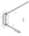
- Fig. 2 illustrates a side view of the watch strap with mounted on this clock.
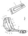
- Fig. 3 explains the disassembly or assembly of a watch strap according to the invention.
- Fig. 4 is a partially cut oblique view of one of the two band parts.
- the watch band shown in the figures has a central part 1 which extends from horns 2 on one side of a watch case 3 to the horns 2 on the opposite side of the watch case 3.
- the central part 1 is fastened with its ends 4 to the horns 2 of the watch case 3, preferably each by means of a conventional spring pin 5, the holes or holes 7 of the ends 4 passes through.
- the end portions 6 of the substantially parallel to the bottom of the watch case 3 extending central part 1 are bent toward the watch case 3, whereby a Distance 8 is formed between the top of the central part 1 and the underside of the watch case 3, so that the watch case 3 comes to rest practically above the arm of the wearer to form an air cushion 9.
- each band parts 10, 11 are detachably connected.
- the central part 1 has for this purpose in the longitudinal direction 14 of the central part 1 extending recesses 15 whose length is dimensioned so that the T-shaped end piece 13 of each band member 10, 11 can be threaded through the corresponding recesses 15.
- the T-shaped end pieces 13 are again parallel to the Ferderstatten 5 and at the end portions 6 of the central part, whereby a cohesion of the band parts 10, 11 and the central part 1 is secured.
- To remove a band part 10, 11 this in turn would have to be turned by 90 ° about its longitudinal axis, so that the T-shaped end piece 13 can slide out through the recess of the central part 1.
- the watchband is preferably made of vulcanized rubber, but it may also be formed of leather, metal or plastic. It is also possible to provide different materials for the central part 1 and the band parts.
- the T-shaped end pieces In order to achieve a sufficient strength of the Uhrarmbandes, in particular the T-shaped end pieces, even in an embodiment of the Uhrarmbandes from a less solid material, such as vulcanized rubber, these are appropriate, as in Fig. 4 illustrated reinforced with an insert 16, wherein this insert 16 extends from the T-shaped end piece 13 by means of an anchoring part 17 into the adjoining end portion of the band member 10 and 11, respectively.
- the reinforcement is preferably made of metal and completely incorporated into the material of the band portion 10 and 11, so that it is enveloped on all sides and thus remains invisible to the wearer.
- the invention is not limited to the embodiment shown in the drawing, but may be modified in various ways.
- the two band parts 10, 11 with other fastening means, such as snap connections be releasably secured to the central part 1.
- the embodiment shown in the figures with the T-shaped end pieces 13 of the band parts 10, 11 has proven particularly well because of the simplicity in terms of both production and handling.
Landscapes
- Physics & Mathematics (AREA)
- General Physics & Mathematics (AREA)
- Purses, Travelling Bags, Baskets, Or Suitcases (AREA)
- Orthopedics, Nursing, And Contraception (AREA)
Abstract
Description
- Die Erfindung betrifft ein Uhrarmband. Dieses soll einwandfrei am Uhrgehäuse befestigbar sein, ohne dass die Gefahr eines ungewollten Lösens besteht. Andererseits jedoch soll eine Anpassung des Uhrarmbands an die Wünsche des Trägers, beispielsweise hinsichtlich der Farbe, geometrischer Gestalt, etc. möglich sein. Hierbei ist es insbesondere von Bedeutung, dass ein solcher Wechsel eines Uhrarmbandes in besonders einfacher Weise vor sich gehen kann und zudem keinen komplizierten Mechanismus, der letztendlich störanfällig sein kann, erfordert. Der Wechsel soll vom Träger der Uhr selbst ohne Werkzeug und ohne eine Hilfestellung eines Uhrmachers durchgeführt werden können. Eine weitere Funktion, die das Uhrarmband erfüllen soll, ist ein Schutz der Uhr, insbesondere vor Stößen und vor dem Schweiß des Trägers. Üblicherweise werden Uhrarmbänder mittels Federstifte an den Hörnern des Uhrgehäuses befestigt.
- Zur Lösung dieser komplexen Aufgabe ist das erfindungsgemäße Uhrarmband durch die Kombination folgender Merkmale gekennzeichnet:
- einen von Hörnern an einer Seite eines Uhrgehäuses bis zu Hörnern an der gegenüberliegenden Seite des Uhrgehäuses reichenden und das Uhrgehäuse an dessen Unterseite klammerartig übergreifenden Zentralteil,
- der mit seinen Enden an den Hörnern des Uhrgehäuses befestigbar ist und
- an dessen beiden Endbereichen jeweils ein Bandteil des Uhrarmbandes lösbar angeschlossen ist.
- Durch die Verlagerung der Befestigung der Bandteile weg vom Uhrgehäuse, nämlich zu den Endbereichen des Zentralteiles, lassen sich einfache und auch für Nicht-Fachleute leicht zu bedienende und trotzdem sicher haltende Befestigungselemente zum Wechseln der Bandteile vorsehen.
- Durch den Zentralteil ist das Uhrgehäuse in einer Distanz vom Unterarm bzw. Handgelenk des Trägers gehalten, und es kann der Boden des Uhrgehäuses nicht mehr durch Schweiß des Trägers benetzt werden. Infolge des Materials des Zentralteils ergibt sich auch ein guter Schutz des Uhrgehäuses gegen Stöße.
- Eine bevorzugte Variante des Uhrarmbands ist dadurch gekennzeichnet, dass der Zentralteil mit eine Distanz zur Unterseite des Uhrgehäuses festlegenden und zum Uhrgehäuse aufragenden Endbereichen versehen ist, deren Enden an den Hörnern befestigbar sind.
- Das Vorsehen dieser Distanz zwischen dem Zentralteil und der Unterseite des Uhrgehäuses ermöglicht eine besonders gute Schockabsorption und damit einen guten Schutz des Uhrgehäuses gegen Stöße. Dies insbesondere dann, wenn der Zentralteil aus einem elastisch flexiblen bzw. federnden Material, wie Gummi, gebildet ist, was für Uhrarmbänder mehr oder weniger üblich ist. Auch könnte der Zentralteil aus Metall, wie Federstahl, gebildet sein.
- Ein besonders einfaches Austauschen der beiden Bandteile ist gegeben, wenn die Bandteile jeweils ein T-förmiges, sich in der Ebene der Bandteile erstreckendes Endstück aufweisen, das in sich in Längsrichtung des Zentralteiles erstreckende schlitzförmige Ausnehmungen einsetzbar ist.
- Damit das Uhrarmband auch größeren Belastungen standhalten kann, ist eine das T-förmige Endstück der Bandteile verstärkende Einlage vorzugsweise vom T-förmigen Endstück allseitig umschlossen, wobei zweckmäßig die Einlage im T-förmigen Endstück mit einem in den Endbereich des Bandteils ragenden Verankerungsteil versehen ist, der vorzugsweise vom Endbereich des Bandteils allseitig umschlossen ist.
- Zweckmäßig ist die Einlage aus Metall gebildet.
- Vorzugsweise ist der Zentralteil und/oder sind die Bandteile des Uhrarmbandes aus Leder, Kunststoff oder vulkanisiertem und thermoplastischem Gummi gebildet.
- Die Erfindung ist nachfolgend anhand eines in der Zeichnung schematisch dargestellten Ausführungsbeispiels näher erläutert, wobei
Fig. 1 eine Schrägrissdarstellung des Uhrarmbandes zeigt.Fig. 2 veranschaulicht eine Seitenansicht des Uhrarmbandes mit an diesem montierter Uhr.Fig. 3 erläutert das Zerlegen bzw. Zusammensetzen eines erfindungsgemäßen Uhrarmbandes.Fig. 4 ist eine teilweise geschnittene Schrägrissansicht eines der beiden Bandteile. - Das in den Figuren dargestellte Uhrarmband weist einen Zentralteil 1 auf, der sich von Hörnern 2 an einer Seite eines Uhrgehäuses 3 bis zu den Hörnern 2 an der gegenüberliegenden Seite des Uhrgehäuses 3 erstreckt. Der Zentralteil 1 ist mit seinen Enden 4 an den Hörnern 2 des Uhrgehäuses 3 befestigbar, und zwar vorzugsweise jeweils mittels eines herkömmlichen Federstiftes 5, der Bohrungen bzw. Löcher 7 der Enden 4 durchsetzt. Die Endbereiche 6 des sich im wesentlichen parallel zum Boden des Uhrgehäuses 3 erstreckenden Zentralteils 1 sind zum Uhrgehäuse 3 hin gebogen ausgebildet, wodurch eine Distanz 8 zwischen der Oberseite des Zentralteils 1 und der Unterseite des Uhrgehäuses 3 gebildet ist, sodass das Uhrgehäuse 3 praktisch oberhalb des Arms des Trägers unter Ausbildung eines Luftpolsters 9 zu liegen kommt.
- An den Endbereichen 6 des Zentralteils 1 sind jeweils Bandteile 10, 11 lösbar angeschlossen. Jeder Bandteil 10, 11, von denen einer die Schnalle trägt und ein anderer die dazu korrespondierenden Ösen 12 aufweist, weist ein T-förmig ausgebildetes Endstück 13 auf, wobei sich das T-förmige Endstück 13 in der Ebene der Bandteile 10, 11 erstreckt. Der Zentralteil 1 weist hierzu korrespondierend sich in Längsrichtung 14 des Zentralteils 1 erstreckende Ausnehmungen 15 auf, deren Länge so bemessen ist, dass das T-förmige Endstück 13 jedes Bandteils 10, 11 durch die entsprechenden Ausnehmungen 15 einfädelbar ist. Durch anschließendes Wenden des eingesetzten Bandteils 10 bzw. 11 um 90° liegen die T-förmigen Endstücke 13 wiederum parallel zu den Ferderstiften 5 sowie an den Endbereichen 6 des Zentralteils an, wodurch ein Zusammenhalt der Bandteile 10, 11 und des Zentralteils 1 gesichert ist. Zum Ausbau eines Bandteiles 10, 11 müsste dieser wiederum um 90° um seine Längsachse gewendet werden, sodass das T-förmige Endstück 13 durch die Ausnehmung des Zentralteiles 1 herausgleiten kann.
- Das Uhrarmband ist vorzugsweise aus vulkanisiertem Gummi hergestellt, es kann jedoch auch aus Leder, Metall oder Kunststoff gebildet sein. Es ist auch möglich, unterschiedliche Materialien für den Zentralteil 1 und die Bandteile vorzusehen.
- Um auch bei einer Ausbildung des Uhrarmbandes aus einem weniger festen Material, wie z.B. aus vulkanisiertem Gummi, eine hinreichende Festigkeit des Uhrarmbandes zu erzielen, insbesondere der T-förmigen Endstücke, sind diese zweckmäßig, wie in
Fig. 4 veranschaulicht, mit einer Einlage 16 verstärkt, wobei sich diese Einlage 16 vom T-förmigen Endstück 13 mittels eines Verankerungsteils 17 bis in den daran anschließenden Endbereich des Bandteils 10 bzw. 11 erstreckt. Die Verstärkung ist vorzugsweise aus Metall und komplett in das Material des Bandteils 10 bzw. 11 eingearbeitet, sodass es allseitig umhüllt ist und damit für den Träger unsichtbar bleibt. - Die Erfindung beschränkt sich nicht auf das in der Zeichnung dargestellte Ausführungsbeispiel, sondern kann in verschiedener Hinsicht modifiziert sein. Beispielsweise können die beiden Bandteile 10, 11 auch mit anderen Befestigungsmitteln, wie z.B. Schnappverbindungen, am Zentralteil 1 lösbar befestigt sein. Die in den Figuren dargestellte Ausführungsform mit den T-förmigen Endstücken 13 der Bandteile 10, 11 hat sich wegen der Einfachheit sowohl hinsichtlich Herstellung als auch Handhabung besonders gut bewährt.
Claims (6)
- Uhrarmband, gekennzeichnet durch die Kombination folgender Merkmale:- einen von Hörnern (2) an einer Seite eines Uhrgehäuses (3) bis zu Hörnern (2) an der gegenüberliegenden Seite des Uhrgehäuses (3) reichenden und das Uhrgehäuse (3) an dessen Unterseite klammerartig übergreifenden Zentralteil (1),- der mit seinen Enden (4) an Hörnern (2) des Uhrgehäuses (3) befestigbar ist,- der mit eine Distanz (8) zur Unterseite des Uhrgehäuses (3) festlegenden und zum Uhrgehäuse (3) aufragenden Endbereichen (6) versehen ist und- an den beiden Endbereichen (6) jeweils ein Bandteil (10, 11) des Uhrarmbandes lösbar angeschlossen ist.
- Uhrarmband nach Anspruch 1, dadurch gekennzeichnet, dass die Bandteile (10, 11) jeweils ein T-förmiges, sich in der Ebene der Bandteile (10, 11) erstreckendes Endstück (13) aufweisen, das in sich in Längsrichtung (14) des Zentralteiles (1) erstreckende schlitzförmige Ausnehmungen (15) einsetzbar ist.
- Uhrarmband nach Anspruch 2, gekennzeichnet durch eine das T-förmige Endstück (13) der Bandteile (10, 11) verstärkende Einlage, die vorzugsweise vom T-förmigen Endstück (13) allseitig umschlossen ist.
- Uhrarmband nach Anspruch 3, dadurch gekennzeichnet, dass die Einlage (16) im T-förmigen Endstück (13) mit einem in den Endbereich des Bandteils (10, 11) ragenden Verankerungsteil (17) versehen ist, der vorzugsweise vom Endbereich des Bandteils (10, 11) allseitig umschlossen ist.
- Uhrarmband nach Anspruch 3 oder 4, dadurch gekennzeichnet, dass die Einlage (16) aus Metall gebildet ist.
- Uhrarmband nach einem der Ansprüche 1 bis 5, dadurch gekennzeichnet, dass der Zentralteil (1) und/oder die Bandteile (10, 11) des Uhrarmbandes aus Leder, Kunststoff oder vulkanisiertem und thermoplastischem Gummi gebildet sind.
Applications Claiming Priority (1)
| Application Number | Priority Date | Filing Date | Title |
|---|---|---|---|
| AT0014708U AT10469U1 (de) | 2008-03-07 | 2008-03-07 | Uhrarmband |
Publications (1)
| Publication Number | Publication Date |
|---|---|
| EP2098131A2 true EP2098131A2 (de) | 2009-09-09 |
Family
ID=40373476
Family Applications (1)
| Application Number | Title | Priority Date | Filing Date |
|---|---|---|---|
| EP09450047A Withdrawn EP2098131A2 (de) | 2008-03-07 | 2009-03-03 | Uhrarmband |
Country Status (2)
| Country | Link |
|---|---|
| EP (1) | EP2098131A2 (de) |
| AT (1) | AT10469U1 (de) |
Cited By (18)
| Publication number | Priority date | Publication date | Assignee | Title |
|---|---|---|---|---|
| EP2505095A1 (de) * | 2011-04-01 | 2012-10-03 | Rolex Sa | Armband mit Komfortkissen |
| WO2016025279A3 (en) * | 2014-08-09 | 2016-04-14 | Apple Inc. | Attachment systems for electronic devices |
| US9877549B2 (en) | 2014-08-11 | 2018-01-30 | Apple Inc. | Attachment system for an electronic device |
| US9894964B2 (en) | 2014-08-11 | 2018-02-20 | Apple Inc. | Consumer product attachment systems having a locking assembly |
| US9926953B2 (en) | 2013-03-15 | 2018-03-27 | Apple Inc. | Attachment apparatuses and associated methods of use and manufacture |
| US9949537B2 (en) | 2015-03-06 | 2018-04-24 | Apple Inc. | Clasp mechanism for wrist-worn devices |
| US10064460B2 (en) | 2015-09-30 | 2018-09-04 | Apple Inc. | Frictional stabilization of band and securement mechanism |
| US10149518B1 (en) | 2016-08-08 | 2018-12-11 | Apple Inc. | Clasp assembly for a wearable device |
| US10184506B2 (en) | 2014-08-11 | 2019-01-22 | Apple Inc. | Captive elements of an attachment system |
| US10219591B2 (en) | 2016-03-21 | 2019-03-05 | Apple Inc. | Attachment system for an electronic device |
| CN111887550A (zh) * | 2020-07-30 | 2020-11-06 | 维沃移动通信有限公司 | 穿戴设备 |
| WO2022244964A1 (ko) * | 2021-05-18 | 2022-11-24 | 삼성전자 주식회사 | 결착 부재를 포함하는 전자 장치 |
| DE102022001279B3 (de) | 2022-04-08 | 2023-03-30 | Anatoli Pfeifer | Uhr und Verfahren zur Montage einer Uhr |
| US11986067B2 (en) | 2020-08-19 | 2024-05-21 | Masimo Corporation | Strap for a wearable device |
| USD1036293S1 (en) | 2021-08-17 | 2024-07-23 | Masimo Corporation | Straps for a wearable device |
| USD1092244S1 (en) | 2023-07-03 | 2025-09-09 | Masimo Corporation | Band for an electronic device |
| USD1095288S1 (en) | 2022-07-20 | 2025-09-30 | Masimo Corporation | Set of straps for a wearable device |
| US12495999B2 (en) | 2021-07-21 | 2025-12-16 | Masimo Corporation | Wearable band for health monitoring device |
Families Citing this family (1)
| Publication number | Priority date | Publication date | Assignee | Title |
|---|---|---|---|---|
| CN211154104U (zh) * | 2019-06-25 | 2020-08-04 | Oppo广东移动通信有限公司 | 可穿戴设备和表带 |
-
2008
- 2008-03-07 AT AT0014708U patent/AT10469U1/de not_active IP Right Cessation
-
2009
- 2009-03-03 EP EP09450047A patent/EP2098131A2/de not_active Withdrawn
Cited By (36)
| Publication number | Priority date | Publication date | Assignee | Title |
|---|---|---|---|---|
| US8870448B2 (en) | 2011-04-01 | 2014-10-28 | Rolex S.A. | Bracelet with comfort pad |
| EP2505095A1 (de) * | 2011-04-01 | 2012-10-03 | Rolex Sa | Armband mit Komfortkissen |
| US10132340B2 (en) | 2013-03-15 | 2018-11-20 | Apple Inc. | Attachment apparatuses and associated methods of use and manufacture |
| US11614108B2 (en) | 2013-03-15 | 2023-03-28 | Apple Inc. | Attachment apparatuses and associated methods of use and manufacture |
| US11480202B2 (en) | 2013-03-15 | 2022-10-25 | Apple Inc. | Attachment apparatuses and associated methods of use and manufacture |
| US9926953B2 (en) | 2013-03-15 | 2018-03-27 | Apple Inc. | Attachment apparatuses and associated methods of use and manufacture |
| US10914329B2 (en) | 2013-03-15 | 2021-02-09 | Apple Inc. | Attachment apparatuses and associated methods of use and manufacture |
| WO2016025279A3 (en) * | 2014-08-09 | 2016-04-14 | Apple Inc. | Attachment systems for electronic devices |
| US10016029B2 (en) | 2014-08-09 | 2018-07-10 | Apple Inc. | Attachment systems for electronic devices |
| US10893726B2 (en) | 2014-08-09 | 2021-01-19 | Apple Inc. | Attachment systems for electronic devices |
| US10085523B2 (en) | 2014-08-11 | 2018-10-02 | Apple Inc. | Attachment system for an electronic device |
| US9894964B2 (en) | 2014-08-11 | 2018-02-20 | Apple Inc. | Consumer product attachment systems having a locking assembly |
| US10182623B2 (en) | 2014-08-11 | 2019-01-22 | Apple Inc. | Consumer product attachment systems having locking or expansion characteristics |
| US10184506B2 (en) | 2014-08-11 | 2019-01-22 | Apple Inc. | Captive elements of an attachment system |
| US11723443B2 (en) | 2014-08-11 | 2023-08-15 | Apple Inc. | Consumer product attachment systems having locking or expansion characteristics |
| US10264857B2 (en) | 2014-08-11 | 2019-04-23 | Apple Inc. | Attachment system for an electronic device |
| US10575602B2 (en) | 2014-08-11 | 2020-03-03 | Apple Inc. | Consumer product attachment systems having a locking assembly |
| US9877549B2 (en) | 2014-08-11 | 2018-01-30 | Apple Inc. | Attachment system for an electronic device |
| US12127636B2 (en) | 2014-08-11 | 2024-10-29 | Apple Inc. | Attachment system for an electronic device |
| US11717060B2 (en) | 2014-08-11 | 2023-08-08 | Apple Inc. | Attachment system for an electronic device |
| US10945496B2 (en) | 2014-08-11 | 2021-03-16 | Apple Inc. | Consumer product attachment systems having locking or expansion characteristics |
| US11026484B2 (en) | 2014-08-11 | 2021-06-08 | Apple Inc. | Attachment system for an electronic device |
| US11006705B2 (en) | 2015-03-06 | 2021-05-18 | Apple Inc. | Clasp mechanism for wrist-worn devices |
| US9949537B2 (en) | 2015-03-06 | 2018-04-24 | Apple Inc. | Clasp mechanism for wrist-worn devices |
| US10064460B2 (en) | 2015-09-30 | 2018-09-04 | Apple Inc. | Frictional stabilization of band and securement mechanism |
| US10219591B2 (en) | 2016-03-21 | 2019-03-05 | Apple Inc. | Attachment system for an electronic device |
| US10149518B1 (en) | 2016-08-08 | 2018-12-11 | Apple Inc. | Clasp assembly for a wearable device |
| CN111887550A (zh) * | 2020-07-30 | 2020-11-06 | 维沃移动通信有限公司 | 穿戴设备 |
| CN111887550B (zh) * | 2020-07-30 | 2024-05-07 | 维沃移动通信有限公司 | 穿戴设备 |
| US11986067B2 (en) | 2020-08-19 | 2024-05-21 | Masimo Corporation | Strap for a wearable device |
| WO2022244964A1 (ko) * | 2021-05-18 | 2022-11-24 | 삼성전자 주식회사 | 결착 부재를 포함하는 전자 장치 |
| US12495999B2 (en) | 2021-07-21 | 2025-12-16 | Masimo Corporation | Wearable band for health monitoring device |
| USD1036293S1 (en) | 2021-08-17 | 2024-07-23 | Masimo Corporation | Straps for a wearable device |
| DE102022001279B3 (de) | 2022-04-08 | 2023-03-30 | Anatoli Pfeifer | Uhr und Verfahren zur Montage einer Uhr |
| USD1095288S1 (en) | 2022-07-20 | 2025-09-30 | Masimo Corporation | Set of straps for a wearable device |
| USD1092244S1 (en) | 2023-07-03 | 2025-09-09 | Masimo Corporation | Band for an electronic device |
Also Published As
| Publication number | Publication date |
|---|---|
| AT10469U1 (de) | 2009-04-15 |
Similar Documents
| Publication | Publication Date | Title |
|---|---|---|
| EP2098131A2 (de) | Uhrarmband | |
| EP2229836B1 (de) | Befestigungsvorrichtung für Armbänder | |
| CH698584B1 (de) | Armband für Zeitmesser sowie Armbanduhr. | |
| EP2540188A1 (de) | Befestigungsvorrichtung für Armbänder | |
| DE3104754A1 (de) | "skischuh" | |
| DE102010032855A1 (de) | Haftverschlussteil | |
| DE2738043C2 (de) | Sicherheits-Gesichtsschild gegen spritzendes Material | |
| EP0723750B1 (de) | Uhren-Armband und Verfahren zu dessen Herstellung | |
| EP2410887B1 (de) | Band, insbesondere uhrarmband, mit beweglicher schliesse | |
| WO2010057940A1 (de) | Armbanduhr | |
| DE102005026836A1 (de) | Handgriff für ein Kraftfahrzeug | |
| DE3627942A1 (de) | Uhr, insbesondere schmuckuhr, mit halterung | |
| EP1949811B1 (de) | Band, insbesondere zur Verwendung als Schmuck-oder Uhrarmband | |
| DE202006012832U1 (de) | Armband für eine Armbanduhr | |
| DE7814256U1 (de) | Tragvorrichtung fuer eine handharmonika | |
| AT12503U1 (de) | Integriertes armband | |
| DE29506686U1 (de) | Armbanduhr | |
| AT381846B (de) | Schubschlaufe | |
| DE1701641U (de) | Loesbare befestigung von haltebaendern, vorzugsweise von ledernen flachen haltebaendern an metalloesen oder metallschlaufen, z. b. von armbanduhren. | |
| EP0627208B1 (de) | Epicondylitis-Bandage | |
| AT13148U1 (de) | Armband | |
| EP3231313A1 (de) | Gehäuse für armbanduhren | |
| DE1251176B (de) | ||
| DE102020129778A1 (de) | Der pferdefreundliche Reitsporen | |
| DE2125332A1 (de) | Steigbügel |
Legal Events
| Date | Code | Title | Description |
|---|---|---|---|
| PUAI | Public reference made under article 153(3) epc to a published international application that has entered the european phase |
Free format text: ORIGINAL CODE: 0009012 |
|
| AK | Designated contracting states |
Kind code of ref document: A2 Designated state(s): AT BE BG CH CY CZ DE DK EE ES FI FR GB GR HR HU IE IS IT LI LT LU LV MC MK MT NL NO PL PT RO SE SI SK TR |
|
| AX | Request for extension of the european patent |
Extension state: AL BA RS |
|
| REG | Reference to a national code |
Ref country code: HK Ref legal event code: DE Ref document number: 1135291 Country of ref document: HK |
|
| STAA | Information on the status of an ep patent application or granted ep patent |
Free format text: STATUS: THE APPLICATION IS DEEMED TO BE WITHDRAWN |
|
| 18D | Application deemed to be withdrawn |
Effective date: 20141001 |
|
| REG | Reference to a national code |
Ref country code: HK Ref legal event code: WD Ref document number: 1135291 Country of ref document: HK |