EP2098321A2 - Unterer Sägeblattschutz - Google Patents
Unterer Sägeblattschutz Download PDFInfo
- Publication number
- EP2098321A2 EP2098321A2 EP09154265A EP09154265A EP2098321A2 EP 2098321 A2 EP2098321 A2 EP 2098321A2 EP 09154265 A EP09154265 A EP 09154265A EP 09154265 A EP09154265 A EP 09154265A EP 2098321 A2 EP2098321 A2 EP 2098321A2
- Authority
- EP
- European Patent Office
- Prior art keywords
- casing
- camming
- motor
- blade guard
- axis
- Prior art date
- Legal status (The legal status is an assumption and is not a legal conclusion. Google has not performed a legal analysis and makes no representation as to the accuracy of the status listed.)
- Withdrawn
Links
- 238000005520 cutting process Methods 0.000 claims abstract description 36
- 230000005540 biological transmission Effects 0.000 claims abstract description 27
- 210000003813 thumb Anatomy 0.000 description 12
- 230000008878 coupling Effects 0.000 description 2
- 238000010168 coupling process Methods 0.000 description 2
- 238000005859 coupling reaction Methods 0.000 description 2
- 230000000694 effects Effects 0.000 description 2
- 238000005461 lubrication Methods 0.000 description 2
- 238000004804 winding Methods 0.000 description 2
- 241001272720 Medialuna californiensis Species 0.000 description 1
- 239000002826 coolant Substances 0.000 description 1
- 230000003247 decreasing effect Effects 0.000 description 1
- 238000009826 distribution Methods 0.000 description 1
- 230000002349 favourable effect Effects 0.000 description 1
- 238000003780 insertion Methods 0.000 description 1
- 230000037431 insertion Effects 0.000 description 1
- 238000003754 machining Methods 0.000 description 1
- 238000004519 manufacturing process Methods 0.000 description 1
- 239000000463 material Substances 0.000 description 1
- 230000035515 penetration Effects 0.000 description 1
- 230000001737 promoting effect Effects 0.000 description 1
- 238000000926 separation method Methods 0.000 description 1
Images






Classifications
-
- B—PERFORMING OPERATIONS; TRANSPORTING
- B27—WORKING OR PRESERVING WOOD OR SIMILAR MATERIAL; NAILING OR STAPLING MACHINES IN GENERAL
- B27B—SAWS FOR WOOD OR SIMILAR MATERIAL; COMPONENTS OR ACCESSORIES THEREFOR
- B27B9/00—Portable power-driven circular saws for manual operation
-
- B—PERFORMING OPERATIONS; TRANSPORTING
- B27—WORKING OR PRESERVING WOOD OR SIMILAR MATERIAL; NAILING OR STAPLING MACHINES IN GENERAL
- B27G—ACCESSORY MACHINES OR APPARATUS FOR WORKING WOOD OR SIMILAR MATERIALS; TOOLS FOR WORKING WOOD OR SIMILAR MATERIALS; SAFETY DEVICES FOR WOOD WORKING MACHINES OR TOOLS
- B27G19/00—Safety guards or devices specially adapted for wood saws; Auxiliary devices facilitating proper operation of wood saws
- B27G19/02—Safety guards or devices specially adapted for wood saws; Auxiliary devices facilitating proper operation of wood saws for circular saws
- B27G19/04—Safety guards or devices specially adapted for wood saws; Auxiliary devices facilitating proper operation of wood saws for circular saws for manually-operated power-driven circular saws
Definitions
- the present invention relates to a power tool and in particular a Circular cutting saw as set out in appended claims 1 and 2 below.
- Circular cutting saws are commonly used in both residential and commercial applications. These circular saws typically include a motor casing surrounding a motor drive system. The circular saw may also include one or more handles for manipulating the saw prior to, during, and after operation.
- Conventional motor drive systems can include a motor operably driving a transmission coupled to a circular cutting blade or other implement.
- transmissions vary widely in the art, some include a worm drive system, which is often characterized by the use of a worm and wheel gearing system, oil bath coolant and lubrication, and an overall long, narrow aspect ratio of the motor casing in comparison to other circular saw designs.
- Such a problem may often manifest itself when cutting small slivers of the workpiece, or when attempting to cut out large (i.e. >45°) bevel angles. This is because the shape and /or geometry of those parts of these known blade guards which must contact the workpiece as the saw is moved into engagement with the workpiece mean they are often unable to make the necessary contact. This results in lack of movement of the blade guard thus failing to expose the blade.
- the shape and / or geometry of known blade guards can result in binding engagement with the workpiece. This snagging of the guard makes movement of the saw impossible.
- a power tool for cutting a workpiece having a number of advantageous features over conventional power tool designs.
- the power tool is provided for cutting a workpiece.
- the power tool can include a casing, an auxiliary handle assembly extending from the casing, a motor disposed at least partially in the casing, and a drive transmission operably coupled to the motor.
- the drive transmission outputs a driving force to a circular cutting blade in response to an input from the motor.
- the power tool further includes a movable blade guard pivotally coupled about an axis relative to the casing.
- the movable blade guard includes an inboard surface, an outboard surface, and an edge surface defining a cavity for receiving and, at least, partially concealing the circular cutting blade.
- the outboard surface of the movable blade guard defines a cam having a camming tip and a camming portion. The camming portion extends substantially along a radial line from the axis.
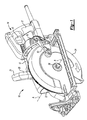
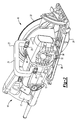
- Worm drive saw 10 comprises a motor and transmission casing 12 having a main handle assembly 14.
- Main handle assembly 14 can comprise an actuation trigger 15 for controlling a motor 16 and a gripping portion 17.
- Casing 12 is shaped to house motor 16 and a drive transmission 18 operably coupled to motor 16 for transmitting a power drive force from motor 16 to a circular cutting blade 19 ( FIG. 13 ).
- drive transmission 18 can be a worm drive transmission, which will be discussed in greater detail herein.
- alternative drive transmissions can be used in connection with the specific teachings of the present disclosure where appropriate. For example, direct gear drives or belt drives are possible.
- worm drive saw 10 further comprises an auxiliary handle assembly 20 fixedly coupled to a top portion of casing 12.
- auxiliary handle assembly 20 comprises a generally C-shaped member having a gripping portion 21 and fastening ends 23, which are sized and configured for mounting auxiliary handle assembly 20 to casing 12 via fasteners 25. This arrangement provides a secure and balanced position for carrying and/or tethering worm drive saw 10.
- Worm drive saw 10 includes an upper blade guard 22 coupled to or integrally formed with casing 12. Upper blade guard 22 remains in a fixed position relative to the circular cutting blade so as to protect an operator from debris and other material.
- a movable lower blade guard 24 is rotatably coupled to at least one of upper blade guard 22 or casing 12. More particularly, lower blade guard 24 includes a hub for rotatable coupling to an output drive shaft, which will be discussed in great detail herein.
- Lower blade guard 24 is configured such that it moves in a rotating direction about an axis A-A ( FIG. 1 ) of an output drive shaft when lower blade guard 24 abuts a workpiece to be cut 2000 ( FIG. 13 ).
- lower blade guard 24 is configured to provide an improved camming face relative to conventional lower blade guards along its outboard edge (see FIG. 9 ) so as to promote proper engagement with a workpiece during large bevel angle cuts and when cutting small portions of the workpiece.
- lower blade guard 24 comprises a generally half-moon shaped member concentric about a central hub 28 and a motor side surface 30 integrally formed with and radially extending from central hub 28.
- Central hub 28 as illustrated in FIG. 11 , can comprise a collar portion 32 having an internal diameter sized to cooperate with a bearing surface 34 ( FIG. 3 ) formed as part of at least one of casing 12, upper blade guard 22, or output drive shaft.
- This physical engagement of collar portion 32 of lower blade guard 24 and bearing surface 34 provides a smooth engagement for lower blade guard 24 to permit lower blade guard 24 to rotate out of position during operation in cooperation with a camming face, to be discussed.
- Lower blade guard 24 further comprises an outboard side surface 36 coupled to motor side surface 30 via an edge surface 38. Accordingly, motor side surface 30, outboard side surface 36, and edge surface 38 together defined an internal volume or cavity for receiving the circular cutting blade therein. As should be understood, lower blade guard 24 is biased from a retracted position, wherein the circular cutting blade is exposed, to a concealed position, wherein the circular cutting blade is covered and protected ( FIG. 3 ).
- outboard side surface 36 of lower blade guard 24 comprises various features which aid in the operation of worm drive saw 10.
- outboard side surface 36 comprises a cam 40 that is shaped and sized in accordance with the principles of the present teachings to provide improved workpiece engagement during large bevel angle cuts and/or small workpiece sliver cuts.
- Cam 40 comprises and extends from a camming tip 42 along a camming portion 44.
- Camming portion 44 generally extends from camming tip 42 to edge surface 38 of lower blade guard 24.
- camming portion 44 is shaped to include a slight arcuate curve that closely follows a radial line B-B extending from axis A-A.
- Camming portion 44 defines a tangent point or region C relative to radial line B-B. This tangent point or region C is disposed at a position about midpoint (i.e. about 50%) along the distance D, which extends from axis A-A to an internal surface of edge surface 38. This tangent point or region C can be disposed at a position about midpoint along cam 40.
- camming portion 44 namely its relation to radial line B-B, produces a driving moment promoting rotation of lower blade guard 24 about axis A-A to improve operation of worm drive saw 10 during large bevel angle cuts and/or a narrow sliver cuts. It should be appreciated that camming portion 44 defines a curvature and inclination that is reduced relative to conventional lower blade guards, such as illustrated in FIG. 9 .
- camming tip 42 of cam 40 extends to a position substantially adjacent the central axis of central hub 28. More particularly, as illustrated in FIG. 12 , camming tip 42 is positioned at an offset distance E that is less than 50% of distance D. Offset distance E of camming tip 42 can be less than 35% of distance D or even less than 25% of distance D (as shown in FIG. 12 ). According to this configuration, camming tip 42 can more quickly contact the workpiece during a cutting operation and, thus, begin rotation of lower blade guard 24 from its concealed position ( FIG. 1 ) to its retracted position.
- camming tip 42 defines a more elongated shape relative to conventional lower blade guards-that is, camming tip 42 extends closer to axis A-A (see FIG. 9 )-and permits quicker engagement of lower blade guard 24 against a workpiece during a cutting operation.
- lower blade guard 24 can further comprise a first connecting feature 48 for coupling a thumb lever 50 thereto ( FIGS. 1 and 3 ).
- Thumb lever 50 can be used by an operator to manually rotate lower blade guard 24 from the concealed position to the retracted position without the need for workpiece abutment.
- Lower blade guard 24 can further comprise a thumb gripping portion 52 for use during circular cutting blade replacement to conveniently hold lower blade guard 24 in the retracted position or intermediate position for simplified access to the circular cutting blade, which will be discussed in greater detail herein.
- Thumb gripping portion 52 can be formed as an extension from outboard side surface 36.
- thumb gripping portion 52 can be formed along a mid-section edge of outboard side surface 36 and can, in some embodiment, remain as a flat feature co-planar with outboard side surface 36. This can prevent inadvertent gripping and/or snagging of thumb gripping portion 52. Thumb gripping portion 52 can be positioned such that during a blade replacement operation, an operator can hold worm drive saw 10, at auxiliary handle assembly 20, and simultaneously hold lower blade guard 24 in a retracted position with a single hand.
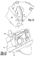
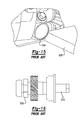
- conventional worm drive circular saw 1000 is illustrated having many of the disadvantages representative of the prior art.
- the illustrated conventional worm drive saw suffers from the inability to provide adequate clearance between its motor casing 1001 and its corresponding rip guide 1002 (also known as rip guide clearance).
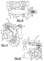
- conventional worm drive circular saw 1000 has a protrusion 1004 resulting from the placement of internal transmission drive components ( FIG. 16 ). That is, as illustrated in FIG. 16 , conventional worm drive circular saw 1000 employs a spindle lock 1008 disposed on an output drive shaft 1010 thereby increasing the overall length of output drive shaft 1010 and causing protrusion 1004 to extend outboard from motor casing 1001.
- this limits the thickness of a rip guide member 1006 ( FIG. 15 ), such as a worksite wooden member, that can be used.
- a rip guide member 1006 such as a worksite wooden member
- operators typically prefer to use any available elongated member present (i.e. rip guide member 1006) at a worksite to serve as a guide for defining a straight and even cut.
- This rip guide member 1006 can include any available straight cut lumber.
- the thickness of rip guide member 1006 is limited due to the interference caused between rip guide member 1006 and protrusion 1004 of conventional worm drive circular saw 1000.
- protrusion 1004 provides only a 1.13cm clearance between the bottom of rip guide 1002 and the lower edge of protrusion 1004. Consequently, this prevents an operator from using readily-available "1X" lumber (which has a thickness of about 1.69cm).
- drive transmission 18 of worm drive saw 10 is illustrated according to the principles of the present teachings.
- drive transmission 18 comprises an elongated armature drive shaft 54 having armature windings 56 ( FIG. 19 ) disposed about an end thereof.
- Armature shaft 54 is rotatably supported between an inner bearing 58, a fan end armature bearing 60, and an outer bearing 62.
- Armature shaft 54 is rotatable in response to electrical impulse passing through armature windings 56 in a conventional manner thereby producing a rotationally output driving force.
- Drive transmission 18 can comprise a spindle lock fan hub 64 positioned at an intermediate point on armature shaft 54.
- drive transmission 18 can further comprise a bearing retaining plate 72 having a recessed portion 73 formed therein sized to receive and retain fan end armature bearing 60.
- a worm gear 74 is fixedly coupled to armature shaft 54, such as through a key connection, for rotation therewith and in close relationship to fan end armature bearing 60.
- outer bearing 62 and a retaining nut 76 are positioned at an outer end 78 of armature shaft 54.
- each of the components disposed along armature shaft 54 can be progressively smaller in outer diameter than the adjacent component an armature shaft 54 to provide advantages in manufacturing and operation. That is, bearing retaining plate 72, fan end armature bearing 60, worm gear 74, outer bearing 62, and retaining nut 76 can each have an outer diameter smaller than the proceeding component, respectively.
- This progressively sized distribution of components and the use of bearing retaining plate 72 permits preassembly of armature shaft 54 with bearing retaining plate 72, fan end armature bearing 60, worm gear 74, outer bearing 62, and retaining nut 76 and further permits such pre-assembly to be easily installed and secured within casing 12.
- the pre-assembly is in effect a series of concentric cylinders or cones of successively decreasing diameter.
- This pre-assembly can be put together outside of casing 12, then installed in casing 12 through a single penetration in casing 12. Furthermore, this pre-assembly inhibits separation of such components due to gear drive forces. Still further, this pre-assembly reduces the amount of machining necessary on casing 12 and, thus, minimizes the number of holes that must be created in casing 12. This in turn reduces the opportunities for lubrication leakage.
- drive transmission 18 further comprises output drive shaft 26 having a corresponding worm gear 91 fixedly coupled thereto for rotation therewith and sized to enmeshingly engage worm gear 74 of armature shaft 54.
- Output drive shaft 26 can be supported for rotation by a first output drive shaft bearing 92 and a second output drive shaft bearing 94.
- first output drive shaft bearing 92 can be moved to the right in the figure ( FIG. 18 ). This movement of first output drive shaft bearing 92 to a more inboard location minimizes the protrusion effect (i.e.
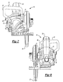
- worm drive saw 10 is able to achieve a greater distance between the lower portion of protrusion 96 and the lower edge of rip guide 98 (see FIGS. 4 and 22 ). Therefore, an operator can now use a standard (1X) wooden rip guide member having a thickness of about 1.69cm at a maximum depth cut setting. It should be appreciated that this is achieved due to the novel configuration of spindle lock mechanism 80 and the inboard relocation of first output drive shaft bearing 92 relative to conventional worm drive circular saw 1000. These advantages are also resultant from the novel configuration of a spindle lock mechanism.
- spindle lock mechanism 80 comprises spindle lock member 70 engagable with hub portion 66 of spindle lock fan hub 64.
- spindle lock member 70 can comprise a generally T-shaped member pivotally coupled to casing 12 or an intermediate surface at a pivot 82.
- Spindle lock member 70 further comprises a thumb pad 84 and a locking tab 86 opposite thereof.
- spindle lock fan hub 64 can comprise a hub portion 66 having a plurality of cavity locks 68 radially formed therein.
- Each cavity lock 68 includes a generally U-shaped depression accessible and engagable locking tab 86 of spindle lock member 70. It should be appreciated that variations exist as to the exact size, shape, and relative movement of spindle lock member 70 and spindle lock fan hub 64.
- Spindle lock mechanism 80 can further comprise a biasing spring 88 sufficiently sized to urge spindle lock member 70 into a disengaged position relative to spindle lock fan hub 64.
- spindle lock member 70 engages spindle lock fan hub 64 on armature shaft 54, a small turn of the circular cutting blade will cause many turns of armature shaft 54 and thus give many opportunities for engagement of locking tab 86 in one of the plurality of cavity locks 68, unlike conventional systems that use a spindle lock in connection with the output drive shaft..
- thumb pad 84 is positioned adjacent to auxiliary handle assembly 20 and in sufficiently close proximity such that an operator can hold worm drive saw 10 in one hand while simultaneously actuating thumb pad 84 with the same hand.
- This arrangement thus enables the operator to hold the power tool, prevent rotation of the circular cutting blade, and replace the circular cutting blade, without the need to place worm drive saw 10 on the ground or other supporting structure and in a favorable position.
- an operator can further retract lower blade guard 24 using thumb gripping portion 52 during the above replacement operation.
- spindle lock mechanism and/or transmission drive system can be adapted for use in other power tools.
Landscapes
- Life Sciences & Earth Sciences (AREA)
- Engineering & Computer Science (AREA)
- Mechanical Engineering (AREA)
- Wood Science & Technology (AREA)
- Forests & Forestry (AREA)
- Sawing (AREA)
- Grinding-Machine Dressing And Accessory Apparatuses (AREA)
Applications Claiming Priority (1)
| Application Number | Priority Date | Filing Date | Title |
|---|---|---|---|
| US12/042,401 US20090223069A1 (en) | 2008-03-05 | 2008-03-05 | Lower blade guard |
Publications (2)
| Publication Number | Publication Date |
|---|---|
| EP2098321A2 true EP2098321A2 (de) | 2009-09-09 |
| EP2098321A3 EP2098321A3 (de) | 2014-01-01 |
Family
ID=40810320
Family Applications (1)
| Application Number | Title | Priority Date | Filing Date |
|---|---|---|---|
| EP09154265.4A Withdrawn EP2098321A3 (de) | 2008-03-05 | 2009-03-04 | Unterer Sägeblattschutz |
Country Status (2)
| Country | Link |
|---|---|
| US (2) | US20090223069A1 (de) |
| EP (1) | EP2098321A3 (de) |
Cited By (2)
| Publication number | Priority date | Publication date | Assignee | Title |
|---|---|---|---|---|
| EP2409820A1 (de) * | 2010-07-22 | 2012-01-25 | Makita Corporation | Schneidewerkzeuge mit beweglichen Abdeckungsmontagestrukturen |
| CN107206615A (zh) * | 2014-10-30 | 2017-09-26 | 罗伯特·博世有限公司 | 用于圆锯的下锯片护罩 |
Families Citing this family (14)
| Publication number | Priority date | Publication date | Assignee | Title |
|---|---|---|---|---|
| US8695224B2 (en) * | 2007-09-13 | 2014-04-15 | Black & Decker Inc. | Saw with increased depth of cut |
| US20100236370A1 (en) * | 2009-03-20 | 2010-09-23 | Hassenboehler Jr Charles B | Cutting aid for a motorized saw |
| CN201483079U (zh) * | 2009-06-01 | 2010-05-26 | 南京德朔实业有限公司 | 直流电圆锯 |
| JP5507983B2 (ja) * | 2009-12-08 | 2014-05-28 | 株式会社マキタ | 丸鋸 |
| CA2845717C (en) * | 2010-08-18 | 2018-09-11 | Jacob Cuzdey | Convertible zero-clearance circular saw |
| USD802392S1 (en) | 2016-05-23 | 2017-11-14 | Cuz-D Manufacturing, Inc. | Circular saw blade |
| USD802393S1 (en) | 2016-05-23 | 2017-11-14 | Cuz-D Manufacturing, Inc. | Circular saw blade |
| USD819419S1 (en) | 2016-05-23 | 2018-06-05 | Cuz-D Manufacturing, Inc. | Circular saw blade |
| USD802391S1 (en) | 2016-05-23 | 2017-11-14 | Cuz-D Manufacturing, Inc. | Arbor for a circular saw |
| JP7049145B6 (ja) * | 2018-03-16 | 2022-04-19 | 株式会社マキタ | 電動工具 |
| US10875109B1 (en) | 2018-04-30 | 2020-12-29 | Kreg Enterprises, Inc. | Adaptive cutting system |
| CN111774654A (zh) * | 2019-04-04 | 2020-10-16 | 喜利得股份公司 | 圆锯 |
| CN113560664A (zh) * | 2020-04-28 | 2021-10-29 | 南京德朔实业有限公司 | 电圆锯 |
| CN113649641B (zh) * | 2020-05-12 | 2024-03-15 | 南京泉峰科技有限公司 | 电圆锯 |
Family Cites Families (38)
| Publication number | Priority date | Publication date | Assignee | Title |
|---|---|---|---|---|
| US3123109A (en) * | 1964-03-03 | Means for preventing loss of lubricant in gear chambers | ||
| US1672238A (en) * | 1926-08-13 | 1928-06-05 | J D Wallace & Company | Electric handsaw |
| US1932511A (en) * | 1926-10-04 | 1933-10-31 | Thomas B Bennett | Motor driven hand tool |
| US1780174A (en) * | 1928-01-16 | 1930-11-04 | Stanley Works | Portable power saw |
| US2543486A (en) * | 1945-06-08 | 1951-02-27 | Excel Auto Radiator Company | Portable power saw |
| US2671476A (en) * | 1950-02-02 | 1954-03-09 | Syntron Co | Portable belt-driven power handsaw |
| US2765824A (en) * | 1952-04-10 | 1956-10-09 | Porter Cable Machine Co | Portable power operated saw |
| US2828784A (en) * | 1956-10-17 | 1958-04-01 | Stanley Works | Saw blade guard for power driven portable circular saw with tiltable table |
| US2993518A (en) * | 1958-03-31 | 1961-07-25 | Skil Corp | Portable power driven saw |
| US3447577A (en) * | 1966-06-13 | 1969-06-03 | Stanley Works | Circular trim saw |
| US3701369A (en) * | 1970-07-27 | 1972-10-31 | Skil Corp | Circular saw |
| US3733701A (en) * | 1972-01-26 | 1973-05-22 | Singer Co | Lower guard for circular saws |
| DK151397C (da) * | 1979-02-23 | 1988-08-01 | Radiometer As | Fremgangsmaade og praeparat til brug ved drift af instrumenter, der analyserer proteinholdige biologiske vaesker |
| US4434586A (en) * | 1980-12-03 | 1984-03-06 | Robert Bosch Gmbh | Machine tool, especially a hand-held power tool with a turnable clamping element for clamping a tool on the tool spindle |
| US4402241A (en) * | 1981-08-10 | 1983-09-06 | Black & Decker Inc. | Spindle locking means for power operated tool |
| DE3317904A1 (de) * | 1983-05-17 | 1984-11-22 | Licentia Patent-Verwaltungs-Gmbh, 6000 Frankfurt | Handkreissaege mit pendelschutzhaube |
| DE3505041A1 (de) * | 1985-02-14 | 1986-08-14 | Licentia Patent-Verwaltungs-Gmbh, 6000 Frankfurt | Handkreissaege oder dergleichen elektrowerkzeug mit einem zweischalig ausgebildeten motor- und getriebegehaeuse |
| DE4100412A1 (de) * | 1991-01-09 | 1992-07-16 | Bosch Gmbh Robert | Elektrische handdrehwerkzeugmaschine, insbesondere handkreissaege |
| GB9225441D0 (en) * | 1992-12-04 | 1993-01-27 | Black & Decker Inc | A saw |
| US5361501A (en) * | 1993-08-23 | 1994-11-08 | Aleksander Fajnsztajn | Improved guard for power circular saw |
| US5396706A (en) * | 1993-08-23 | 1995-03-14 | Fajnsztajn; Aleksander | Guard for portable circular saws |
| USD370162S (en) * | 1993-12-17 | 1996-05-28 | Ryobi Motor Products Corp. | Circular saw |
| US5481806A (en) * | 1994-06-27 | 1996-01-09 | Pratt; Edgar L. | Tongue attachment for circular saw |
| US5724875A (en) * | 1995-10-10 | 1998-03-10 | Black & Decker Inc. | Guard and control apparatuses for sliding compound miter saw |
| US6971297B1 (en) * | 1995-10-10 | 2005-12-06 | Black & Decker Inc. | Guard and control apparatuses for sliding compound miter saw |
| US5957021A (en) * | 1995-10-10 | 1999-09-28 | Black & Decker, Inc. | Guard and control apparatuses for sliding compound miter saw |
| US6182548B1 (en) * | 1995-10-10 | 2001-02-06 | Black & Decker Inc. | Guard and control apparatuses for sliding compound miter saw |
| US5996706A (en) * | 1996-05-22 | 1999-12-07 | Cbj. Plating And Machine Of Tennessee | Grader circle and beam assembly |
| SE507264C2 (sv) * | 1996-06-13 | 1998-05-04 | Atlas Copco Tools Ab | Handhållet motordrivet verktyg |
| AU7688498A (en) * | 1997-05-19 | 1998-12-11 | Stephen S. Daniell | Powered cutting saw system and method for joining materials |
| US6202311B1 (en) * | 1999-07-30 | 2001-03-20 | Black & Decker Inc. | Circular saw with bevel angle adjustment mechanism |
| US6955167B2 (en) * | 2002-03-18 | 2005-10-18 | Electrolux Professional Outdoor Products, Inc. | Pavement working apparatus and methods of making |
| US20060201492A1 (en) * | 2002-03-18 | 2006-09-14 | Anthony Baratta | Methods and apparatus for movable machining tools including for wall saws |
| US6892619B1 (en) * | 2003-12-04 | 2005-05-17 | Chin-Chin Chang | Circular saw |
| US7980325B2 (en) * | 2004-01-16 | 2011-07-19 | Credo Technology Corporation | Rotating shaft locking mechanism |
| EP1772221B1 (de) * | 2005-10-07 | 2009-01-14 | Black & Decker | Säge |
| EP1772239B1 (de) * | 2005-10-07 | 2013-10-09 | Black & Decker, Inc. | Säge |
| US20070163412A1 (en) * | 2006-01-15 | 2007-07-19 | Anthony Baratta | Methods and apparatus for movable machining tools, including for wall saws |
-
2008
- 2008-03-05 US US12/042,401 patent/US20090223069A1/en not_active Abandoned
-
2009
- 2009-03-04 EP EP09154265.4A patent/EP2098321A3/de not_active Withdrawn
-
2011
- 2011-06-02 US US13/151,796 patent/US20110239472A1/en not_active Abandoned
Cited By (2)
| Publication number | Priority date | Publication date | Assignee | Title |
|---|---|---|---|---|
| EP2409820A1 (de) * | 2010-07-22 | 2012-01-25 | Makita Corporation | Schneidewerkzeuge mit beweglichen Abdeckungsmontagestrukturen |
| CN107206615A (zh) * | 2014-10-30 | 2017-09-26 | 罗伯特·博世有限公司 | 用于圆锯的下锯片护罩 |
Also Published As
| Publication number | Publication date |
|---|---|
| EP2098321A3 (de) | 2014-01-01 |
| US20090223069A1 (en) | 2009-09-10 |
| US20110239472A1 (en) | 2011-10-06 |
Similar Documents
| Publication | Publication Date | Title |
|---|---|---|
| EP2098321A2 (de) | Unterer Sägeblattschutz | |
| US20110088267A1 (en) | Worm Drive Saw | |
| EP2368659B1 (de) | Schwenkklingenhaltevorrichtung | |
| CA2790967C (en) | Saw assembly with floating bearing for worm drive and motor shaft | |
| EP1704023B1 (de) | Drehwellenverriegelungsmechanismus | |
| US8621967B2 (en) | Rotating spindle for a reciprocating saw | |
| DE102012217532B4 (de) | Sägenanordnung | |
| US11925993B2 (en) | Accessories for oscillating power tools | |
| US9434015B2 (en) | Saw assembly with bevel gear drivetrain | |
| EP0213172B1 (de) | Zurückfederndes schutzblech für scheibenmesserwerkzeuge | |
| US9089941B2 (en) | Circular saw guard system | |
| US5140754A (en) | Power tool protective hood positioning system and method of manufacturing the same | |
| US20060096428A1 (en) | Riving knife assembly | |
| TW201436906A (zh) | 具有快速釋放反回踢裝置的動力設備 | |
| CA2790976C (en) | Lockout forward flip lever for power saw | |
| EP2929969B1 (de) | Sägevorrichtung mit kegelradgetriebeantriebsstrang | |
| CN1984556A (zh) | 用于树蓠切割机等的设备 | |
| CA2791316C (en) | Base with beveled lateral side surface | |
| CA2790965C (en) | Power saw miter cutting guide | |
| CA2790990C (en) | Power saw crown molding cutting guide | |
| EP2969434B1 (de) | Klingenschutz für eine motorsäge | |
| US20130081288A1 (en) | Pipe Deburring Accessory for Circular Saw |
Legal Events
| Date | Code | Title | Description |
|---|---|---|---|
| PUAI | Public reference made under article 153(3) epc to a published international application that has entered the european phase |
Free format text: ORIGINAL CODE: 0009012 |
|
| AK | Designated contracting states |
Kind code of ref document: A2 Designated state(s): AT BE BG CH CY CZ DE DK EE ES FI FR GB GR HR HU IE IS IT LI LT LU LV MC MK MT NL NO PL PT RO SE SI SK TR |
|
| AX | Request for extension of the european patent |
Extension state: AL BA RS |
|
| PUAL | Search report despatched |
Free format text: ORIGINAL CODE: 0009013 |
|
| AK | Designated contracting states |
Kind code of ref document: A3 Designated state(s): AT BE BG CH CY CZ DE DK EE ES FI FR GB GR HR HU IE IS IT LI LT LU LV MC MK MT NL NO PL PT RO SE SI SK TR |
|
| AX | Request for extension of the european patent |
Extension state: AL BA RS |
|
| RIC1 | Information provided on ipc code assigned before grant |
Ipc: B23D 45/16 20060101ALI20131128BHEP Ipc: B27B 9/00 20060101ALI20131128BHEP Ipc: B27G 19/04 20060101AFI20131128BHEP |
|
| AKY | No designation fees paid | ||
| REG | Reference to a national code |
Ref country code: DE Ref legal event code: R108 |
|
| REG | Reference to a national code |
Ref country code: DE Ref legal event code: R108 Effective date: 20140903 |
|
| STAA | Information on the status of an ep patent application or granted ep patent |
Free format text: STATUS: THE APPLICATION IS DEEMED TO BE WITHDRAWN |
|
| 18D | Application deemed to be withdrawn |
Effective date: 20140702 |