EP2098352A2 - Outil de moulage par injection - Google Patents
Outil de moulage par injection Download PDFInfo
- Publication number
- EP2098352A2 EP2098352A2 EP09003008A EP09003008A EP2098352A2 EP 2098352 A2 EP2098352 A2 EP 2098352A2 EP 09003008 A EP09003008 A EP 09003008A EP 09003008 A EP09003008 A EP 09003008A EP 2098352 A2 EP2098352 A2 EP 2098352A2
- Authority
- EP
- European Patent Office
- Prior art keywords
- mold
- injection mold
- molding
- injection
- wall
- Prior art date
- Legal status (The legal status is an assumption and is not a legal conclusion. Google has not performed a legal analysis and makes no representation as to the accuracy of the status listed.)
- Granted
Links
- 238000001746 injection moulding Methods 0.000 title claims abstract description 22
- 238000000465 moulding Methods 0.000 claims description 104
- 238000002347 injection Methods 0.000 claims description 53
- 239000007924 injection Substances 0.000 claims description 53
- 230000015572 biosynthetic process Effects 0.000 claims description 7
- 230000006835 compression Effects 0.000 claims 2
- 238000007906 compression Methods 0.000 claims 2
- 239000010410 layer Substances 0.000 description 8
- 239000000463 material Substances 0.000 description 6
- 238000005253 cladding Methods 0.000 description 5
- 238000005553 drilling Methods 0.000 description 4
- 238000000034 method Methods 0.000 description 4
- 230000008569 process Effects 0.000 description 4
- 239000000243 solution Substances 0.000 description 4
- 230000001360 synchronised effect Effects 0.000 description 3
- 230000009471 action Effects 0.000 description 2
- 239000011247 coating layer Substances 0.000 description 2
- 238000005507 spraying Methods 0.000 description 2
- 238000009825 accumulation Methods 0.000 description 1
- 238000004873 anchoring Methods 0.000 description 1
- 230000008901 benefit Effects 0.000 description 1
- 230000008859 change Effects 0.000 description 1
- 150000001875 compounds Chemical class 0.000 description 1
- 238000010276 construction Methods 0.000 description 1
- 230000008878 coupling Effects 0.000 description 1
- 238000010168 coupling process Methods 0.000 description 1
- 238000005859 coupling reaction Methods 0.000 description 1
- 230000004048 modification Effects 0.000 description 1
- 238000012986 modification Methods 0.000 description 1
Images


Classifications
-
- B—PERFORMING OPERATIONS; TRANSPORTING
- B29—WORKING OF PLASTICS; WORKING OF SUBSTANCES IN A PLASTIC STATE IN GENERAL
- B29C—SHAPING OR JOINING OF PLASTICS; SHAPING OF MATERIAL IN A PLASTIC STATE, NOT OTHERWISE PROVIDED FOR; AFTER-TREATMENT OF THE SHAPED PRODUCTS, e.g. REPAIRING
- B29C45/00—Injection moulding, i.e. forcing the required volume of moulding material through a nozzle into a closed mould; Apparatus therefor
- B29C45/17—Component parts, details or accessories; Auxiliary operations
- B29C45/26—Moulds
- B29C45/33—Moulds having transversely, e.g. radially, movable mould parts
- B29C45/332—Mountings or guides therefor; Drives therefor
-
- B—PERFORMING OPERATIONS; TRANSPORTING
- B29—WORKING OF PLASTICS; WORKING OF SUBSTANCES IN A PLASTIC STATE IN GENERAL
- B29C—SHAPING OR JOINING OF PLASTICS; SHAPING OF MATERIAL IN A PLASTIC STATE, NOT OTHERWISE PROVIDED FOR; AFTER-TREATMENT OF THE SHAPED PRODUCTS, e.g. REPAIRING
- B29C45/00—Injection moulding, i.e. forcing the required volume of moulding material through a nozzle into a closed mould; Apparatus therefor
- B29C45/16—Making multilayered or multicoloured articles
- B29C45/1635—Making multilayered or multicoloured articles using displaceable mould parts, e.g. retractable partition between adjacent mould cavities
Definitions
- the invention relates to an injection molding tool as described in the preamble of claim 1.
- EP 1 820 738 A1 is an injection mold for producing a transport box comprising at least two relatively adjustable mold elements known in a projecting position a mold cavity, for injection molding a, a bottom and side walls of the transport box forming base shell, limit and at least one mold element to provide an additional mold cavity for the Injection of an envelope layer connected to the base shell is adjustably mounted relative to the projection position.
- the object of the invention is to provide an injection mold with a core mold part having tool base and the core molding at least partially in a variable distance to form a variable cavity enclosing wall and Eckform turnover in which an adjustment of the mold parts for a region-wise modification of the cavity and a Opening the injection mold for removal of the molding is achieved with a small number of drive components.
- This object of the invention is achieved by the reproduced in the characterizing part of claim 1 features.
- the surprising advantage is that thereby a drive coupling achieved between the core mold part for an injection molding enclosing moldings which ensures a synchronous movement of the moldings in a position remote from the core mold part position and an additional relative adjustment of the corner moldings is achieved to the wall moldings.
- the advantageous embodiment as described in claim 9 ensures an exact guidance of the adjustment process along the inclined Verstellebenen for a distancing of the wall moldings from the core molding relative to each other moving wall moldings.
- embodiments according to claims 22 to 25 are advantageous, since thus the wedge is supported against the action of the force exerted by the pressure in the cavity during injection of the plastic mass on the Eckformteil force by the locked during the injection molding wall moldings and thus a force on the guide element whose attachment and the linear guide assembly is effectively avoided. This ensures small dimensions of the components in the corners and thus overall smaller and weight and cost-saving injection molds.
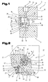
- FIG. 1 and 2 is a detail of an injection mold 1, consisting of a lower mold part 2 and a upper mold part 3, which are adjustable relative to each other, shown in the formation of a mold corner 4.
- the injection mold 1 is stretched with the lower mold part 2 and the upper mold part 3 in an injection molding machine, not shown, through which the relative adjustment for closing and opening of the injection mold 1 for an injection process and a removal operation of a molded part 5 takes place.
- the injection molding 5 is, for example, a transport box 6, in particular bottle crate 7, as described in detail below in a simplified representation of Fig. 3 can be seen.
- This consists of a box base 8 and four with the box bottom 8 an inner space 9 bounding side walls 10 and the interior 9 dividing réellegefache 11th
- the box bottom 8 forms with the side walls 10 and the réellegefache 11 a one-piece base shell which may also be double-walled by the formation of cavities, in particular to avoid accumulation of material.
- the figure shows a substantially rectangular box with box bottom 8 and four side walls 10, which are aligned at right angles to each other. Rectangular to the box bottom 8 extending box edges 13 are rounded and is applied in these areas on the base shell of a first plastic a to the box edge 13 and a portion of a side wall height 14 extending envelope layer 15 of a second plastic.
- the cladding layer 15 consists, for example, of the plastic material of the base shell 12 of different plastic material with different mechanical properties and / or a design element, e.g. differs in color from the material of the base shell 12.
- the injection mold 1 is in the Fig. 1 and 2 in the for injection molding of the base shell 12 closed position in which the upper mold part 3 and the lower mold part 2 are adjusted to each other and between a bottom mold part 16 and side wall parts 17 of the upper mold part 3 and a core mold part 18 of the mold part 2, a cavity 19 for injecting the plastic mass and thus to form the box bottom 8 with the Side walls 10 corresponding to an intended wall thickness or wall education exists.
- the mold corner 4 between the adjacent and an angle of 90 ° to each other enclosing wall moldings 12 is formed by a, arranged in a miter angle of 45 ° Eckformteil 20, with the core mold part 18 facing, formed by an internally rounded groove molding surface 21 on the core molding 18th , optionally over a height 22 of the Eckformteil 20, partially applied to the core molding 18.
- the corner molding 20 comprises with the profiled molding surface 21, the edge edge 13 corresponding to an intended dimension of the applied to the base shell 12 in the further injection molding coating layer 15th
- the corner molding 20 is fitted between opposite miter surfaces 23, 24 of the wall moldings 17, wherein the miter faces 23, 24 on side surfaces 25, 26 of the Eckformteils 20 in the closed state of the injection mold 1 tight fit.
- the corner molding 20 is adjustable between the miter surfaces 23, 24 of the wall moldings 17 in the plane of the 45 ° Miter angle in two positions.
- vertical actuator 30 is arranged in the upper mold part 3 a, acting on a, formed by a clamping surface 28 in the upper mold part 3 level 29 vertical actuator 30 is arranged.
- the actuator 30 for the Eckformteil 20 is generally formed by a arranged in a platen 32 of the upper mold part 3 adjusting means 33, eg hydraulic cylinder 34, with a perpendicular to the clamping surface 28 aligned piston rod 35 and an actuatable wedge 36.
- the adjusting wedge 36 has with respect to the linear guide assembly 37 in the direction of adjustment - according to double arrow 39 - inclined running guide assembly 40 with a T-groove guide 41, in which the Eckformteil 20 is guided with a counter-trained Systemssfortsatz on one of the mold surface 21 opposite back.
- a linear adjustment of the corner molding 20 in a direction parallel to the plane 29 - according to Doppepfeil 27 - causes.
- a driver element 42 for a positioning of the corner molding 20 with respect to the adjacent wall moldings 17, regardless of their variable position with respect to the clamping surface 28 of the platen 32, a driver element 42, in the illustrated embodiment, a cylindrical pin 43, the corner molding 20 in a slot 44 formed Guide means 45 crossing, provided.
- This is arranged in bores 46, 47 in the opposing miter surfaces 23, 24 of the wall moldings 17 and thus extends a longitudinal central axis 48 of the cylindrical pin 43 perpendicular to the adjustment direction - according to double arrow 27 - the corner molding 20th
- the cylindrical pin 43 is, for example, in one of the bores 46, 47 supported via a press fit and received in the further bore 46, 47 via a sliding seat.
- the slot 44 extends in the adjustment direction - according to double arrow 27 - of the corner molding 20, whereby its adjustment is ensured by means of the wedge 36 at the desired intervals of the molding surface 21 to the core molding 18.
- a total length 49 of the adjusting wedge 36 in the direction of its actuating direction - according to double arrow 39 - is smaller than an inner height 50 between the contact surface 48 in the lower mold part 2 and the clamping surface 28 of the upper mold part.
- the position of the corner molding 20 for molding the cladding layer 14 on the base shell 12 is shown.
- the adjusting wedge 36 is adjusted by means of the adjusting means 30 in an upper stop position in which this is adjusted against the clamping surface 28.
- the core mold member 20 is adjusted with its mold surface 21 to form a predetermined distance from the core mold part 18. In this position, the injection of the further plastic material into the released cavity takes place in the edge region of the transport box 6.
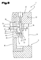
- the injection mold 1 is shown in a partially open position, wherein the removal movement of the injection molding is not yet completed, ie that for the removal of the molding a final distance 51 between the mold base 2 and the upper mold part 3 in the illustration shown is not yet reached.
- the side wall parts 17 are not shown further and known from the prior art actuators, e.g. Hydraulic cylinder, adjusted by the system at the clamping surface 28 of the clamping plate 32 by a distance 53. This adjustment takes place along inclined guide columns 54 which are arranged fixed in a bore 55 of the clamping plate 32. Bearing bushes 56 in holes 57 of the side wall parts 17 ensure precise guidance of the side wall parts 17 for an adjustment in inclined planes corresponding to an angle 58 of the inclined position of the guide columns 54 relative to the clamping surface 28.
- the angle 58 is preferably about 60 °.
- this cylindrical pin 43 in conjunction with the guide means 45 formed by the elongated hole 44 in the corner molding 20, by the relative movement relative to the wedge 36 which rests in its end position on contact with the clamping surface 28 and in conjunction with the inclined T. -Nut Adjust 41 between the wedge 36 and the Eckformteil 20 a further adjustment of the corner molding 20, according to - arrow 60 - for a further distancing of the molding surface 21 of the corner molding 20 from the core molding 18th
- the corner molding 20 has a T-shaped cross-section and is a thickness 61 in the region of the mold surface 21 is smaller than a thickness 62 in the region of the T-groove guide 41.
- a support assembly 63 for the wedge 36 with the adjustably guided on this Eckformteil 20 is achieved by the adjusting wedge 36 facing support surfaces 64, 65 on the wall moldings 17, the force acting on the Eckformteil 20 force - according to arrow 66 - when injecting the plastic material in the cavity 19, respectively gegen Eisen at an angle of 45 ° to the force direction of the force - are aligned according to arrow 66 - and thus parallel outer surfaces 67, 68 of the wall moldings 17 are aligned.
- the adjusting wedge 36 is adapted by an approximately hexagonal cross-sectional formation of the orientation of the support surfaces 64, 65 whereby cooperating with the support surfaces 64, 65 contact surfaces 69, 70 for power dissipation in the wall moldings 17 can be achieved.
- This support assembly 63 allows small dimensions of the adjusting wedge 36 and the columnar guide member 38 to which the adjusting wedge 36 in the linear guide assembly 37 is adjustably guided and which is fixed to the end face of the clamping plate 32 and protrudes freely in the direction of the lower mold part 2.
Landscapes
- Engineering & Computer Science (AREA)
- Manufacturing & Machinery (AREA)
- Mechanical Engineering (AREA)
- Moulds For Moulding Plastics Or The Like (AREA)
- Injection Moulding Of Plastics Or The Like (AREA)
- Diaphragms For Electromechanical Transducers (AREA)
- Pens And Brushes (AREA)
Applications Claiming Priority (1)
| Application Number | Priority Date | Filing Date | Title |
|---|---|---|---|
| AT0033908A AT506606B1 (de) | 2008-03-03 | 2008-03-03 | Spritzgiesswerkzeug |
Publications (3)
| Publication Number | Publication Date |
|---|---|
| EP2098352A2 true EP2098352A2 (fr) | 2009-09-09 |
| EP2098352A3 EP2098352A3 (fr) | 2009-09-23 |
| EP2098352B1 EP2098352B1 (fr) | 2011-01-26 |
Family
ID=40756732
Family Applications (1)
| Application Number | Title | Priority Date | Filing Date |
|---|---|---|---|
| EP09003008A Active EP2098352B1 (fr) | 2008-03-03 | 2009-03-03 | Outil de moulage par injection |
Country Status (3)
| Country | Link |
|---|---|
| EP (1) | EP2098352B1 (fr) |
| AT (2) | AT506606B1 (fr) |
| DE (1) | DE502009000335D1 (fr) |
Cited By (6)
| Publication number | Priority date | Publication date | Assignee | Title |
|---|---|---|---|---|
| EP2599608A1 (fr) * | 2011-12-02 | 2013-06-05 | Haidlmair Holding GmbH | Outil de moulage par injection, notamment un outil à mâchoires mobiles |
| EP2808151A1 (fr) * | 2013-05-27 | 2014-12-03 | Schoeller Allibert GmbH | Mécanisme de déformation d'un outil de moulage par injection |
| CN116766512A (zh) * | 2022-03-09 | 2023-09-19 | 台州美途模塑有限公司 | 左右c柱上装饰板注塑模具及其非对称式侧抽成型机构 |
| CN116901372A (zh) * | 2023-07-10 | 2023-10-20 | 上海维科精密模塑股份有限公司 | 注塑模具及其用于注塑模具的滑块构件 |
| US20250050550A1 (en) * | 2023-08-11 | 2025-02-13 | Jung Chi Chiang | Demolding method and mold structure for extrusion molding |
| CN121756526A (zh) * | 2026-03-03 | 2026-03-31 | 宁波佰利模塑有限公司 | 一种车用装饰条加工模具 |
Families Citing this family (2)
| Publication number | Priority date | Publication date | Assignee | Title |
|---|---|---|---|---|
| DE202009007083U1 (de) | 2009-05-16 | 2009-08-06 | Delbrouck Gmbh | Quaderförmiger Flaschenkasten |
| DE102018106891B4 (de) * | 2018-03-22 | 2020-06-18 | Meusburger GmbH & Co. KG | Schiebereinheit für Spritz- und Druckgussformen |
Citations (2)
| Publication number | Priority date | Publication date | Assignee | Title |
|---|---|---|---|---|
| DE102005059976A1 (de) | 2005-12-13 | 2007-06-14 | Linpac Materials Handling (Germany) Gmbh | Verfahren und Spritzgußform zur Herstellung eines Transportkastens aus Kunststoff |
| EP1820738A1 (fr) | 2006-02-20 | 2007-08-22 | Haidlmair GmbH | Caisse de transport, en particulier caisse à bouteilles |
Family Cites Families (2)
| Publication number | Priority date | Publication date | Assignee | Title |
|---|---|---|---|---|
| DE2849145C3 (de) * | 1978-11-13 | 1981-12-24 | Maschinenfabrik Köppern GmbH & Co KG, 4320 Hattingen | Spritzgießform für Transportkästen, bei der Formbachken auf schrägen Führrungssäulen verschiebbar sind |
| DE10353751A1 (de) * | 2003-11-17 | 2005-06-30 | Theysohn Formenbau Gmbh | Verfahren zum Ausbilden eines Behälterabschnittes |
-
2008
- 2008-03-03 AT AT0033908A patent/AT506606B1/de not_active IP Right Cessation
-
2009
- 2009-03-03 EP EP09003008A patent/EP2098352B1/fr active Active
- 2009-03-03 AT AT09003008T patent/ATE496750T1/de active
- 2009-03-03 DE DE502009000335T patent/DE502009000335D1/de active Active
Patent Citations (2)
| Publication number | Priority date | Publication date | Assignee | Title |
|---|---|---|---|---|
| DE102005059976A1 (de) | 2005-12-13 | 2007-06-14 | Linpac Materials Handling (Germany) Gmbh | Verfahren und Spritzgußform zur Herstellung eines Transportkastens aus Kunststoff |
| EP1820738A1 (fr) | 2006-02-20 | 2007-08-22 | Haidlmair GmbH | Caisse de transport, en particulier caisse à bouteilles |
Cited By (8)
| Publication number | Priority date | Publication date | Assignee | Title |
|---|---|---|---|---|
| EP2599608A1 (fr) * | 2011-12-02 | 2013-06-05 | Haidlmair Holding GmbH | Outil de moulage par injection, notamment un outil à mâchoires mobiles |
| EP2808151A1 (fr) * | 2013-05-27 | 2014-12-03 | Schoeller Allibert GmbH | Mécanisme de déformation d'un outil de moulage par injection |
| WO2014191360A1 (fr) * | 2013-05-27 | 2014-12-04 | Schoeller Allibert Gmbh | Mécanisme de démoulage d'un outil de moulage par injection |
| CN116766512A (zh) * | 2022-03-09 | 2023-09-19 | 台州美途模塑有限公司 | 左右c柱上装饰板注塑模具及其非对称式侧抽成型机构 |
| CN116901372A (zh) * | 2023-07-10 | 2023-10-20 | 上海维科精密模塑股份有限公司 | 注塑模具及其用于注塑模具的滑块构件 |
| US20250050550A1 (en) * | 2023-08-11 | 2025-02-13 | Jung Chi Chiang | Demolding method and mold structure for extrusion molding |
| US12466112B2 (en) * | 2023-08-11 | 2025-11-11 | Jung Chi Chiang | Demolding method and mold structure for extrusion molding |
| CN121756526A (zh) * | 2026-03-03 | 2026-03-31 | 宁波佰利模塑有限公司 | 一种车用装饰条加工模具 |
Also Published As
| Publication number | Publication date |
|---|---|
| ATE496750T1 (de) | 2011-02-15 |
| EP2098352B1 (fr) | 2011-01-26 |
| DE502009000335D1 (de) | 2011-03-10 |
| AT506606B1 (de) | 2009-12-15 |
| AT506606A1 (de) | 2009-10-15 |
| EP2098352A3 (fr) | 2009-09-23 |
Similar Documents
| Publication | Publication Date | Title |
|---|---|---|
| EP2098352B1 (fr) | Outil de moulage par injection | |
| DE3923290C1 (fr) | ||
| EP2643133B1 (fr) | Moule pour la fabrication de blocs moulés en béton | |
| AT503830A1 (de) | Transportkasten und spritzvorrichtung für einen transportkasten | |
| DE102014212300B4 (de) | Verfahren zum Spritzgießen von mehrdimensionalen Gegenständen sowie Antriebsmodul für ein Spritzgusswerkzeug | |
| EP1764173B1 (fr) | Dispositif pour mouler de la poudre par pression | |
| DE102009032620B4 (de) | Werkzeug zur Herstellung von Sandkernen und Maschine zur Herstellung von Sandkernen | |
| DE3038160A1 (de) | Spritzgussvorrichtung | |
| EP2134528B1 (fr) | Moule avec cadre, à structure modulaire | |
| DE102004009406B4 (de) | Werkzeug | |
| DE102005063327B4 (de) | Vorrichtung zum Trennen eines plastischen Tonstranges, mit einer allseitig wirksamen Kerbvorrichtung | |
| DE102005021038B4 (de) | Vorrichtung zum Trennen eines plastischen Tonstranges, mit einer allseitig wirksamen Kerbvorrichtung | |
| EP0061072A2 (fr) | Moule d'injection | |
| DE20111198U1 (de) | Kaliberplatte mit einem Einsatzteil für eine Formgebungseinrichtung | |
| AT511230A1 (de) | Formkern für formwerkzeug | |
| EP0738661A1 (fr) | Palette en matière plastique, procèdè et dispositif pour sa fabrication | |
| EP1787784A1 (fr) | Moule pour la fabrication de pièces par moulage par injection, par moulage sous pression ou par un procédé de dépôt | |
| DE102018121564A1 (de) | Vorrichtung zum Herstellen von Steinformlingen für Mauerwerksteine, insbesondere Kalksandsteine, mit verstellbaren Formwänden | |
| DE2437105A1 (de) | Verstellbare werkzeughalterung an eckverbindungsmaschinen | |
| EP0189906B1 (fr) | Outil pour le moulage de récipients superposables | |
| DE3708885A1 (de) | Verfahren zum herstellen einer tuer | |
| DE3111254C2 (de) | Spritzgießform für kastenförmige Spritzlinge, mit auf schrägen Führungssäulen geführten Formbacken | |
| DE20015569U1 (de) | Positionier- und/oder Kupplungsvorrichtung zwischen einem Extrusionswerkzeug und einem diesem nachgeordneten Kalibrierwerkzeug | |
| DE10253466B3 (de) | Presswerkzeug für ein Kunststoffbauteil | |
| DE102005049654B4 (de) | Anreihbare Ventil-Zylinder-Einheit mit einstückig hergestelltem Druckmittelverteiler sowie Ventil-Zylinder-Einheiten-Anordnung |
Legal Events
| Date | Code | Title | Description |
|---|---|---|---|
| PUAI | Public reference made under article 153(3) epc to a published international application that has entered the european phase |
Free format text: ORIGINAL CODE: 0009012 |
|
| PUAL | Search report despatched |
Free format text: ORIGINAL CODE: 0009013 |
|
| AK | Designated contracting states |
Kind code of ref document: A2 Designated state(s): AT BE BG CH CY CZ DE DK EE ES FI FR GB GR HR HU IE IS IT LI LT LU LV MC MK MT NL NO PL PT RO SE SI SK TR |
|
| AX | Request for extension of the european patent |
Extension state: AL BA RS |
|
| AK | Designated contracting states |
Kind code of ref document: A3 Designated state(s): AT BE BG CH CY CZ DE DK EE ES FI FR GB GR HR HU IE IS IT LI LT LU LV MC MK MT NL NO PL PT RO SE SI SK TR |
|
| AX | Request for extension of the european patent |
Extension state: AL BA RS |
|
| AKX | Designation fees paid | ||
| 17P | Request for examination filed |
Effective date: 20100514 |
|
| RAX | Requested extension states of the european patent have changed |
Extension state: RS Payment date: 20100514 Extension state: BA Payment date: 20100514 Extension state: AL Payment date: 20100514 |
|
| RBV | Designated contracting states (corrected) |
Designated state(s): AT BE BG CH CY CZ DE DK EE ES FI FR GB GR HR HU IE IS IT LI LT LU LV MC MK MT NL NO PL PT RO SE SI SK TR |
|
| RAX | Requested extension states of the european patent have changed |
Extension state: RS Payment date: 20100514 Extension state: BA Payment date: 20100514 Extension state: AL Payment date: 20100514 |
|
| REG | Reference to a national code |
Ref country code: DE Ref legal event code: 8566 |
|
| GRAP | Despatch of communication of intention to grant a patent |
Free format text: ORIGINAL CODE: EPIDOSNIGR1 |
|
| GRAS | Grant fee paid |
Free format text: ORIGINAL CODE: EPIDOSNIGR3 |
|
| GRAA | (expected) grant |
Free format text: ORIGINAL CODE: 0009210 |
|
| AK | Designated contracting states |
Kind code of ref document: B1 Designated state(s): AT BE BG CH CY CZ DE DK EE ES FI FR GB GR HR HU IE IS IT LI LT LU LV MC MK MT NL NO PL PT RO SE SI SK TR |
|
| AX | Request for extension of the european patent |
Extension state: AL BA RS |
|
| REG | Reference to a national code |
Ref country code: GB Ref legal event code: FG4D Free format text: NOT ENGLISH |
|
| REG | Reference to a national code |
Ref country code: CH Ref legal event code: EP |
|
| REG | Reference to a national code |
Ref country code: IE Ref legal event code: FG4D Free format text: LANGUAGE OF EP DOCUMENT: GERMAN |
|
| REF | Corresponds to: |
Ref document number: 502009000335 Country of ref document: DE Date of ref document: 20110310 Kind code of ref document: P |
|
| REG | Reference to a national code |
Ref country code: DE Ref legal event code: R096 Ref document number: 502009000335 Country of ref document: DE Effective date: 20110310 |
|
| REG | Reference to a national code |
Ref country code: NL Ref legal event code: T3 |
|
| LTIE | Lt: invalidation of european patent or patent extension |
Effective date: 20110126 |
|
| PG25 | Lapsed in a contracting state [announced via postgrant information from national office to epo] |
Ref country code: LT Free format text: LAPSE BECAUSE OF FAILURE TO SUBMIT A TRANSLATION OF THE DESCRIPTION OR TO PAY THE FEE WITHIN THE PRESCRIBED TIME-LIMIT Effective date: 20110126 Ref country code: LV Free format text: LAPSE BECAUSE OF FAILURE TO SUBMIT A TRANSLATION OF THE DESCRIPTION OR TO PAY THE FEE WITHIN THE PRESCRIBED TIME-LIMIT Effective date: 20110126 Ref country code: HR Free format text: LAPSE BECAUSE OF FAILURE TO SUBMIT A TRANSLATION OF THE DESCRIPTION OR TO PAY THE FEE WITHIN THE PRESCRIBED TIME-LIMIT Effective date: 20110126 Ref country code: ES Free format text: LAPSE BECAUSE OF FAILURE TO SUBMIT A TRANSLATION OF THE DESCRIPTION OR TO PAY THE FEE WITHIN THE PRESCRIBED TIME-LIMIT Effective date: 20110507 Ref country code: SE Free format text: LAPSE BECAUSE OF FAILURE TO SUBMIT A TRANSLATION OF THE DESCRIPTION OR TO PAY THE FEE WITHIN THE PRESCRIBED TIME-LIMIT Effective date: 20110126 Ref country code: GR Free format text: LAPSE BECAUSE OF FAILURE TO SUBMIT A TRANSLATION OF THE DESCRIPTION OR TO PAY THE FEE WITHIN THE PRESCRIBED TIME-LIMIT Effective date: 20110427 Ref country code: PT Free format text: LAPSE BECAUSE OF FAILURE TO SUBMIT A TRANSLATION OF THE DESCRIPTION OR TO PAY THE FEE WITHIN THE PRESCRIBED TIME-LIMIT Effective date: 20110526 Ref country code: NO Free format text: LAPSE BECAUSE OF FAILURE TO SUBMIT A TRANSLATION OF THE DESCRIPTION OR TO PAY THE FEE WITHIN THE PRESCRIBED TIME-LIMIT Effective date: 20110426 |
|
| REG | Reference to a national code |
Ref country code: IE Ref legal event code: FD4D |
|
| PG25 | Lapsed in a contracting state [announced via postgrant information from national office to epo] |
Ref country code: CY Free format text: LAPSE BECAUSE OF FAILURE TO SUBMIT A TRANSLATION OF THE DESCRIPTION OR TO PAY THE FEE WITHIN THE PRESCRIBED TIME-LIMIT Effective date: 20110126 Ref country code: FI Free format text: LAPSE BECAUSE OF FAILURE TO SUBMIT A TRANSLATION OF THE DESCRIPTION OR TO PAY THE FEE WITHIN THE PRESCRIBED TIME-LIMIT Effective date: 20110126 Ref country code: PL Free format text: LAPSE BECAUSE OF FAILURE TO SUBMIT A TRANSLATION OF THE DESCRIPTION OR TO PAY THE FEE WITHIN THE PRESCRIBED TIME-LIMIT Effective date: 20110126 Ref country code: SI Free format text: LAPSE BECAUSE OF FAILURE TO SUBMIT A TRANSLATION OF THE DESCRIPTION OR TO PAY THE FEE WITHIN THE PRESCRIBED TIME-LIMIT Effective date: 20110126 |
|
| PG25 | Lapsed in a contracting state [announced via postgrant information from national office to epo] |
Ref country code: EE Free format text: LAPSE BECAUSE OF FAILURE TO SUBMIT A TRANSLATION OF THE DESCRIPTION OR TO PAY THE FEE WITHIN THE PRESCRIBED TIME-LIMIT Effective date: 20110126 Ref country code: DK Free format text: LAPSE BECAUSE OF FAILURE TO SUBMIT A TRANSLATION OF THE DESCRIPTION OR TO PAY THE FEE WITHIN THE PRESCRIBED TIME-LIMIT Effective date: 20110126 Ref country code: MC Free format text: LAPSE BECAUSE OF NON-PAYMENT OF DUE FEES Effective date: 20110331 Ref country code: IE Free format text: LAPSE BECAUSE OF FAILURE TO SUBMIT A TRANSLATION OF THE DESCRIPTION OR TO PAY THE FEE WITHIN THE PRESCRIBED TIME-LIMIT Effective date: 20110126 |
|
| PG25 | Lapsed in a contracting state [announced via postgrant information from national office to epo] |
Ref country code: RO Free format text: LAPSE BECAUSE OF FAILURE TO SUBMIT A TRANSLATION OF THE DESCRIPTION OR TO PAY THE FEE WITHIN THE PRESCRIBED TIME-LIMIT Effective date: 20110126 Ref country code: SK Free format text: LAPSE BECAUSE OF FAILURE TO SUBMIT A TRANSLATION OF THE DESCRIPTION OR TO PAY THE FEE WITHIN THE PRESCRIBED TIME-LIMIT Effective date: 20110126 Ref country code: CZ Free format text: LAPSE BECAUSE OF FAILURE TO SUBMIT A TRANSLATION OF THE DESCRIPTION OR TO PAY THE FEE WITHIN THE PRESCRIBED TIME-LIMIT Effective date: 20110126 |
|
| PLBE | No opposition filed within time limit |
Free format text: ORIGINAL CODE: 0009261 |
|
| STAA | Information on the status of an ep patent application or granted ep patent |
Free format text: STATUS: NO OPPOSITION FILED WITHIN TIME LIMIT |
|
| PG25 | Lapsed in a contracting state [announced via postgrant information from national office to epo] |
Ref country code: MT Free format text: LAPSE BECAUSE OF FAILURE TO SUBMIT A TRANSLATION OF THE DESCRIPTION OR TO PAY THE FEE WITHIN THE PRESCRIBED TIME-LIMIT Effective date: 20110126 |
|
| 26N | No opposition filed |
Effective date: 20111027 |
|
| REG | Reference to a national code |
Ref country code: DE Ref legal event code: R097 Ref document number: 502009000335 Country of ref document: DE Effective date: 20111027 |
|
| PG25 | Lapsed in a contracting state [announced via postgrant information from national office to epo] |
Ref country code: IT Free format text: LAPSE BECAUSE OF FAILURE TO SUBMIT A TRANSLATION OF THE DESCRIPTION OR TO PAY THE FEE WITHIN THE PRESCRIBED TIME-LIMIT Effective date: 20110126 |
|
| PG25 | Lapsed in a contracting state [announced via postgrant information from national office to epo] |
Ref country code: MK Free format text: LAPSE BECAUSE OF FAILURE TO SUBMIT A TRANSLATION OF THE DESCRIPTION OR TO PAY THE FEE WITHIN THE PRESCRIBED TIME-LIMIT Effective date: 20110126 |
|
| PG25 | Lapsed in a contracting state [announced via postgrant information from national office to epo] |
Ref country code: LU Free format text: LAPSE BECAUSE OF NON-PAYMENT OF DUE FEES Effective date: 20110303 |
|
| PG25 | Lapsed in a contracting state [announced via postgrant information from national office to epo] |
Ref country code: IS Free format text: LAPSE BECAUSE OF FAILURE TO SUBMIT A TRANSLATION OF THE DESCRIPTION OR TO PAY THE FEE WITHIN THE PRESCRIBED TIME-LIMIT Effective date: 20110126 |
|
| PG25 | Lapsed in a contracting state [announced via postgrant information from national office to epo] |
Ref country code: TR Free format text: LAPSE BECAUSE OF FAILURE TO SUBMIT A TRANSLATION OF THE DESCRIPTION OR TO PAY THE FEE WITHIN THE PRESCRIBED TIME-LIMIT Effective date: 20110126 |
|
| PG25 | Lapsed in a contracting state [announced via postgrant information from national office to epo] |
Ref country code: HU Free format text: LAPSE BECAUSE OF FAILURE TO SUBMIT A TRANSLATION OF THE DESCRIPTION OR TO PAY THE FEE WITHIN THE PRESCRIBED TIME-LIMIT Effective date: 20110126 |
|
| REG | Reference to a national code |
Ref country code: CH Ref legal event code: PL |
|
| PG25 | Lapsed in a contracting state [announced via postgrant information from national office to epo] |
Ref country code: LI Free format text: LAPSE BECAUSE OF NON-PAYMENT OF DUE FEES Effective date: 20130331 Ref country code: CH Free format text: LAPSE BECAUSE OF NON-PAYMENT OF DUE FEES Effective date: 20130331 |
|
| PGFP | Annual fee paid to national office [announced via postgrant information from national office to epo] |
Ref country code: GB Payment date: 20140325 Year of fee payment: 6 |
|
| PGFP | Annual fee paid to national office [announced via postgrant information from national office to epo] |
Ref country code: BE Payment date: 20140327 Year of fee payment: 6 |
|
| PG25 | Lapsed in a contracting state [announced via postgrant information from national office to epo] |
Ref country code: BG Free format text: LAPSE BECAUSE OF NON-PAYMENT OF DUE FEES Effective date: 20110126 |
|
| PGFP | Annual fee paid to national office [announced via postgrant information from national office to epo] |
Ref country code: FR Payment date: 20140327 Year of fee payment: 6 |
|
| REG | Reference to a national code |
Ref country code: AT Ref legal event code: MM01 Ref document number: 496750 Country of ref document: AT Kind code of ref document: T Effective date: 20140303 |
|
| PG25 | Lapsed in a contracting state [announced via postgrant information from national office to epo] |
Ref country code: AT Free format text: LAPSE BECAUSE OF NON-PAYMENT OF DUE FEES Effective date: 20140303 |
|
| GBPC | Gb: european patent ceased through non-payment of renewal fee |
Effective date: 20150303 |
|
| REG | Reference to a national code |
Ref country code: FR Ref legal event code: ST Effective date: 20151130 |
|
| PG25 | Lapsed in a contracting state [announced via postgrant information from national office to epo] |
Ref country code: GB Free format text: LAPSE BECAUSE OF NON-PAYMENT OF DUE FEES Effective date: 20150303 |
|
| PG25 | Lapsed in a contracting state [announced via postgrant information from national office to epo] |
Ref country code: FR Free format text: LAPSE BECAUSE OF NON-PAYMENT OF DUE FEES Effective date: 20150331 |
|
| PG25 | Lapsed in a contracting state [announced via postgrant information from national office to epo] |
Ref country code: BE Free format text: LAPSE BECAUSE OF NON-PAYMENT OF DUE FEES Effective date: 20150331 |
|
| REG | Reference to a national code |
Ref country code: DE Ref legal event code: R082 Ref document number: 502009000335 Country of ref document: DE Representative=s name: ABP BURGER RECHTSANWALTSGESELLSCHAFT MBH, DE |
|
| PGFP | Annual fee paid to national office [announced via postgrant information from national office to epo] |
Ref country code: NL Payment date: 20191224 Year of fee payment: 12 |
|
| PGFP | Annual fee paid to national office [announced via postgrant information from national office to epo] |
Ref country code: DE Payment date: 20200213 Year of fee payment: 12 |
|
| REG | Reference to a national code |
Ref country code: DE Ref legal event code: R119 Ref document number: 502009000335 Country of ref document: DE |
|
| REG | Reference to a national code |
Ref country code: NL Ref legal event code: MM Effective date: 20210401 |
|
| PG25 | Lapsed in a contracting state [announced via postgrant information from national office to epo] |
Ref country code: DE Free format text: LAPSE BECAUSE OF NON-PAYMENT OF DUE FEES Effective date: 20211001 Ref country code: NL Free format text: LAPSE BECAUSE OF NON-PAYMENT OF DUE FEES Effective date: 20210401 |