EP2098372A1 - Système d'alimentation en encre sans pompe pour imprimante à jet d'encre dotée d'un système de recyclage d'encre - Google Patents
Système d'alimentation en encre sans pompe pour imprimante à jet d'encre dotée d'un système de recyclage d'encre Download PDFInfo
- Publication number
- EP2098372A1 EP2098372A1 EP08102374A EP08102374A EP2098372A1 EP 2098372 A1 EP2098372 A1 EP 2098372A1 EP 08102374 A EP08102374 A EP 08102374A EP 08102374 A EP08102374 A EP 08102374A EP 2098372 A1 EP2098372 A1 EP 2098372A1
- Authority
- EP
- European Patent Office
- Prior art keywords
- ink
- ink supply
- supply section
- buffer vessel
- pressure
- Prior art date
- Legal status (The legal status is an assumption and is not a legal conclusion. Google has not performed a legal analysis and makes no representation as to the accuracy of the status listed.)
- Granted
Links
- 238000000034 method Methods 0.000 claims description 16
- 238000007641 inkjet printing Methods 0.000 claims 1
- 230000001105 regulatory effect Effects 0.000 description 7
- 230000001276 controlling effect Effects 0.000 description 3
- 239000003570 air Substances 0.000 description 2
- 238000007872 degassing Methods 0.000 description 2
- 230000002706 hydrostatic effect Effects 0.000 description 2
- 239000012080 ambient air Substances 0.000 description 1
- 230000001419 dependent effect Effects 0.000 description 1
- 230000000694 effects Effects 0.000 description 1
- 230000005484 gravity Effects 0.000 description 1
- 238000012423 maintenance Methods 0.000 description 1
- 238000012986 modification Methods 0.000 description 1
- 230000004048 modification Effects 0.000 description 1
- 230000000087 stabilizing effect Effects 0.000 description 1
Images


Classifications
-
- B—PERFORMING OPERATIONS; TRANSPORTING
- B41—PRINTING; LINING MACHINES; TYPEWRITERS; STAMPS
- B41J—TYPEWRITERS; SELECTIVE PRINTING MECHANISMS, i.e. MECHANISMS PRINTING OTHERWISE THAN FROM A FORME; CORRECTION OF TYPOGRAPHICAL ERRORS
- B41J2/00—Typewriters or selective printing mechanisms characterised by the printing or marking process for which they are designed
- B41J2/005—Typewriters or selective printing mechanisms characterised by the printing or marking process for which they are designed characterised by bringing liquid or particles selectively into contact with a printing material
- B41J2/01—Ink jet
- B41J2/17—Ink jet characterised by ink handling
- B41J2/175—Ink supply systems ; Circuit parts therefor
- B41J2/17503—Ink cartridges
- B41J2/17506—Refilling of the cartridge
- B41J2/17509—Whilst mounted in the printer
-
- B—PERFORMING OPERATIONS; TRANSPORTING
- B41—PRINTING; LINING MACHINES; TYPEWRITERS; STAMPS
- B41J—TYPEWRITERS; SELECTIVE PRINTING MECHANISMS, i.e. MECHANISMS PRINTING OTHERWISE THAN FROM A FORME; CORRECTION OF TYPOGRAPHICAL ERRORS
- B41J2/00—Typewriters or selective printing mechanisms characterised by the printing or marking process for which they are designed
- B41J2/005—Typewriters or selective printing mechanisms characterised by the printing or marking process for which they are designed characterised by bringing liquid or particles selectively into contact with a printing material
- B41J2/01—Ink jet
- B41J2/17—Ink jet characterised by ink handling
- B41J2/18—Ink recirculation systems
Definitions
- the present invention relates to a method for supplying ink to an inkjet printhead in a inkjet apparatus. More specifically the invention is related to method for supplying ink to a printhead ink in an inkjet printer having a recirculation ink supply system.
- inkjet printers In an inkjet printer drops of ink are jetted out of nozzles of an inkjet printhead towards a receiving layer which may be e.g. specially coated paper.
- a receiving layer which may be e.g. specially coated paper.
- an inkjet print head has an array of nozzles, each nozzle jetting ink to a different location possibly at the same time.
- the ink is jetted out of the nozzles by use of e.g. a thermal or piezoelectric actuators creating a pressure wave. It is normally the intention that the size of the droplets can be kept constant or that there is a good control of the droplet size in printers capable of recording variable droplet sizes.
- ink pressure at the printhead is stable and within a certain range suitable for the printhead used.
- the pressure can be kept constant using several methods :
- an ink supply system for an ink jet printer is disclosed , wherein one or more ink jet print heads 1 receive ink from an ink supply tank 2.
- the printhead is of a throughflow type and ink circulates further to an ink return tank 3.
- the ink is pumped back to the ink supply tank 2 by a circulation pump 4 thereby passing trough a degassing unit 5. If additional ink is required in this circuit, it is added from main ink tank 6 by the ink feed pump 7.
- the circulation through the printhead is determined only by the pressure difference between the ink supply tank 2 and the ink return tank 3.
- This can be generated by keeping an exact ink level difference between the ink level in the supply tank 2, remaining at a higher ink level than the level in the return tank 3, as shown in Fig. 1 , or by providing a regulation system for providing regulated pressures in the supply and return tank.
- the ink supply tank is mounted physically higher than the return tank whereby a level difference can be guaranteed.
- the ink supply tank 2 can be considered to be part of the "high" pressure section of the ink feed system while the ink return tank 3 is part of the low pressure section of the ink supply system.
- the ink flows continuously from the high pressure supply tank 2 to the low pressure return tank 3 the ink has to be re-pumped from the low pressure section to the high pressure section of the ink supply system by the circulation pump 4.
- a disadvantage of this ink supply system is that gas bubbles may be created in the ink due to cavitation phenomenae in the circulation pump 4. If gas bubbles enter the print head 1, nozzles may be blocked, resulting in unreliable operation of the printer.
- the pump 4 may also introduce sudden level differences or pressure changes in the high pressure section.
- Feeding the ink to a high pressure ink supply section without the aforementioned drawbacks is solved by a method for feeding ink in an ink jet printer wherein ink vessels are used for pressurizing ink instead of pumps.
- An advantage is that no gas bubbles due to pump cavitation will be created.
- the printhead 1 used in Fig 2 is a printhead which is not based upon circulation through the printhead 1. This means the ink is fed once to the printhead 1 from e.g. a ink supply header tank 2 and the ink amount to be fed to the printhead 1 is the same as the total consumption due to printing, spitting during maintenance, etc. No ink will return from the printhead 1 to the ink supply system during normal operation.
- this feed system to be a high pressure ink supply section for the printhead 1 as the flow of ink is from the ink supply header tank 2 in the feed system to the printhead 1.
- Replenishment of ink to the system is done from an main ink tank 6 which can also be a small canister.
- the main ink tank 6 is normally at an ambient air pressure.
- the feeding of the ink from the main ink tank 6 to the high pressure system is done using the method having the following steps :
- the ink has to enter the buffer vessel 8 which could be done using gravity making the ink flow into the buffer vessel 8.
- the ink is drawn from the main ink tank 6 into the buffer vessel by providing a negative pressure using the pressure regulation system 9.
- the pressure used in this case is about -120 mbar.
- the buffer tank 8 is slowly filled with ink. No reverse flow is possible as in this embodiment a check valve 10 is incorporated into the ink channel.
- a system using e.g. a float 11 detects the level of ink into the buffer vessel 8 and the inflow of ink is stopped when a desired level is attained by disconnecting of the vessel 8 from the negative pressure resulting in raising of the internal pressure in the buffer vessel 8 or by use of an electronically controlled valve in the ink channel (not used in fig. 2 ). Such a valve could also replace the check valve 10 shown in Fig. 2 .
- the pressure in the vessel 8 is raised thereby pressurizing the ink inside.
- the positive pressure which is applied in this embodiment is about +800mbar.
- the buffer vessel 8 is connected to the high pressure ink supply section. This can happen using e.g.
- the pressurized ink is fed from the buffer vessel 8 to the high pressure ink supply section. It has to be avoided that the pressure in the header tank 2, which is part of the high pressure ink supply section, is disturbed by the sudden flow of ink into the tank 2. This can be done by electronically controlling the valve when using a controlled valve to ensure that only a limited amount of ink flows into the header tank 2 supplying ink to the printhead 1.
- This limitation can also be obtained by the automatic closing of the check valve 10 as the pressure difference between the buffer vessel 8 and the header tank 2 lowers as the pressure of the buffer vessel 8 lowers below the +800mbar value, this lowering can be caused by the outflow of ink from the buffer vessel 8 to the header tank 2 when to connection to the high pressure source is closed so that outflow of ink causes a pressure drop, or by a fast deliberate lowering the +800 mbar pressure inside the buffer vessel 8 by letting pressure escape from the buffer vessel.
- the pressure in the buffer vessel 8 can be lowered again to a negative value and new ink is drawn from the ink reservoir 6.
- FIG. 3 A second embodiment of the invention is illustrated by Fig. 3 .
- the printer has here a recirculation ink supply system and uses e.g. a printhead which is of a throughflow type.
- the printhead 1 is supplied with ink from the "high" pressure supply section of the ink supply system and only uses a part of the ink to record an image on a receiver, a large part of the ink delivered to the printhead flows 1 back to the "low" pressure ink supply section for receiving ink from the printhead 1 and the ink is then reused.
- the printhead 1 is shown which is coupled to the ink supply system of the shuttle which is connected to header tanks 2,3 for feeding ink to the shuttle/printhead and receiving reflow ink from the shuttle/printheads.
- the same steps as in the first embodiment are used :
- the ink reflow from the shuttle which was collected in the ink return header tank 3 is, depending upon the ink level in the return header tank 3 drained into the buffer vessel 8 as follows.
- the ink return header subtank 3 is connected to the buffer vessel 8 by opening the controlled valve 12.
- the pressure inside the buffer vessel 8 is set lower than the pressure in the return header tank 3 the ink is drained from the tank 3 to the buffer vessel 8.
- the valve can be closed again. This evacuation action can be repeated until the buffer vessel 8 is full.
- Using a single buffer vessel 8 may pose problems. No ink can be drawn from the ink return header tank 3 during the re-fed of the ink to the ink feed header tank 2 which may result in an overflow of the return tank 3 or the occurrence of ink level deviations which may cause problems. A strict design of the different components may avoid such a situation. Using large ink header tanks 2,3 and a relative small buffer vessel 8 may solve such a problem.
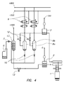
- FIG 4 A more preferred embodiment, which avoids such problems is shown in Fig 4 . where 2 buffer vessels 8a,8b and a dedicated ink supply vessel 13 are available.
- the ink reflow from the shuttle is collected in the ink return header subtank 3 of which the ink level guarded.
- the ink is evacuated as follows.
- the ink return header subtank 3 is connected to the first buffer vessel 8a by opening the appropriate valve 12.
- the first buffer vessel 8a is at -500 mbar, so that ink flows from the ink return header subtank 3 to the first buffer vessel 8a until a desired low level in the ink return header subtank is reached.
- connection to the first buffer vessel 8a is closed by closing the appropriate valve 12.
- This evacuation action can be repeated until the first buffer vessel 8a is full or has reached a desired level.
- excess ink from ink return header subtank 3 is evacuated to the second buffer vessel 8b instead of the first buffer vessel 8a, and in the mean time, by using the appropriate pressure regulating sytem 9, the underpressure of -500 mbar on the first buffer vessel 8a is replaced by a pressure of +800 mbar and the first buffer vessel 8a is emptied into a dedicated ink supply vessel 13, without the use of pumps.
- the second buffer vessel 8b If, after some time, the second buffer vessel 8b is full, a switch from the second to the first buffer vessel 8a occurs, so that excess ink is now evacuated again to the first buffer vessel 8a, and in the mean time the second buffer vessel 8b can be emptied into the ink supply vessel 13.
- This dedicated ink supply vessel 13 is at a constant pressure of +500mbar so ink can be fed at all times to the ink supply header tank 2 which is e.g. at ambient pressure (0 mbar)depending upon the level of the supply header tank 2. This is controlled by an intervening electronically controlled valve 12.
- the step of isolating the ink at low pressure in at least one buffer vessel separated from the high pressure ink supply section preferably comprises the closing of valves in between the connection of the buffer vessel and the high and low pressure ink supply sections by controlled closing of electronically controlled valves 12 or the automatic closing of check valves 10.
- an ink feed pump 7 can be used. This is not a problem as there is less risk for cavitation and a very low risk that air bubbles will reach the printhead 1.
- the circulation pump 4 in the prior art which has to pump the ink from the return header tank 3 to the header feed tank 2 had however to suck ink at a already a low pressure (e.g. -120 mbar), which meant there was quite a risk for cavitation. Therefore, in the present invention, this pump is replaced by the system of ink vessels at fixed and changing pressures.
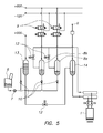
- Fig. 5 includes an additional utility in vessel 14 from which the shuttle is fed.
- Dedicated header supply and reflow tanks are omitted and can be located elswhere on the shuttle itself.
Landscapes
- Ink Jet (AREA)
Priority Applications (4)
| Application Number | Priority Date | Filing Date | Title |
|---|---|---|---|
| EP08102374.9A EP2098372B1 (fr) | 2008-03-07 | 2008-03-07 | Système d'alimentation en encre sans pompe pour imprimante à jet d'encre dotée d'un système de recyclage d'encre |
| PCT/EP2009/001429 WO2009109342A1 (fr) | 2008-03-07 | 2009-02-27 | Système d'alimentation en encre sans pompe, pour imprimante à jet d'encre avec encre |
| CN2009801081323A CN101959690B (zh) | 2008-03-07 | 2009-02-27 | 具有墨水再循环系统的喷墨打印机的无泵墨水供应系统 |
| US12/920,867 US8292385B2 (en) | 2008-03-07 | 2009-02-27 | Ink supply system without pump, for ink jet printer with ink recirculation system |
Applications Claiming Priority (1)
| Application Number | Priority Date | Filing Date | Title |
|---|---|---|---|
| EP08102374.9A EP2098372B1 (fr) | 2008-03-07 | 2008-03-07 | Système d'alimentation en encre sans pompe pour imprimante à jet d'encre dotée d'un système de recyclage d'encre |
Publications (2)
| Publication Number | Publication Date |
|---|---|
| EP2098372A1 true EP2098372A1 (fr) | 2009-09-09 |
| EP2098372B1 EP2098372B1 (fr) | 2017-05-10 |
Family
ID=39615792
Family Applications (1)
| Application Number | Title | Priority Date | Filing Date |
|---|---|---|---|
| EP08102374.9A Not-in-force EP2098372B1 (fr) | 2008-03-07 | 2008-03-07 | Système d'alimentation en encre sans pompe pour imprimante à jet d'encre dotée d'un système de recyclage d'encre |
Country Status (4)
| Country | Link |
|---|---|
| US (1) | US8292385B2 (fr) |
| EP (1) | EP2098372B1 (fr) |
| CN (1) | CN101959690B (fr) |
| WO (1) | WO2009109342A1 (fr) |
Cited By (4)
| Publication number | Priority date | Publication date | Assignee | Title |
|---|---|---|---|---|
| EP2468512A1 (fr) * | 2010-12-27 | 2012-06-27 | Fuji Xerox Co., Ltd. | Appareil de circulation de liquides, support lisible sur ordinateur et appareil de décharge de liquides |
| WO2014206673A1 (fr) | 2013-06-24 | 2014-12-31 | Agfa Graphics Nv | Impression à l'encre à jet d'encre blanche |
| CN110978798A (zh) * | 2019-12-23 | 2020-04-10 | 南通东川数码科技有限公司 | 一种数码打印稳定的打印头正负压循环系统 |
| CN110978799A (zh) * | 2019-12-23 | 2020-04-10 | 南通东川数码科技有限公司 | 一种应用于数码打印稳定的打印头双负压循环系统 |
Families Citing this family (8)
| Publication number | Priority date | Publication date | Assignee | Title |
|---|---|---|---|---|
| CN103738055B (zh) * | 2014-01-02 | 2015-10-14 | 长乐芯聚电子科技研究所 | 便携喷墨打字机 |
| JP6363446B2 (ja) * | 2014-09-22 | 2018-07-25 | 理想科学工業株式会社 | インクジェット印刷装置 |
| CN109070616B (zh) * | 2016-04-29 | 2020-07-28 | 惠普发展公司,有限责任合伙企业 | 选择性地触发流体循环元件 |
| US11110704B2 (en) | 2016-04-29 | 2021-09-07 | Hewlett-Packard Development Company, L.P. | Selectively firing a fluid circulation element |
| CN206856276U (zh) * | 2017-06-30 | 2018-01-09 | 武汉华星光电半导体显示技术有限公司 | 喷墨打印装置 |
| EP3691903B1 (fr) | 2017-12-02 | 2023-03-22 | Hewlett-Packard Development Company, L.P. | Circulation et éjection de fluide |
| JP7251939B2 (ja) * | 2018-09-21 | 2023-04-04 | 株式会社Screenホールディングス | 印刷装置、印刷システム、印刷方法 |
| CN115782407B (zh) * | 2022-11-29 | 2025-08-19 | 华中科技大学鄂州工业技术研究院 | 一种循环供墨系统 |
Citations (4)
| Publication number | Priority date | Publication date | Assignee | Title |
|---|---|---|---|---|
| JPS58219069A (ja) * | 1982-06-15 | 1983-12-20 | Matsushita Electric Ind Co Ltd | インク供給装置 |
| WO2005002860A1 (fr) * | 2003-07-08 | 2005-01-13 | Osiris Technology B.V. | Imprimante a jet d'encre a commande de pression d'encre |
| WO2006064036A1 (fr) | 2004-12-17 | 2006-06-22 | Agfa Graphics Nv | Systeme de circulation d’encre pour impression a jet d’encre |
| US20070268346A1 (en) * | 2006-05-16 | 2007-11-22 | Brother Kogyo Kabushiki Kaisha | Inkjet printers and methods for mounting ink cartridges to inkjet printers |
Family Cites Families (1)
| Publication number | Priority date | Publication date | Assignee | Title |
|---|---|---|---|---|
| US6935729B2 (en) * | 2003-08-28 | 2005-08-30 | International Business Machines Corporation | Ink replenishment system and method for a continuous flow ink jet printer |
-
2008
- 2008-03-07 EP EP08102374.9A patent/EP2098372B1/fr not_active Not-in-force
-
2009
- 2009-02-27 US US12/920,867 patent/US8292385B2/en not_active Expired - Fee Related
- 2009-02-27 WO PCT/EP2009/001429 patent/WO2009109342A1/fr not_active Ceased
- 2009-02-27 CN CN2009801081323A patent/CN101959690B/zh not_active Expired - Fee Related
Patent Citations (4)
| Publication number | Priority date | Publication date | Assignee | Title |
|---|---|---|---|---|
| JPS58219069A (ja) * | 1982-06-15 | 1983-12-20 | Matsushita Electric Ind Co Ltd | インク供給装置 |
| WO2005002860A1 (fr) * | 2003-07-08 | 2005-01-13 | Osiris Technology B.V. | Imprimante a jet d'encre a commande de pression d'encre |
| WO2006064036A1 (fr) | 2004-12-17 | 2006-06-22 | Agfa Graphics Nv | Systeme de circulation d’encre pour impression a jet d’encre |
| US20070268346A1 (en) * | 2006-05-16 | 2007-11-22 | Brother Kogyo Kabushiki Kaisha | Inkjet printers and methods for mounting ink cartridges to inkjet printers |
Cited By (6)
| Publication number | Priority date | Publication date | Assignee | Title |
|---|---|---|---|---|
| EP2468512A1 (fr) * | 2010-12-27 | 2012-06-27 | Fuji Xerox Co., Ltd. | Appareil de circulation de liquides, support lisible sur ordinateur et appareil de décharge de liquides |
| US8449087B2 (en) | 2010-12-27 | 2013-05-28 | Fuji Xerox Co., Ltd. | Liquid circulating apparatus, computer-readable medium, and liquid discharging apparatus |
| WO2014206673A1 (fr) | 2013-06-24 | 2014-12-31 | Agfa Graphics Nv | Impression à l'encre à jet d'encre blanche |
| EP2818327A1 (fr) | 2013-06-24 | 2014-12-31 | Agfa Graphics Nv | Impression d'encre blanche pour jet d'encre |
| CN110978798A (zh) * | 2019-12-23 | 2020-04-10 | 南通东川数码科技有限公司 | 一种数码打印稳定的打印头正负压循环系统 |
| CN110978799A (zh) * | 2019-12-23 | 2020-04-10 | 南通东川数码科技有限公司 | 一种应用于数码打印稳定的打印头双负压循环系统 |
Also Published As
| Publication number | Publication date |
|---|---|
| CN101959690B (zh) | 2013-07-03 |
| EP2098372B1 (fr) | 2017-05-10 |
| WO2009109342A1 (fr) | 2009-09-11 |
| US20110007106A1 (en) | 2011-01-13 |
| CN101959690A (zh) | 2011-01-26 |
| US8292385B2 (en) | 2012-10-23 |
Similar Documents
| Publication | Publication Date | Title |
|---|---|---|
| EP2098372B1 (fr) | Système d'alimentation en encre sans pompe pour imprimante à jet d'encre dotée d'un système de recyclage d'encre | |
| KR101608470B1 (ko) | 잉크분사 인쇄 장치 | |
| US7887148B2 (en) | Method of depriming a printhead with concomitant isolation of ink supply chamber | |
| JP6335165B2 (ja) | 効率的に気泡を除去するように構成されたプリンタ | |
| JP7059041B2 (ja) | インクジェット記録装置 | |
| CN108025556B (zh) | 喷墨印刷装置 | |
| CN112512819B (zh) | 用于打印模块的墨输送系统和输送墨的方法 | |
| JP2011110850A (ja) | 液体循環システム | |
| JP4685370B2 (ja) | インクジェット記録装置におけるインク供給装置 | |
| HK1156578B (en) | Inkjet printing device |
Legal Events
| Date | Code | Title | Description |
|---|---|---|---|
| PUAI | Public reference made under article 153(3) epc to a published international application that has entered the european phase |
Free format text: ORIGINAL CODE: 0009012 |
|
| AK | Designated contracting states |
Kind code of ref document: A1 Designated state(s): AT BE BG CH CY CZ DE DK EE ES FI FR GB GR HR HU IE IS IT LI LT LU LV MC MT NL NO PL PT RO SE SI SK TR |
|
| AX | Request for extension of the european patent |
Extension state: AL BA MK RS |
|
| 17P | Request for examination filed |
Effective date: 20100309 |
|
| AKX | Designation fees paid |
Designated state(s): AT BE BG CH CY CZ DE DK EE ES FI FR GB GR HR HU IE IS IT LI LT LU LV MC MT NL NO PL PT RO SE SI SK TR |
|
| 17Q | First examination report despatched |
Effective date: 20100519 |
|
| GRAP | Despatch of communication of intention to grant a patent |
Free format text: ORIGINAL CODE: EPIDOSNIGR1 |
|
| INTG | Intention to grant announced |
Effective date: 20160914 |
|
| GRAJ | Information related to disapproval of communication of intention to grant by the applicant or resumption of examination proceedings by the epo deleted |
Free format text: ORIGINAL CODE: EPIDOSDIGR1 |
|
| GRAP | Despatch of communication of intention to grant a patent |
Free format text: ORIGINAL CODE: EPIDOSNIGR1 |
|
| INTC | Intention to grant announced (deleted) | ||
| INTG | Intention to grant announced |
Effective date: 20161121 |
|
| GRAS | Grant fee paid |
Free format text: ORIGINAL CODE: EPIDOSNIGR3 |
|
| GRAA | (expected) grant |
Free format text: ORIGINAL CODE: 0009210 |
|
| AK | Designated contracting states |
Kind code of ref document: B1 Designated state(s): AT BE BG CH CY CZ DE DK EE ES FI FR GB GR HR HU IE IS IT LI LT LU LV MC MT NL NO PL PT RO SE SI SK TR |
|
| REG | Reference to a national code |
Ref country code: GB Ref legal event code: FG4D |
|
| REG | Reference to a national code |
Ref country code: AT Ref legal event code: REF Ref document number: 891878 Country of ref document: AT Kind code of ref document: T Effective date: 20170515 Ref country code: CH Ref legal event code: EP |
|
| REG | Reference to a national code |
Ref country code: IE Ref legal event code: FG4D |
|
| REG | Reference to a national code |
Ref country code: DE Ref legal event code: R096 Ref document number: 602008050179 Country of ref document: DE |
|
| REG | Reference to a national code |
Ref country code: NL Ref legal event code: FP |
|
| REG | Reference to a national code |
Ref country code: LT Ref legal event code: MG4D |
|
| REG | Reference to a national code |
Ref country code: AT Ref legal event code: MK05 Ref document number: 891878 Country of ref document: AT Kind code of ref document: T Effective date: 20170510 |
|
| PG25 | Lapsed in a contracting state [announced via postgrant information from national office to epo] |
Ref country code: HR Free format text: LAPSE BECAUSE OF FAILURE TO SUBMIT A TRANSLATION OF THE DESCRIPTION OR TO PAY THE FEE WITHIN THE PRESCRIBED TIME-LIMIT Effective date: 20170510 Ref country code: GR Free format text: LAPSE BECAUSE OF FAILURE TO SUBMIT A TRANSLATION OF THE DESCRIPTION OR TO PAY THE FEE WITHIN THE PRESCRIBED TIME-LIMIT Effective date: 20170811 Ref country code: AT Free format text: LAPSE BECAUSE OF FAILURE TO SUBMIT A TRANSLATION OF THE DESCRIPTION OR TO PAY THE FEE WITHIN THE PRESCRIBED TIME-LIMIT Effective date: 20170510 Ref country code: ES Free format text: LAPSE BECAUSE OF FAILURE TO SUBMIT A TRANSLATION OF THE DESCRIPTION OR TO PAY THE FEE WITHIN THE PRESCRIBED TIME-LIMIT Effective date: 20170510 Ref country code: NO Free format text: LAPSE BECAUSE OF FAILURE TO SUBMIT A TRANSLATION OF THE DESCRIPTION OR TO PAY THE FEE WITHIN THE PRESCRIBED TIME-LIMIT Effective date: 20170810 Ref country code: FI Free format text: LAPSE BECAUSE OF FAILURE TO SUBMIT A TRANSLATION OF THE DESCRIPTION OR TO PAY THE FEE WITHIN THE PRESCRIBED TIME-LIMIT Effective date: 20170510 Ref country code: LT Free format text: LAPSE BECAUSE OF FAILURE TO SUBMIT A TRANSLATION OF THE DESCRIPTION OR TO PAY THE FEE WITHIN THE PRESCRIBED TIME-LIMIT Effective date: 20170510 |
|
| PG25 | Lapsed in a contracting state [announced via postgrant information from national office to epo] |
Ref country code: LV Free format text: LAPSE BECAUSE OF FAILURE TO SUBMIT A TRANSLATION OF THE DESCRIPTION OR TO PAY THE FEE WITHIN THE PRESCRIBED TIME-LIMIT Effective date: 20170510 Ref country code: BG Free format text: LAPSE BECAUSE OF FAILURE TO SUBMIT A TRANSLATION OF THE DESCRIPTION OR TO PAY THE FEE WITHIN THE PRESCRIBED TIME-LIMIT Effective date: 20170810 Ref country code: SE Free format text: LAPSE BECAUSE OF FAILURE TO SUBMIT A TRANSLATION OF THE DESCRIPTION OR TO PAY THE FEE WITHIN THE PRESCRIBED TIME-LIMIT Effective date: 20170510 Ref country code: PL Free format text: LAPSE BECAUSE OF FAILURE TO SUBMIT A TRANSLATION OF THE DESCRIPTION OR TO PAY THE FEE WITHIN THE PRESCRIBED TIME-LIMIT Effective date: 20170510 Ref country code: IS Free format text: LAPSE BECAUSE OF FAILURE TO SUBMIT A TRANSLATION OF THE DESCRIPTION OR TO PAY THE FEE WITHIN THE PRESCRIBED TIME-LIMIT Effective date: 20170910 |
|
| RAP2 | Party data changed (patent owner data changed or rights of a patent transferred) |
Owner name: AGFA NV |
|
| REG | Reference to a national code |
Ref country code: DE Ref legal event code: R081 Ref document number: 602008050179 Country of ref document: DE Owner name: AGFA NV, BE Free format text: FORMER OWNER: AGFA GRAPHICS N.V., MORTSEL, BE |
|
| PG25 | Lapsed in a contracting state [announced via postgrant information from national office to epo] |
Ref country code: EE Free format text: LAPSE BECAUSE OF FAILURE TO SUBMIT A TRANSLATION OF THE DESCRIPTION OR TO PAY THE FEE WITHIN THE PRESCRIBED TIME-LIMIT Effective date: 20170510 Ref country code: DK Free format text: LAPSE BECAUSE OF FAILURE TO SUBMIT A TRANSLATION OF THE DESCRIPTION OR TO PAY THE FEE WITHIN THE PRESCRIBED TIME-LIMIT Effective date: 20170510 Ref country code: SK Free format text: LAPSE BECAUSE OF FAILURE TO SUBMIT A TRANSLATION OF THE DESCRIPTION OR TO PAY THE FEE WITHIN THE PRESCRIBED TIME-LIMIT Effective date: 20170510 Ref country code: CZ Free format text: LAPSE BECAUSE OF FAILURE TO SUBMIT A TRANSLATION OF THE DESCRIPTION OR TO PAY THE FEE WITHIN THE PRESCRIBED TIME-LIMIT Effective date: 20170510 Ref country code: RO Free format text: LAPSE BECAUSE OF FAILURE TO SUBMIT A TRANSLATION OF THE DESCRIPTION OR TO PAY THE FEE WITHIN THE PRESCRIBED TIME-LIMIT Effective date: 20170510 |
|
| REG | Reference to a national code |
Ref country code: FR Ref legal event code: PLFP Year of fee payment: 11 |
|
| REG | Reference to a national code |
Ref country code: DE Ref legal event code: R097 Ref document number: 602008050179 Country of ref document: DE |
|
| PG25 | Lapsed in a contracting state [announced via postgrant information from national office to epo] |
Ref country code: IT Free format text: LAPSE BECAUSE OF FAILURE TO SUBMIT A TRANSLATION OF THE DESCRIPTION OR TO PAY THE FEE WITHIN THE PRESCRIBED TIME-LIMIT Effective date: 20170510 |
|
| REG | Reference to a national code |
Ref country code: NL Ref legal event code: HC Owner name: AGFA NV; BE Free format text: DETAILS ASSIGNMENT: CHANGE OF OWNER(S), CHANGE OF OWNER(S) NAME; FORMER OWNER NAME: AGFA GRAPHICS N.V. Effective date: 20180126 |
|
| PLBE | No opposition filed within time limit |
Free format text: ORIGINAL CODE: 0009261 |
|
| STAA | Information on the status of an ep patent application or granted ep patent |
Free format text: STATUS: NO OPPOSITION FILED WITHIN TIME LIMIT |
|
| 26N | No opposition filed |
Effective date: 20180213 |
|
| PG25 | Lapsed in a contracting state [announced via postgrant information from national office to epo] |
Ref country code: SI Free format text: LAPSE BECAUSE OF FAILURE TO SUBMIT A TRANSLATION OF THE DESCRIPTION OR TO PAY THE FEE WITHIN THE PRESCRIBED TIME-LIMIT Effective date: 20170510 |
|
| REG | Reference to a national code |
Ref country code: FR Ref legal event code: CD Owner name: AGFA NV, BE Effective date: 20180628 |
|
| REG | Reference to a national code |
Ref country code: CH Ref legal event code: PL |
|
| PG25 | Lapsed in a contracting state [announced via postgrant information from national office to epo] |
Ref country code: MC Free format text: LAPSE BECAUSE OF FAILURE TO SUBMIT A TRANSLATION OF THE DESCRIPTION OR TO PAY THE FEE WITHIN THE PRESCRIBED TIME-LIMIT Effective date: 20170510 |
|
| REG | Reference to a national code |
Ref country code: BE Ref legal event code: MM Effective date: 20180331 |
|
| REG | Reference to a national code |
Ref country code: IE Ref legal event code: MM4A |
|
| PG25 | Lapsed in a contracting state [announced via postgrant information from national office to epo] |
Ref country code: LU Free format text: LAPSE BECAUSE OF NON-PAYMENT OF DUE FEES Effective date: 20180307 |
|
| PG25 | Lapsed in a contracting state [announced via postgrant information from national office to epo] |
Ref country code: IE Free format text: LAPSE BECAUSE OF NON-PAYMENT OF DUE FEES Effective date: 20180307 |
|
| PG25 | Lapsed in a contracting state [announced via postgrant information from national office to epo] |
Ref country code: LI Free format text: LAPSE BECAUSE OF NON-PAYMENT OF DUE FEES Effective date: 20180331 Ref country code: BE Free format text: LAPSE BECAUSE OF NON-PAYMENT OF DUE FEES Effective date: 20180331 Ref country code: CH Free format text: LAPSE BECAUSE OF NON-PAYMENT OF DUE FEES Effective date: 20180331 |
|
| PG25 | Lapsed in a contracting state [announced via postgrant information from national office to epo] |
Ref country code: MT Free format text: LAPSE BECAUSE OF NON-PAYMENT OF DUE FEES Effective date: 20180307 |
|
| PG25 | Lapsed in a contracting state [announced via postgrant information from national office to epo] |
Ref country code: TR Free format text: LAPSE BECAUSE OF FAILURE TO SUBMIT A TRANSLATION OF THE DESCRIPTION OR TO PAY THE FEE WITHIN THE PRESCRIBED TIME-LIMIT Effective date: 20170510 |
|
| PG25 | Lapsed in a contracting state [announced via postgrant information from national office to epo] |
Ref country code: PT Free format text: LAPSE BECAUSE OF FAILURE TO SUBMIT A TRANSLATION OF THE DESCRIPTION OR TO PAY THE FEE WITHIN THE PRESCRIBED TIME-LIMIT Effective date: 20170510 Ref country code: HU Free format text: LAPSE BECAUSE OF FAILURE TO SUBMIT A TRANSLATION OF THE DESCRIPTION OR TO PAY THE FEE WITHIN THE PRESCRIBED TIME-LIMIT; INVALID AB INITIO Effective date: 20080307 |
|
| PG25 | Lapsed in a contracting state [announced via postgrant information from national office to epo] |
Ref country code: CY Free format text: LAPSE BECAUSE OF FAILURE TO SUBMIT A TRANSLATION OF THE DESCRIPTION OR TO PAY THE FEE WITHIN THE PRESCRIBED TIME-LIMIT Effective date: 20170510 |
|
| PGFP | Annual fee paid to national office [announced via postgrant information from national office to epo] |
Ref country code: FR Payment date: 20210225 Year of fee payment: 14 Ref country code: NL Payment date: 20210224 Year of fee payment: 14 |
|
| PGFP | Annual fee paid to national office [announced via postgrant information from national office to epo] |
Ref country code: GB Payment date: 20210225 Year of fee payment: 14 Ref country code: DE Payment date: 20210225 Year of fee payment: 14 |
|
| REG | Reference to a national code |
Ref country code: DE Ref legal event code: R119 Ref document number: 602008050179 Country of ref document: DE |
|
| REG | Reference to a national code |
Ref country code: NL Ref legal event code: MM Effective date: 20220401 |
|
| GBPC | Gb: european patent ceased through non-payment of renewal fee |
Effective date: 20220307 |
|
| PG25 | Lapsed in a contracting state [announced via postgrant information from national office to epo] |
Ref country code: NL Free format text: LAPSE BECAUSE OF NON-PAYMENT OF DUE FEES Effective date: 20220401 Ref country code: GB Free format text: LAPSE BECAUSE OF NON-PAYMENT OF DUE FEES Effective date: 20220307 Ref country code: FR Free format text: LAPSE BECAUSE OF NON-PAYMENT OF DUE FEES Effective date: 20220331 Ref country code: DE Free format text: LAPSE BECAUSE OF NON-PAYMENT OF DUE FEES Effective date: 20221001 |