EP2098441B1 - Dispositif de commande d'air pour véhicule - Google Patents
Dispositif de commande d'air pour véhicule Download PDFInfo
- Publication number
- EP2098441B1 EP2098441B1 EP09007885A EP09007885A EP2098441B1 EP 2098441 B1 EP2098441 B1 EP 2098441B1 EP 09007885 A EP09007885 A EP 09007885A EP 09007885 A EP09007885 A EP 09007885A EP 2098441 B1 EP2098441 B1 EP 2098441B1
- Authority
- EP
- European Patent Office
- Prior art keywords
- spoiler element
- spoiler
- vehicle
- air conduction
- deployment mechanism
- Prior art date
- Legal status (The legal status is an assumption and is not a legal conclusion. Google has not performed a legal analysis and makes no representation as to the accuracy of the status listed.)
- Not-in-force
Links
- 230000007246 mechanism Effects 0.000 claims description 18
- 230000008878 coupling Effects 0.000 claims description 7
- 238000010168 coupling process Methods 0.000 claims description 7
- 238000005859 coupling reaction Methods 0.000 claims description 7
- 230000004913 activation Effects 0.000 claims 2
- 230000008859 change Effects 0.000 description 5
- 230000000694 effects Effects 0.000 description 2
- 230000001747 exhibiting effect Effects 0.000 description 2
- 239000013641 positive control Substances 0.000 description 2
- 230000006978 adaptation Effects 0.000 description 1
- 238000006073 displacement reaction Methods 0.000 description 1
- 230000004044 response Effects 0.000 description 1
Images

Classifications
-
- B—PERFORMING OPERATIONS; TRANSPORTING
- B62—LAND VEHICLES FOR TRAVELLING OTHERWISE THAN ON RAILS
- B62D—MOTOR VEHICLES; TRAILERS
- B62D35/00—Vehicle bodies characterised by streamlining
- B62D35/007—Rear spoilers
-
- Y—GENERAL TAGGING OF NEW TECHNOLOGICAL DEVELOPMENTS; GENERAL TAGGING OF CROSS-SECTIONAL TECHNOLOGIES SPANNING OVER SEVERAL SECTIONS OF THE IPC; TECHNICAL SUBJECTS COVERED BY FORMER USPC CROSS-REFERENCE ART COLLECTIONS [XRACs] AND DIGESTS
- Y02—TECHNOLOGIES OR APPLICATIONS FOR MITIGATION OR ADAPTATION AGAINST CLIMATE CHANGE
- Y02T—CLIMATE CHANGE MITIGATION TECHNOLOGIES RELATED TO TRANSPORTATION
- Y02T10/00—Road transport of goods or passengers
- Y02T10/80—Technologies aiming to reduce greenhouse gasses emissions common to all road transportation technologies
- Y02T10/82—Elements for improving aerodynamics
Definitions
- the invention relates to a spoiler device for a vehicle according to the preamble of patent claim 1.
- Such a spoiler is from the document WO 2006/119746 A1 and comprises a spoiler element which extends essentially in the vehicle transverse direction and which can be moved from a retracted rest position into a maximally extended stroke position by means of a deployment kinematics preceding a movement path.
- the spoiler element is provided with an adjusting device, upon actuation of which the angle of attack of the spoiler element with respect to the vehicle body changes.
- the tilting kinematics includes a four-bar mechanism with two arms, each of which is articulated to the vehicle body with one end. One of the links is driven by means of a drive device.
- the spoiler device comprises a spoiler element extending essentially in the vehicle transverse direction, which can be moved by means of a pop-up kinematics from a retracted rest position, in which it is received, for example, by a body recess, and a maximally extended stroke position, in which it is aerodynamically effective.
- a pop-up kinematics of a rear spoiler comprises in a known manner, for example, linearly movable lifting cylinder or also hinged on both sides of the spoiler element four-bar linkages, which dictate the Ausstellterrorism the spoiler element.
- At the one Linear movement predetermining lifting cylinders is the angle of attack of the spoiler element relative to the vehicle body or the lifting cylinders over the entire predetermined by the Ausstellkinematik trajectory constant. It is not possible to influence the aerodynamic effect of the spoiler element by changing its angle of attack.
- the angle of attack of the spoiler element relative to the vehicle body is determined by the interpretation of the handlebars of the four-bar linkages. An independent adaptation of the angle of attack of the spoiler element is not possible.
- the invention has for its object to provide a spoiler for a vehicle, which can be adjusted in an optimized manner to the respective present requirements for the aerodynamics of the vehicle in question compared to the prior art described above.
- the essence of the invention is therefore that an adjusting device is provided, by means of which the angle of attack of the spoiler element relative to the Ausstellkinematik is adjustable.
- the position of the spoiler element or Spoilerblatts is therefore changeable by the addition to the Ausstellkinematik adjustment and thus adaptable to the respective requirements, so that the aerodynamics and the driving characteristics of the vehicle in question can be improved by changing the angle of the spoiler element.
- the tilting kinematics comprises a four-bar mechanism with two links, one of which is driven by means of a drive device and which are each articulated at one end fixed to the body.
- Either a positive control for actuating the adjusting device for the angle of attack of the spoiler element can take place or a separate drive can be provided for actuating the adjusting device.
- the two links can be articulated with their respective second ends to a coupling element on which the spoiler element is pivotally mounted via a steering lever, which with a control handlebar is connected, the end facing away from the steering lever forms a body-mounted base.
- the control handle Upon actuation of the four-bar mechanism, the control handle thus exerts a moment on the steering lever, whereby the angle of attack of the spoiler element is changed relative to the coupling element.
- the foot is preferably carried out adjustable.
- the body-hinged end of the non-driven arm of the four-bar mechanism by means of a second drive means displaced, so that at an actuation of the second drive means changes the angle of attack of the spoiler element.
- the adjusting device for adjusting the angle of attack of the spoiler element operates in response to the stroke of the spoiler element, being forcibly controlled by the Ausstellkinematik. Accordingly, there is always a change in the angle of attack of the spoiler element with respect to the tilting kinematics upon actuation of the tilting kinematics.
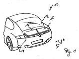
- a motor vehicle 10 is shown, the rear side below a rear window 12 has a rear spoiler performing air guide.
- the spoiler 14 comprises a spoiler blade or element 16 which extends essentially in the vehicle transverse direction and which can be moved by means of a pop-up kinematics arranged on both sides between a rest position arranged in a rear-side body recess 18 and an exposed operating position which represents an aerodynamically effective position.
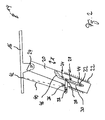
- the spoiler element 16 is pivotally connected to the lifting cylinder 20 via a joint 24 whose pivot axis extends in the vehicle transverse direction.
- a control lever 28 designed as an angle is articulated on the lifting cylinder 20 in a region remote from the joint 24 via a joint 26, one leg 30 of which has a guide pin 32 in its end region facing away from the joint 26, which moves in a guide rail 34 fixed to the body is.
- the second leg 36 of the control lever 28 has in its end remote from the joint 26 an adjustable in the direction of the axis of the leg 36 pivot point 38 for a control linkage 40, which connects the leg 36 of the control lever 28 with the spoiler element 16.
- a pivot point 42 is formed on the spoiler element 16.
- the slide track 34 has a parallel to the direction of movement X of the lifting cylinder 20 aligned lower portion 44, which merges into a bent and inclined with respect to the movement direction X of the lifting cylinder 20 adjusting portion 46 above.
- spoiler 14 operates in the manner described below.
- the ratio between the stroke and the pivoting angle of the spoiler element 16 set by the adjusting section 46 can be changed by changing the articulation point 38 of the control linkage 40 on the leg 36 of the control lever 28.
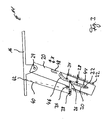
- FIG. 3 illustrated embodiment of a spoiler 14 'differs from the one after Fig. 2 merely in that adjoining the curved adjustment section 46 of the guide track 34 above a likewise arranged parallel to the direction of movement of the lifting cylinder 20 locking portion 48, so that it can be achieved that the adjustment of the control rod 40 and the control lever 28 adjustment for the angle of the spoiler element 16 is locked when the guide pin 32 of the control lever 28 disposed in the locking portion 48 is. This prevents inadvertent pivoting of the spoiler element 16 relative to the lifting cylinder 20.
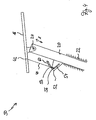
- FIG. 4 an alternative embodiment of an air guiding device 50 is shown, which according to the embodiments described above, a spoiler element 16 which is articulated via a hinge 24 to a lifting cylinder 20 which is movable to extend or retract the spoiler element 16 according to a double arrow X.
- the lifting cylinder 20 has a protruding in the radial direction tab 52 on which a hubzylinderfeste guideway 54 is formed, which is inclined relative to the axis of the lifting cylinder 20.
- a guide pin 56 is guided, which is formed at one end of a control linkage 40, which is articulated with the guide pin 56 opposite end via a pivot point 42 on the spoiler element 16.
- the pivot point 42 is changeable or adjustable.
- the spoiler 50 has a body-mounted slide track 58, which has a lower, parallel to the axis and thus to the direction of movement X of the lifting cylinder 20 aligned portion at the top of a relative to the axis of the lifting cylinder 20 inclined and opposite to the guide track 54 aligned Adjustment 58 connects.
- the guide pin 56 which is formed at the lower end of the control linkage 40, also guided in the slide track 58, wherein the guide in the adjustment 60 causes pivoting and thus changing the angle of the spoiler element 16.
- an air guiding device 70 which also has a spoiler element 16 which can be moved from a retracted rest position into an extended stroke position or operative position.
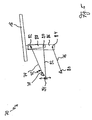
- the spoiler 70 has a pop-up kinematics, which is formed with a four-bar linkage 72, which has two links 74 and 76, which are each articulated at one end via a hinge 78 and 80 fixed to the body. With their hinges 78 and 80 facing away from the handlebars 74 and 76 respectively hinged via a hinge 82 and 84 on a coupling element 86, on which in turn via a steering lever 88, the spoiler element 16 is pivotally mounted.
- the pivot point of the link 74 and that of the steering lever 88 on the coupling element 86 lie on a common axis.
- a control link 92 is fastened via a further joint 90, forming with its ends facing away from the coupling element 86 a foot point 94 fixed to the body, which is adjustable to change the ratio of stroke to angle of attack of the spoiler element 16.
- the spoiler 70 operates in the manner described below.
- one of the links 74 and 76 of the four-bar linkage 72 is driven so that the spoiler element 16 is moved into its deployed operative position.
- the control link 92 exerts a force on the steering lever 88, so that changes the angle of attack of the spoiler element 16 by pivoting the steering lever 88 about its pivot axis.
- the links 74 and 76 pivoted clockwise about the axes of the joints 78 and 80, so that the handlebar 92 exerts a pulling movement on the steering lever 88 and the spoiler element 16 is also pivoted clockwise.
- Fig. 6 an air guiding device 100 is shown, which also has a spoiler element 16 which is pivotable between a lowered rest position and a flared operating position.
- the spoiler 100 also has a four-bar linkage mechanism comprising two links 102 and 104, which are each hinged at one end to the spoiler element 16 and are articulated body-tight with their respective other end.
- the link 102 is connected to a pivoting of the four-bar mechanism causing drive motor 106, which causes the issuing of the spoiler element 16.
- the body-mounted pivot point 108 of the non-driven arm 104 is connected to a second drive motor 110, which can change the position of the pivot point 108.
Landscapes
- Engineering & Computer Science (AREA)
- Chemical & Material Sciences (AREA)
- Combustion & Propulsion (AREA)
- Transportation (AREA)
- Mechanical Engineering (AREA)
- Superstructure Of Vehicle (AREA)
- Power-Operated Mechanisms For Wings (AREA)
- Lighting Device Outwards From Vehicle And Optical Signal (AREA)
- Platform Screen Doors And Railroad Systems (AREA)
- Window Of Vehicle (AREA)
- Motorcycle And Bicycle Frame (AREA)
- Mechanical Control Devices (AREA)
Claims (4)
- Dispositif de guidage d'air pour un véhicule, comprenant un élément déflecteur (16) s'étendant essentiellement dans la direction transversale du véhicule, ainsi qu'une cinématique d'orientation prédéfinissant une voie de déplacement, au moyen de laquelle l'élément déflecteur (16) peut être déplacé d'une position de repos rentrée dans une position de levage déployée au maximum, l'élément déflecteur (16) étant pourvu d'un dispositif de réglage, dont l'actionnement modifie l'angle d'inclinaison de l'élément déflecteur (16) par rapport à la carrosserie du véhicule, la cinématique d'orientation comprenant au moins un mécanisme à quadrilatère articulé (72) avec deux bras oscillants (74, 76) dont l'un est entraîné au moyen d'un dispositif d'entraînement et lesquels sont chacun articulés fixement à la carrosserie par une extrémité, caractérisé en ce que les deux bras oscillants (74, 76) sont articulés par leur deuxième extrémité respective à un élément d'accouplement (86), sur lequel l'élément déflecteur (16) est monté de manière pivotante par le biais d'un levier de direction (88) qui est connecté à un bras de commande (92) dont l'extrémité opposée au levier de direction (88) forme un point de base (94) fixé à la carrosserie.
- Dispositif de guidage d'air selon la revendication 1, caractérisé en ce que le point de base (94) est réglable.
- Dispositif de guidage d'air pour un véhicule, comprenant un élément déflecteur (16) s'étendant essentiellement dans la direction transversale du véhicule, ainsi qu'une cinématique d'orientation prédéfinissant une voie de déplacement, au moyen de laquelle l'élément déflecteur (16) peut être déplacé d'une position de repos rentrée dans une position de levage déployée au maximum, l'élément déflecteur (16) étant pourvu d'un dispositif de réglage, dont l'actionnement modifie l'angle d'inclinaison de l'élément déflecteur (16) par rapport à la carrosserie du véhicule, la cinématique d'orientation comprenant au moins un mécanisme à quadrilatère articulé avec deux bras oscillants (102, 104) dont l'un est entraîné au moyen d'un dispositif d'entraînement (106) et lesquels sont chacun articulés fixement à la carrosserie par une extrémité, caractérisé en ce que l'extrémité du bras oscillant non entraîné (104), du mécanisme à quadrilatère articulé, qui est articulée fixement à la carrosserie, peut être déplacée au moyen d'un deuxième dispositif d'entraînement (110), de sorte que l'angle d'inclinaison de l'élément déflecteur (16) soit modifié.
- Dispositif de guidage d'air selon la revendication 1 ou 3, caractérisé en ce que le dispositif de réglage fonctionne en fonction du levage de l'élément déflecteur (16) et est commandé par force par la cinématique d'orientation.
Applications Claiming Priority (2)
| Application Number | Priority Date | Filing Date | Title |
|---|---|---|---|
| DE102006059724A DE102006059724B4 (de) | 2006-12-18 | 2006-12-18 | Luftleitvorrichtung für ein Fahrzeug |
| EP07023671A EP1935765B1 (fr) | 2006-12-18 | 2007-12-06 | Dispositif de commande d'air pour véhicule |
Related Parent Applications (2)
| Application Number | Title | Priority Date | Filing Date |
|---|---|---|---|
| EP07023671.6 Division | 2007-12-06 | ||
| EP07023671A Division EP1935765B1 (fr) | 2006-12-18 | 2007-12-06 | Dispositif de commande d'air pour véhicule |
Publications (3)
| Publication Number | Publication Date |
|---|---|
| EP2098441A2 EP2098441A2 (fr) | 2009-09-09 |
| EP2098441A3 EP2098441A3 (fr) | 2009-10-14 |
| EP2098441B1 true EP2098441B1 (fr) | 2010-10-27 |
Family
ID=39233000
Family Applications (2)
| Application Number | Title | Priority Date | Filing Date |
|---|---|---|---|
| EP09007885A Not-in-force EP2098441B1 (fr) | 2006-12-18 | 2007-12-06 | Dispositif de commande d'air pour véhicule |
| EP07023671A Not-in-force EP1935765B1 (fr) | 2006-12-18 | 2007-12-06 | Dispositif de commande d'air pour véhicule |
Family Applications After (1)
| Application Number | Title | Priority Date | Filing Date |
|---|---|---|---|
| EP07023671A Not-in-force EP1935765B1 (fr) | 2006-12-18 | 2007-12-06 | Dispositif de commande d'air pour véhicule |
Country Status (4)
| Country | Link |
|---|---|
| US (1) | US7578543B2 (fr) |
| EP (2) | EP2098441B1 (fr) |
| JP (1) | JP2008150034A (fr) |
| DE (3) | DE102006059724B4 (fr) |
Cited By (2)
| Publication number | Priority date | Publication date | Assignee | Title |
|---|---|---|---|---|
| WO2015000538A1 (fr) | 2013-07-04 | 2015-01-08 | Wabco Europe Bvba | Dispositif formant becquet arrière pour véhicule automobile |
| DE102018213034B4 (de) * | 2018-08-03 | 2025-08-21 | Bayerische Motoren Werke Aktiengesellschaft | Kraftfahrzeug mit einer Luftleiteinrichtung für eine Fahrzeugfront |
Families Citing this family (29)
| Publication number | Priority date | Publication date | Assignee | Title |
|---|---|---|---|---|
| USD249623S (en) * | 1975-10-24 | 1978-09-26 | Sharp Kabushiki Kaisha | Electronic cooking range |
| DE102005021832A1 (de) * | 2005-05-11 | 2006-11-23 | Webasto Ag | Luftleitvorrichtung eines Fahrzeugs |
| US7380868B2 (en) | 2005-06-29 | 2008-06-03 | Thomas Scott Breidenbach | Aerodynamic drag reducing apparatus |
| DE102006014258A1 (de) * | 2006-03-28 | 2007-10-04 | Dr.Ing.H.C. F. Porsche Ag | Luftleitvorrichtung für ein Fahrzeug |
| GB0808349D0 (en) * | 2008-05-09 | 2008-06-18 | Airbus Uk Ltd | Spoiler deployment mechanism |
| DE102008024892B4 (de) | 2008-05-16 | 2019-06-19 | Dr. Ing. H.C. F. Porsche Aktiengesellschaft | Luftleiteinrichtung |
| DE102008024701B4 (de) * | 2008-05-21 | 2021-02-11 | Dr. Ing. H.C. F. Porsche Aktiengesellschaft | Heckklappe und Kraftfahrzeug |
| USD609617S1 (en) * | 2008-08-12 | 2010-02-09 | Dr. Ing. H.C. F. Porsche Aktiengesellschaft | Automobile spoiler |
| DE102008062150A1 (de) * | 2008-12-16 | 2010-06-24 | Dr. Ing. H.C. F. Porsche Aktiengesellschaft | Verstell-Vorrichtung |
| DE102010004560B4 (de) * | 2010-01-14 | 2024-09-12 | Dr. Ing. H.C. F. Porsche Aktiengesellschaft | Personenkraftfahrzeug mit heckseitiger Luftleitvorrichtung |
| DE102011053831B4 (de) * | 2011-09-21 | 2024-07-04 | Dr. Ing. H.C. F. Porsche Aktiengesellschaft | Heckspoiler mit einer Kühleinrichtung für ein Kraftfahrzeug |
| DE102014208278A1 (de) * | 2014-05-02 | 2015-11-05 | Suspa Gmbh | Führungs-Vorrichtung zum geführten Verlagern eines beweglichen Karosserieelements, Verlagerungs-Einrichtung umfassend eine derartige Führungs-Vorrichtung sowie Kraftfahrzeug mit einer derartigen Verlagerungs-Einrichtung |
| US9575461B2 (en) * | 2014-08-07 | 2017-02-21 | Canon Kabushiki Kaisha | Process cartridge and image forming method using toner having properties for high image quality |
| KR20160054259A (ko) * | 2014-11-06 | 2016-05-16 | 현대자동차주식회사 | 자동차의 가변 스포일러 장치 |
| GB2533576B (en) * | 2014-12-22 | 2021-01-20 | Marchantcain Design Ltd | Actuator |
| US9950751B2 (en) * | 2015-09-25 | 2018-04-24 | GM Global Technology Operations LLC | Aerodynamic system and method for diagnosing the aerodynamic system and verify downforce estimation based on electric motor current |
| JP6311691B2 (ja) * | 2015-10-26 | 2018-04-18 | マツダ株式会社 | 車両の後部構造 |
| GB2545402B (en) | 2015-12-09 | 2020-01-08 | Jaguar Land Rover Ltd | Motor vehicle active wing apparatus and method |
| GB2545400B (en) | 2015-12-09 | 2020-05-20 | Jaguar Land Rover Ltd | Motor vehicle active wing apparatus and method |
| GB2545401B (en) | 2015-12-09 | 2020-01-08 | Jaguar Land Rover Ltd | Motor vehicle active wing apparatus and method |
| FR3045554B1 (fr) * | 2015-12-22 | 2018-02-02 | Compagnie Plastic Omnium | Dispositif de manoeuvre d'un volet aerodynamique |
| US9776675B1 (en) * | 2016-05-18 | 2017-10-03 | GM Global Technology Operations LLC | Vehicle wing with position-maintaining endplates |
| KR101836736B1 (ko) * | 2016-11-14 | 2018-03-09 | 현대자동차주식회사 | Rv 차량의 스포일러 장치 |
| USD891333S1 (en) * | 2018-04-13 | 2020-07-28 | Dr. Ing. H.C. F. Porsche Aktiengesellschaft | Spoiler for motor vehicle |
| CN109552436A (zh) * | 2018-11-21 | 2019-04-02 | 浙江工业大学 | 一种电动赛车可调式尾翼 |
| DE102019128305B3 (de) * | 2019-10-21 | 2021-04-01 | Dr. Ing. H.C. F. Porsche Aktiengesellschaft | Antriebsvorrichtung für ein verstellbares Luftleitelement eines Kraftfahrzeugs und Luftleitvorrichtung |
| DE102019128309B3 (de) * | 2019-10-21 | 2021-02-04 | Dr. Ing. H.C. F. Porsche Aktiengesellschaft | Antriebsvorrichtung für ein verstellbares Luftleitelement eines Kraftfahrzeugs und eine Luftleitvorrichtung |
| USD944334S1 (en) * | 2021-09-15 | 2022-02-22 | Traxxas Lp | Model vehicle body |
| IT202200015267A1 (it) * | 2022-07-20 | 2024-01-20 | Ferrari Spa | Gruppo ala mobile per un veicolo stradale, metodo di controllo di un'ala mobile per un veicolo stradale e relativo veicolo stradale |
Family Cites Families (25)
| Publication number | Priority date | Publication date | Assignee | Title |
|---|---|---|---|---|
| JPS60209369A (ja) * | 1984-04-04 | 1985-10-21 | Nissan Motor Co Ltd | 自動車のスポイラ制御装置 |
| JP2580262B2 (ja) * | 1988-06-24 | 1997-02-12 | 日産自動車株式会社 | 自動車のリアスポイラ装置 |
| EP0367230B1 (fr) * | 1988-10-31 | 1995-05-17 | Ohi Seisakusho Co., Ltd. | Dispositif de volet aérodynamique |
| JPH0621837Y2 (ja) * | 1989-06-21 | 1994-06-08 | 株式会社大井製作所 | リヤスポイラ装置 |
| DE4009385A1 (de) * | 1990-03-23 | 1991-09-26 | Porsche Ag | Kraftfahrzeug, insbesondere personenwagen mit einer im heckbereich angeordneten luftleitvorrichtung |
| DE4014380A1 (de) * | 1990-05-04 | 1991-11-07 | Porsche Ag | Kraftfahrzeug, insbesondere personenwagen mit einer im heckbereich angeordneten luftleitvorrichtung |
| DE4207658C2 (de) * | 1992-03-11 | 1994-07-21 | Daimler Benz Ag | Strömungsleitvorrichtung für ein Fahrzeug |
| DE4305115A1 (de) * | 1993-02-19 | 1994-08-25 | Porsche Ag | Luftleitvorrichtung |
| FR2728535A1 (fr) * | 1994-12-26 | 1996-06-28 | Aerospatiale | Aerofrein a fente variable pour voilure d'aeronef |
| DE29909639U1 (de) * | 1999-06-01 | 1999-08-05 | HS Products AG Systemtechnik und Produktmanagement, 82152 Krailling | Vorrichtung zum Verstellen eines an einem Fahrzeug vorgesehenen Spoilers |
| US6565145B2 (en) * | 2000-12-01 | 2003-05-20 | Btr Robotic Limited | Adjustable automotive airfoil |
| US6520564B1 (en) * | 2002-01-16 | 2003-02-18 | Yet Chang Mobile Goods Co., Ltd. | Air flow guiding board structure of an automobile |
| DE10222082A1 (de) * | 2002-05-17 | 2003-11-27 | Bayerische Motoren Werke Ag | Strömungsleitvorrichtung für ein Fahrzeug |
| US20040256885A1 (en) * | 2003-03-10 | 2004-12-23 | Bui Le Trong | Rear spoiler with motorized vertical and angle adjustability |
| US6805399B1 (en) * | 2003-09-26 | 2004-10-19 | Allan L. Brown | Vehicle momentum force actuated braking aerostabilizer |
| US7052074B2 (en) * | 2003-10-03 | 2006-05-30 | All Sales Manufacturing, Inc. | Angularly adjustable illuminated spoiler |
| WO2005058677A1 (fr) * | 2003-12-17 | 2005-06-30 | Prospective Concepts Ag | Dispositif pour deplacer un dispositif de deflexion d'air |
| FR2867442B1 (fr) | 2004-03-09 | 2006-05-05 | Renault Sas | Vehicule automobile comportant un aileron escamotable |
| DE102004030571B4 (de) * | 2004-06-24 | 2007-03-08 | Webasto Ag | Luftleitvorrichtung für ein Kraftfahrzeug |
| FR2874579B1 (fr) * | 2004-08-31 | 2006-10-13 | Peugeot Citroen Automobiles Sa | Dispositif aerodynamique perfectionne avec aileron et son implantation sur vehicule automobile |
| DE102004045662B4 (de) * | 2004-09-18 | 2008-10-30 | Jost-Werke Gmbh | Verstellvorrichtung, Steuergerät und Vorrichtung zur Verringerung des Luftwiderstandes eines Sattelzuges |
| DE102005008001A1 (de) * | 2005-02-22 | 2006-08-31 | Dr.Ing.H.C. F. Porsche Ag | Heckseitige Luftleitvorrichtung für ein Kraftfahrzeug |
| DE102005021832A1 (de) * | 2005-05-11 | 2006-11-23 | Webasto Ag | Luftleitvorrichtung eines Fahrzeugs |
| US20080061596A1 (en) * | 2006-09-08 | 2008-03-13 | Brown Allan L | Vehicle low cost braking aerostabilizer |
| US7641262B2 (en) * | 2006-10-19 | 2010-01-05 | Nusbaum Howard G | Retractable air deflection apparatus for reduction of vehicular air drag |
-
2006
- 2006-12-18 DE DE102006059724A patent/DE102006059724B4/de not_active Expired - Fee Related
-
2007
- 2007-12-06 EP EP09007885A patent/EP2098441B1/fr not_active Not-in-force
- 2007-12-06 DE DE502007005497T patent/DE502007005497D1/de active Active
- 2007-12-06 EP EP07023671A patent/EP1935765B1/fr not_active Not-in-force
- 2007-12-06 DE DE502007002670T patent/DE502007002670D1/de active Active
- 2007-12-18 US US11/958,505 patent/US7578543B2/en not_active Expired - Fee Related
- 2007-12-18 JP JP2007326198A patent/JP2008150034A/ja active Pending
Cited By (3)
| Publication number | Priority date | Publication date | Assignee | Title |
|---|---|---|---|---|
| WO2015000538A1 (fr) | 2013-07-04 | 2015-01-08 | Wabco Europe Bvba | Dispositif formant becquet arrière pour véhicule automobile |
| DE102013011169A1 (de) | 2013-07-04 | 2015-01-22 | Wabco Europe Bvba | Heckspoilereinrichtung für ein Fahrzeug |
| DE102018213034B4 (de) * | 2018-08-03 | 2025-08-21 | Bayerische Motoren Werke Aktiengesellschaft | Kraftfahrzeug mit einer Luftleiteinrichtung für eine Fahrzeugfront |
Also Published As
| Publication number | Publication date |
|---|---|
| DE102006059724B4 (de) | 2011-03-17 |
| DE502007002670D1 (de) | 2010-03-11 |
| EP1935765A2 (fr) | 2008-06-25 |
| EP2098441A2 (fr) | 2009-09-09 |
| US20080179915A1 (en) | 2008-07-31 |
| EP1935765B1 (fr) | 2010-01-20 |
| DE102006059724A1 (de) | 2008-06-26 |
| JP2008150034A (ja) | 2008-07-03 |
| DE502007005497D1 (de) | 2010-12-09 |
| EP2098441A3 (fr) | 2009-10-14 |
| US7578543B2 (en) | 2009-08-25 |
| EP1935765A3 (fr) | 2008-08-20 |
Similar Documents
| Publication | Publication Date | Title |
|---|---|---|
| EP2098441B1 (fr) | Dispositif de commande d'air pour véhicule | |
| EP1932752B1 (fr) | Dispositif de fonctionnement doté d'un élément articulé | |
| EP2018289B1 (fr) | Entrainement pour deplacer un deflecteur d'air sur un cabriolet | |
| EP1840011B1 (fr) | Déflecteur aérodynamique pour un véhicule | |
| EP1693285B1 (fr) | Dispositif aérodynamique à l'arrière d'un véhicule automobile | |
| DE102006009048B4 (de) | Luftleiteinrichtung für ein Fahrzeug | |
| EP2178748B1 (fr) | Système hypersustentateur pour un aéronef | |
| EP3357800B1 (fr) | Véhicule automobile doté d'une jupe arrière | |
| DE10036223B4 (de) | Mehrteilige Abdeckung für den Aufnahmeraum eines Verdeckes | |
| DE3013774C2 (fr) | ||
| DE102005021832A1 (de) | Luftleitvorrichtung eines Fahrzeugs | |
| DE19732698C1 (de) | Vorrichtung zum Betätigen einer Fahrzeugklappe | |
| DE102010011676B4 (de) | Luftleiteinrichtung mit Toleranzausgleich | |
| DE102013223981A1 (de) | Fahrzeugachskonstruktion zur aktiven Fahrzeugneigung bei Kurvenfahrt | |
| DE10048122B4 (de) | Luftleitvorrichtung für ein Kraftfahrzeug | |
| EP2117911B1 (fr) | Dispositif déflecteur d'air pour un véhicule | |
| EP1897718B1 (fr) | Capote pliable | |
| EP1735171B1 (fr) | Cinematique de direction pour toit rigide de vehicule cabriolet | |
| DE102020121746B4 (de) | Antriebseinrichtung und Luftleitvorrichtung mit einer Antriebseinrichtung | |
| DE20321819U1 (de) | Fahrwerkslenkung für eine landwirtschaftliche Arbeitsmaschine | |
| DE102020121341B4 (de) | Verdeckkastendeckelanordnung mit Lenkeranordnung und Verschlussanordnung | |
| DE19960011C2 (de) | Klappverdeck für Kraftfahrzeuge, insbesondere Personenkraftwagen | |
| DE102005058045B3 (de) | Abweisvorrichtung für einen Kraftwagen | |
| EP1848603B1 (fr) | Toit rigide | |
| DE20313924U1 (de) | Scharnier für eine Motorhaube in einem Kraftfahrzeug |
Legal Events
| Date | Code | Title | Description |
|---|---|---|---|
| PUAI | Public reference made under article 153(3) epc to a published international application that has entered the european phase |
Free format text: ORIGINAL CODE: 0009012 |
|
| AC | Divisional application: reference to earlier application |
Ref document number: 1935765 Country of ref document: EP Kind code of ref document: P |
|
| AK | Designated contracting states |
Kind code of ref document: A2 Designated state(s): DE FR GB IT |
|
| PUAL | Search report despatched |
Free format text: ORIGINAL CODE: 0009013 |
|
| AK | Designated contracting states |
Kind code of ref document: A3 Designated state(s): DE FR GB IT |
|
| 17P | Request for examination filed |
Effective date: 20100211 |
|
| GRAP | Despatch of communication of intention to grant a patent |
Free format text: ORIGINAL CODE: EPIDOSNIGR1 |
|
| GRAS | Grant fee paid |
Free format text: ORIGINAL CODE: EPIDOSNIGR3 |
|
| GRAA | (expected) grant |
Free format text: ORIGINAL CODE: 0009210 |
|
| AC | Divisional application: reference to earlier application |
Ref document number: 1935765 Country of ref document: EP Kind code of ref document: P |
|
| AK | Designated contracting states |
Kind code of ref document: B1 Designated state(s): DE FR GB IT |
|
| REG | Reference to a national code |
Ref country code: GB Ref legal event code: FG4D Free format text: NOT ENGLISH |
|
| REF | Corresponds to: |
Ref document number: 502007005497 Country of ref document: DE Date of ref document: 20101209 Kind code of ref document: P |
|
| PLBE | No opposition filed within time limit |
Free format text: ORIGINAL CODE: 0009261 |
|
| STAA | Information on the status of an ep patent application or granted ep patent |
Free format text: STATUS: NO OPPOSITION FILED WITHIN TIME LIMIT |
|
| 26N | No opposition filed |
Effective date: 20110728 |
|
| REG | Reference to a national code |
Ref country code: DE Ref legal event code: R097 Ref document number: 502007005497 Country of ref document: DE Effective date: 20110728 |
|
| PG25 | Lapsed in a contracting state [announced via postgrant information from national office to epo] |
Ref country code: IT Free format text: LAPSE BECAUSE OF NON-PAYMENT OF DUE FEES Effective date: 20101206 |
|
| PGFP | Annual fee paid to national office [announced via postgrant information from national office to epo] |
Ref country code: IT Payment date: 20101231 Year of fee payment: 4 |
|
| PG25 | Lapsed in a contracting state [announced via postgrant information from national office to epo] |
Ref country code: IT Free format text: LAPSE BECAUSE OF NON-PAYMENT OF DUE FEES Effective date: 20121206 |
|
| PGFP | Annual fee paid to national office [announced via postgrant information from national office to epo] |
Ref country code: DE Payment date: 20141218 Year of fee payment: 8 Ref country code: GB Payment date: 20141216 Year of fee payment: 8 |
|
| PGFP | Annual fee paid to national office [announced via postgrant information from national office to epo] |
Ref country code: FR Payment date: 20141212 Year of fee payment: 8 |
|
| REG | Reference to a national code |
Ref country code: DE Ref legal event code: R119 Ref document number: 502007005497 Country of ref document: DE |
|
| GBPC | Gb: european patent ceased through non-payment of renewal fee |
Effective date: 20151206 |
|
| REG | Reference to a national code |
Ref country code: FR Ref legal event code: ST Effective date: 20160831 |
|
| PG25 | Lapsed in a contracting state [announced via postgrant information from national office to epo] |
Ref country code: GB Free format text: LAPSE BECAUSE OF NON-PAYMENT OF DUE FEES Effective date: 20151206 Ref country code: DE Free format text: LAPSE BECAUSE OF NON-PAYMENT OF DUE FEES Effective date: 20160701 |
|
| PG25 | Lapsed in a contracting state [announced via postgrant information from national office to epo] |
Ref country code: FR Free format text: LAPSE BECAUSE OF NON-PAYMENT OF DUE FEES Effective date: 20151231 |