EP2098622B1 - Dispositif pour friser des filaments de fibres synthétiques et méthodes de contrôle - Google Patents
Dispositif pour friser des filaments de fibres synthétiques et méthodes de contrôle Download PDFInfo
- Publication number
- EP2098622B1 EP2098622B1 EP08425131A EP08425131A EP2098622B1 EP 2098622 B1 EP2098622 B1 EP 2098622B1 EP 08425131 A EP08425131 A EP 08425131A EP 08425131 A EP08425131 A EP 08425131A EP 2098622 B1 EP2098622 B1 EP 2098622B1
- Authority
- EP
- European Patent Office
- Prior art keywords
- crimping
- tow
- plates
- force
- drums
- Prior art date
- Legal status (The legal status is an assumption and is not a legal conclusion. Google has not performed a legal analysis and makes no representation as to the accuracy of the status listed.)
- Ceased
Links
- 238000002788 crimping Methods 0.000 title claims description 153
- 238000000034 method Methods 0.000 title claims description 24
- 238000001514 detection method Methods 0.000 claims description 11
- 239000000835 fiber Substances 0.000 claims description 8
- 239000000126 substance Substances 0.000 claims description 5
- 239000007788 liquid Substances 0.000 claims description 4
- 238000011144 upstream manufacturing Methods 0.000 claims description 3
- 238000012544 monitoring process Methods 0.000 claims 1
- 230000008569 process Effects 0.000 description 16
- 238000004519 manufacturing process Methods 0.000 description 12
- 229920000728 polyester Polymers 0.000 description 11
- 208000012886 Vertigo Diseases 0.000 description 9
- 238000009987 spinning Methods 0.000 description 9
- 238000006243 chemical reaction Methods 0.000 description 8
- 238000012545 processing Methods 0.000 description 8
- 239000012530 fluid Substances 0.000 description 7
- 238000010276 construction Methods 0.000 description 6
- 230000001276 controlling effect Effects 0.000 description 6
- 238000005259 measurement Methods 0.000 description 6
- 239000000463 material Substances 0.000 description 5
- 238000001816 cooling Methods 0.000 description 4
- 230000001419 dependent effect Effects 0.000 description 4
- LYCAIKOWRPUZTN-UHFFFAOYSA-N Ethylene glycol Chemical compound OCCO LYCAIKOWRPUZTN-UHFFFAOYSA-N 0.000 description 3
- 230000009471 action Effects 0.000 description 3
- 230000008901 benefit Effects 0.000 description 3
- 238000006073 displacement reaction Methods 0.000 description 3
- 238000012423 maintenance Methods 0.000 description 3
- 230000006641 stabilisation Effects 0.000 description 3
- 230000005856 abnormality Effects 0.000 description 2
- 230000000712 assembly Effects 0.000 description 2
- 238000000429 assembly Methods 0.000 description 2
- 230000008859 change Effects 0.000 description 2
- 238000004140 cleaning Methods 0.000 description 2
- 238000005520 cutting process Methods 0.000 description 2
- 238000001035 drying Methods 0.000 description 2
- 230000000694 effects Effects 0.000 description 2
- 244000144992 flock Species 0.000 description 2
- 230000006872 improvement Effects 0.000 description 2
- 229920000642 polymer Polymers 0.000 description 2
- 230000009467 reduction Effects 0.000 description 2
- XLYOFNOQVPJJNP-UHFFFAOYSA-N water Substances O XLYOFNOQVPJJNP-UHFFFAOYSA-N 0.000 description 2
- 238000009941 weaving Methods 0.000 description 2
- 239000004952 Polyamide Substances 0.000 description 1
- KKEYFWRCBNTPAC-UHFFFAOYSA-N Terephthalic acid Chemical compound OC(=O)C1=CC=C(C(O)=O)C=C1 KKEYFWRCBNTPAC-UHFFFAOYSA-N 0.000 description 1
- 230000002159 abnormal effect Effects 0.000 description 1
- 230000006399 behavior Effects 0.000 description 1
- 230000015556 catabolic process Effects 0.000 description 1
- 229920002678 cellulose Polymers 0.000 description 1
- 239000001913 cellulose Substances 0.000 description 1
- 239000007795 chemical reaction product Substances 0.000 description 1
- 238000007906 compression Methods 0.000 description 1
- 230000006835 compression Effects 0.000 description 1
- 230000002596 correlated effect Effects 0.000 description 1
- 230000000875 corresponding effect Effects 0.000 description 1
- 230000001627 detrimental effect Effects 0.000 description 1
- 238000010586 diagram Methods 0.000 description 1
- 230000003292 diminished effect Effects 0.000 description 1
- 229940093476 ethylene glycol Drugs 0.000 description 1
- 238000009472 formulation Methods 0.000 description 1
- 238000010438 heat treatment Methods 0.000 description 1
- 238000007654 immersion Methods 0.000 description 1
- 238000005304 joining Methods 0.000 description 1
- 239000000203 mixture Substances 0.000 description 1
- 230000010355 oscillation Effects 0.000 description 1
- 238000004806 packaging method and process Methods 0.000 description 1
- 230000002093 peripheral effect Effects 0.000 description 1
- -1 polyacryl Polymers 0.000 description 1
- 229920002647 polyamide Polymers 0.000 description 1
- 238000006068 polycondensation reaction Methods 0.000 description 1
- 229920000098 polyolefin Polymers 0.000 description 1
- 239000000047 product Substances 0.000 description 1
- 230000001737 promoting effect Effects 0.000 description 1
- 239000002994 raw material Substances 0.000 description 1
- 238000011160 research Methods 0.000 description 1
- 230000011664 signaling Effects 0.000 description 1
- 239000007787 solid Substances 0.000 description 1
- 230000003019 stabilising effect Effects 0.000 description 1
- 238000012546 transfer Methods 0.000 description 1
- 229920002554 vinyl polymer Polymers 0.000 description 1
- 239000002699 waste material Substances 0.000 description 1
Images

Classifications
-
- D—TEXTILES; PAPER
- D02—YARNS; MECHANICAL FINISHING OF YARNS OR ROPES; WARPING OR BEAMING
- D02G—CRIMPING OR CURLING FIBRES, FILAMENTS, THREADS, OR YARNS; YARNS OR THREADS
- D02G1/00—Producing crimped or curled fibres, filaments, yarns, or threads, giving them latent characteristics
- D02G1/12—Producing crimped or curled fibres, filaments, yarns, or threads, giving them latent characteristics using stuffer boxes
- D02G1/125—Producing crimped or curled fibres, filaments, yarns, or threads, giving them latent characteristics using stuffer boxes including means for monitoring or controlling yarn processing
-
- D—TEXTILES; PAPER
- D02—YARNS; MECHANICAL FINISHING OF YARNS OR ROPES; WARPING OR BEAMING
- D02G—CRIMPING OR CURLING FIBRES, FILAMENTS, THREADS, OR YARNS; YARNS OR THREADS
- D02G1/00—Producing crimped or curled fibres, filaments, yarns, or threads, giving them latent characteristics
- D02G1/12—Producing crimped or curled fibres, filaments, yarns, or threads, giving them latent characteristics using stuffer boxes
Definitions
- the present invention refers to an apparatus for processing chemical fibres, such as - for example - cellulose, polyamide, polyester, polyvinyl, polyacryl, polyolefin, aramidic fibres in filaments, and in particular to an apparatus for imparting to the individual smooth filaments coming from the spinning department a continuous pleating, the so-called “crimp”, which imparts to the filaments mechanical properties suitable for the subsequent processes and in particular for the spinning of the fibres obtained from cutting said filaments.
- Apparatuses of this type are referred to in the industry simply as “crimping machines” and the operation performed by them on the filaments is called “crimping", the only terms which will hence be referred to in the following of the present disclosure.
- the invention also concerns methods for controlling crimping in said apparatus.
- polyester fibres which are the most widely produced fibres - from a quantitative point of view - on the market and hence those attracting the highest economic interest.
- present invention can be applied, with equally satisfactory results, to any chemical fibre belonging to the above-listed general categories, and it is hence in no way limited to the use with polyester fibres, specifically cited here only to illustrate and exemplify the invention.
- PET polyester
- the raw material consisting of polyester in the shape of chips or melted polymer, is produced in poly-condensation plants, generally from terephtalic acid and ethyleneglycol.
- the dried, solid polymer is sent to extruders where the material is melted and fed to spinning pumps.
- the pumps which are volumetric pumps, feed high-pressure, melted material to spinnerets, each provided with several thousands holes with diameters under one millimetre. From the spinnerets, continuous filaments come out in a melted condition, said filaments being solidified and cooled by flow-controlled, humidity-controlled and temperature-controlled air.
- a spinning plant usually consists of a few up to several dozens spinnerets. Each spinneret hence produces a band of continuous filaments, which are collected by rolls and gathered together to form a single subtow, which is subsequently laid down by reels, line reels into suitable collection containers.
- the filaments are manufactured at a speed of 1.000-2.000 m/min, while the second stage of the process - which comprises drawing and stabilisation of the filaments, crimping and flock cutting - has a maximum speed of 300-400 m/min.
- the two stages of the process are hence separate and for this reason the subtows manufactured in the spinning stage are temporarily laid down by respective line reels into suitable collection containers, wherefrom the subtows are then taken by creels for the next processing.
- the second manufacturing stage is discontinuous and in any cycle - which may last from a few hours up to a whole day - continuous operation accounts for about 80% of the cycle and then a dwell time accounts for the remaining part of the cycle to carry out manufacture changes.
- the tows thus treated undergo a multiple-step drawing operation until they reach the desired weight by length unit (deniering).
- the drawing is accomplished by drawing assemblies and each assembly generally consists of 7 or more rolls, rotating at increasing peripheral speeds for each assembly.
- the first drawing is generally accomplished in hot water between the first pair of drawing assemblies; in this stage typically about 80% of the final, achievable drawing is obtained.
- the second stage is generally performed in steam between the second and the third drawing assembly.
- the overall drawing thereby reaches 400 ⁇ 600%.
- the drawing operation orientates the molecules according to the longitudinal direction and imparts to the fibres the necessary weaving properties.
- the tows are oiled again by immersion and then treated by a set of hot drums, generally between 8 and 24 in number. On these drums the tows are dried and heated up to about 190°C to fix the drawing effect while under tension. At the exit from the hot drums, the tows are cooled by a set of cooling drums fed with controlled-temperature water. In order to ensure that the tows are constantly under tension, sometimes, after the cooling drums a last set of drawing drums is arranged.
- the tow finish i.e. the oiling or final finishing treatment
- a spray-type unit provided with a dosing pump for the administration of a precise amount of size.
- the three tows thus treated are finally sent to a tow overlapping unit, consisting of multiple drums, which overlaps the previously-treated tows to form a single, extended tow, having a substantially rectangular section and a width suitable for feeding it to the crimping machine.
- a tow overlapping unit consisting of multiple drums, which overlaps the previously-treated tows to form a single, extended tow, having a substantially rectangular section and a width suitable for feeding it to the crimping machine.
- a tow overlapping unit consisting of multiple drums, which overlaps the previously-treated tows to form a single, extended tow, having a substantially rectangular section and a width suitable for feeding it to the crimping machine.
- Current crimping machines operate at a maximum speed of about 400 m/min and hence represent the "slow stage" of the PET fibre manufacturing process, even though the high number of filaments they treat simultaneously allows to obtain an overall balancing of the respective capabilities between the first and the second stage of the above
- the crimped tow Downstream of the crimping operation, the crimped tow enters a drying oven where free-fibre (untensioned) stabilisation occurs to allow retraction thereof.
- the oven consists of multiple heating units and of a cooling unit. Free-fibre stabilisation makes the crimps produced by the crimping machine permanent and improves elongation to rupture.
- a tensioning wheel collects the tow and keeps constant the tension of the material entering a cutter, where the tow is cut into fibres of preset length (for example, typically 38 mm in the case of spun polyester) and thereby processed into flock.
- the product is subsequently sent for packaging.
- the quality of the end product of the above-described process is largely determined by the performance of the crimping machine, so that stability and repeatability of the crimping process end up significantly affecting the entire manufacturing process of polyester fibres.
- the crimping stage is currently still in a fully empirical stage and, in particular, no adequate control system has been devised yet which allows a reasonable forecast of the machine behaviours, on the one hand to avoid the production of insufficient or low-quality (i.e. uneven) crimped material and, on the other hand, to avoid jamming or blockages of the crimping machine.
- the crimping machine hence comprises a pair of opposed drums Rt and Rb, upper and lower, respectively, through which the above-defined extended tow T is fed to a confined chamber C, the so-called crimping chamber, arranged immediately downstream of the pair of drums Rt, Rb and defined, above and below, by a pair of horizontally-lying plates, upper Pt (top plate) and lower Pb (bottom plate), respectively.
- the crimping chamber furthermore is laterally limited by two fixed sideboards; in the most frequent embodiments, said sideboards are fastened to lower plate Pb and between the same upper plate Pt is precisely fitted, free to oscillate.
- One of the two drums R (usually the lower one Rb) is mounted on the machine frame in a fixed position, free to rotate about its axis, while the other drum (the upper one Rt) is mounted, also free to rotate, on a movable support S hinged in A on said frame.
- the upper drum Rt is free to oscillate about fulcrum A to automatically adapt its own distance from lower drum Rb, according to the varying thickness of the tow being treated; when the machine is in a non-working condition, it is further possible to easily achieve, thanks to this mounting arrangement, a spacing apart of drums R sufficient for cleaning and maintenance operations.
- the function of the two drums R is of course that of introducing the polyester filament tow T into the crimping chamber C with the longitudinal thrust necessary to determine crimp forming, and for this purpose both drums are adequately motor-driven and pushed one against the other to impart a sufficient friction to tow T.
- Upper plate Pt of crimping chamber C is mounted on the machine so as to be able to rotate about the same rotation axis B of the upper drum; lower plate Pb of the crimping chamber instead is rigidly connected to the frame and hence fixed.
- the force F acting on upper plate Pt determines a rotation of said plate about fulcrum B until it brings its free end in contact with lower plate Pb; crimping chamber C during this stage hence has a closed exit arrangement.
- the above-described crimping machine is a high-power-consumption apparatus in which very strong mechanical forces are involved.
- the overall power of the drum-drawing motors of the crimping machine reaches 300 kW, said drums having diameters up to 350 mm and a length up to 700 mm.
- the tightening force of the drums must be such as to determine a linear load along the line of contact of the drums up to 40 kg/mm; for a 600-mm drum we are hence talking of a tightening force of about 24 tons.
- the closing force of the crimping chamber is instead of about 7-10 tons.
- the overall deniering of the processed tow may reach 800 ktex.
- a first object of the present invention is hence that of overcoming this remarkable disadvantage of the prior art - a source of serious economic damage during manufacture - providing a crimping machine provided with adjustment means which allow to control promptly the closure force of plates P, so as to remove or at least to dramatically reduce the occurrence of the jamming of tow T inside the crimping chamber C of the machine.
- FIG. 2 which schematically illustrates the structure of a known-art crimping machine, while this type of construction allows, on the one hand, to apply a closure force F of a smaller intensity (due to the longer arm) than the resultant Ts of the forces imparted by tow T being crimped in a perpendicular direction to the walls of plates P, on the other hand it causes constraint reaction Rv, which the upper plate Pt determines on the axis of upper drum Rt whereto it is hinged, to be directed upwards and hence in an opposite direction to the tightening load Rs of drums R determined by force G.
- a second object of the present invention is hence that of providing a crimping machine which is free from this phenomenon and which, on the contrary, preferably has an increased tightening load Rs of the drums when the transversal pressure inside the crimping chamber C increases, i.e. when the crimping machine is in a condition next to jamming, so that in the presence of a disturbance the machine reacts bringing the machine back into equilibrium conditions, thereby determining a stable operation of the crimping machine.
- a third object of the present invention is hence that of reducing the amount of wear of the constraint plates providing a crimping machine wherein the replacement of the plates can be performed at much longer intervals, preferably only at the end of the processing cycle of an entire tow batch.
- the first above-described object is achieved, according to the present invention, by means of a crimping machine having the features defined in the attached main claim and by control methods having the features defined in dependent claims 17 to 19.
- the second above-described object is achieved by means of a crimping machine which further has the features defined in dependent claim 11.
- the third object of the invention is finally achieved through a crimping machine having in addition the features defined in dependent claim 13. Further features of the crimping machine of the invention are defined in the other dependent claims.
- a feedback-loop control system may hence be provided, for the purpose of maintaining the value of said longitudinal force close to a preset reference value, which is related to an improved crimping quality, suitably changing the closure force of upper plate Pt, depending on the difference between the longitudinal measured force and the above-said reference value.
- the present invention hence aims to define an innovative architecture of the crimping machine which, despite allowing the accurate detection of the longitudinal thrust imparted by the crimp being formed to the walls of crimping chamber C, maintains those requirements of perfect surface continuity and of constant stability of the initial position of plates P limiting the crimping chamber, that the experience has already proved to be fully essential requirements for carrying out correctly the crimping operation.
- the present invention through an innovative architecture which provides improved rigidity and increased mechanical assembling precision than that achieved by the current state of the art, allows instead to avoid the mechanical locking of the upper and lower plates, allowing longitudinal movement thereof also in operation and consequently enabling a continuous measurement of the longitudinal force imparted by the tow to plates P.
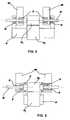
- the desired longitudinal arrangement of plates P is then achieved by keeping plates P pushed, through a pair of projecting portions 2 thereof (arranged on both sides of each plate P), against corresponding fixed abutments 3 integral with the supports L of plates P.
- the thrust against projection portions 2, in the direction of arrows 4s, is imparted directly by pairs of hydraulic cylinders 4, preferably with parallel axis to said guides and mutually balanced as regards pressure, themselves fixed to supports L.
- the end position of abutments 3 is adjusted, after which the actuation of cylinders 4 allows to bring plates P exactly into the desired position with the entry edge adjacent to the surface of drums R, in which position the plates are maintained securely in position due to the action of cylinders 4.
- the pressure of hydraulic cylinders 4 is initially adjusted to values such that the thrust globally imparted by these is in any case greater than the maximum longitudinal force Tp which the tow can determine on each of plates P; thereby, the longitudinal position of plates P remains unchanged during the operation of the crimping machine, while the degree of longitudinal freedom acquired by the plates allows an easy and reliable measurement of the above-said longitudinal force and, especially, of the variations thereof over time, individually for each of plates Pt and Pb and, separately, for each of the two sides of said plates.
- upper plate Pt is directly hinged, through bearings D, on the same shaft B of upper drum Rt through a yoke structure U.
- this solution implies two very negative aspects: on one side, the inevitable plays of the bearings E of upper drum Rt - subject to heavy wear, given the high rotation speed - generate alignment errors which transmit, amplified, to upper plate Pt; on the other side, such solution is characterised by a bulky structure, considering the large transversal extension which yoke U must have, a structure which therefore cannot have the rigidity sufficient to maintain a constant and perfect alignment during the operation of the crimping machine.
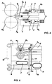
- the architecture of the crimping machine according to the present invention ( fig. 5 ) provides instead that upper plate Pt be hinged, through bearings 5, to suitable support bushes 6 of the bearings E of drum Rt.
- Bushes 6 are rigidly connected to frame W, whereon drum Rt is pivoted, and hence any alignment error on yoke U is completely removed, which is generated by any plays existing or arising during use on the bearings E of such drum.
- the indications supplied by the load cells concerning the longitudinal force Tp imparted to plates P of the crimping chamber are actually representative of the effort imparted by the filaments being crimped to the inner walls of said plates and hence represent a clear, direct and immediate indication of the state of the process under way.
- the apparatus of the invention it becomes immediately and easily possible to pre-empt the situations of possible jamming of the crimping machine, promptly reducing the closure force F of the crimping chamber C whenever an increase of longitudinal force Tp is detected; this determines a greater opening of the crimping chamber and hence a quick solution to the processing abnormality without reaching jamming of the machine.
- This allows to dramatically reduce machine standstill times and the relevant remarkable costs, both in terms of missed production and of waste of the material produced during the plant stopping and restarting steps.
- the first object of the invention is hence thereby fully achieved.
- each plate P of crimping chamber C is provided with a load cell on both sides thereof. This allows to detect not only the absolute value of longitudinal force Tp, but also the differential value thereof between the right and left side of the machine, hence allowing to provide a prompt warning of any abnormalities in the supply modes of incoming tow T, due to misalignments or other possible malfunctioning of the machines upstream of the crimping machine.
- the structure of conventional crimping machines precisely due to the large bulk of pneumatic thrust cylinders Q, provides that the closure force of crimping chamber C be applied in correspondence of the outlet edge of plates P, with the result that the constraint reaction Rv charging onto axis B of drums R has an opposite versus to the tightening force Rs of the same.
- This hence implies an overall reduction of the tightening force between drums R when the transversal thrust Ts imparted by the filaments of tow T to movable plate Pt increases beyond the project values, with the resulting drop of the longitudinal thrust on tow T due to the reduced friction imparted by the drums to the same.
- This determines a variation of the crimping rates performed on the filaments and represents an invitation to jamming.
- the application point of closure force F of plates P has instead been moved to a position comprised between the resultant Ts(r) of the transversal thrust Ts imparted by the filaments being crimped and the pivoting axis B of yoke U.
- the constraint reaction Rv determined on axis B by force F is oriented in the same direction as the tightening force Rs determined by force G, for the benefit of the process, especially when the values of the thrust Ts imparted by tow T are higher than normal (for example before a possible jamming), since in the presence of an increase of the transversal force imparted by tow T an increase of the constraint reaction Rv and hence ultimately an increase of the overall tightening force Rs+Rv is determined.
- Actuators 7 and 8 are arranged between the frame W of the crimping machine and respective support planes 9 and 10 whereon they rest with the bottom side thereof.
- Support planes 9 and 10 are hinged on a side thereof to the same frame W and are hence connected to the respective elements of application of the force - i.e. support S of upper drum Rt and yoke U which controls upper plate Pt - through pairs of connecting rods 11, 12 (only one of which is naturally visible in the lateral view of fig. 6 ) hinged to such elements and to the support planes in a suitable position for allowing the inversion of the above-described constraint reaction Rv.
- connecting rods 11 are arranged in a similar position to the pistons of the usual actuators
- connecting rods 12 may be arranged in a much more backward position than the conventional one of the free end of movable plate Pt, and precisely beyond the point of application of the resultant Ts(r) of transversal forces Ts imparted by tow T to the walls of crimping chamber C.
- the crimping machine of the invention is hence capable of fully achieving also the second proposed object.
- the third object of the present invention is finally to change the lateral constraint system of the individual filaments which make up tow T, so as to considerably increase the duration of the sacrificial elements of such system, i.e. of the constraint plates.
- the control circuit of plates Z is arranged so as to maintain said plates in a "constant position", regardless of the pressure which is applied to the same by tow T being processed.
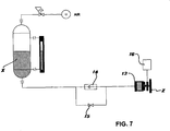
- a pneumo-hydraulic circuit comprising a tank X partly filled with fluid and kept at constant pressure by compressed air (AIR) introduced into the upper part thereof.
- a cylinder 13 controls the thrust onto plate Z and is supplied with the fluid of tank X through a one-way valve 14 which allows to exclude any backflow of working fluid from cylinder 13 to tank X, when a respective by-pass valve 15 is closed.
- An electric motor 16 controls, in a way known per se, the rotation of plate Z to even out the wear thereof.
- plates Z are pushed against drums R at a much lower pressure than the one conventionally used to oppose the thrust of tow T in the heaviest working conditions, preferably below 50% of said pressure and even more preferably even up to about 25% of such pressure, suitably adjusting the pressure of the compressed air fed to the upper part of tank X, after which by-pass valve 15 is closed.
- a thrust increase by tow T occurs, such as to overcome the thrust imparted by plates Z
- one-way valve 14 closes and does not allow backflow of the fluid from cylinder 13 to tank X, hence forcing this circuit part to work with a closed volume of fluid. Assuming this volume of liquid as incompressible, the pressure inside the final part of the circuit will automatically rise to the extent necessary to oppose the pressure increase generated by tow T and the backward movement of plates Z, due to such pressure increase, will hence be fully negligible.
- plates Z are kept in a fixed position in contact with the lateral surface of drums R, with the minimum necessary force, exploiting the incompressibility of the fluid to resist the thrust peaks which may occur during processing.
- the hydraulic circuit used for controlling plates Z illustrated in fig. 7 is a mixed pneumo-hydraulic circuit - whose arrangement is well-known per se and hence is not described here in further detail - nothing prevents the use of fully hydraulic circuits.
- This method for controlling the position of the plates brings remarkable advantages. Firstly, the useful life of the plates is remarkably increased, up until covering an entire production shift, thereby fulfilling also the third object of the invention. Moreover, the thermal and mechanical stresses resulting from the chafing between plates Z and drums Rt and Rb are remarkably diminished, so as to significantly reduce the wear of the drum edges and to make the cooling operations of the same easier.
Landscapes
- Engineering & Computer Science (AREA)
- Mechanical Engineering (AREA)
- Textile Engineering (AREA)
- Yarns And Mechanical Finishing Of Yarns Or Ropes (AREA)
Claims (19)
- Appareil destiné à friser une pluralité de filaments continus de fibres chimiques, reliés entre eux en un câble étendu, d'une section sensiblement rectangulaire, du type qui comprend une paire de tambours (Rt, Rb) entraînés par moteur permettant d'alimenter le câble dans une chambre confinée (C) dans laquelle la frisure est réalisée, agencée immédiatement en aval desdits tambours (Rt, Rb) et consistant en une paire de plaques opposées (Pt, Pb), l'un desdits tambours (Rb) étant monté sur le cadre de l'appareil dans une position fixe, libre en rotation autour de son axe, alors que l'autre tambour (Rt) est lui-même monté libre en rotation sur un support mobile (S) articulé (en A) au cadre (W) dudit appareil, l'une desdites plaques (Pb) étant montée sur le cadre de l'appareil dans une position fixe, alors que l'autre plaque (Pt) est articulée au même axe de rotation (B) du tambour correspondant (Rt), une force de serrage (Rs) étant appliquée au tambour mobile ((Rt), en vue de transmettre une pression d'étirage au câble, et une force de fermeture étant transmise à ladite plaque mobile (Pt), en vue de communiquer une pression à la chambre (C) de formation de frisures, caractérisé en ce qu'au moins l'une desdites plaques (Pt, Pb) est montée sur un support respectif (L) à travers deux guides linéaires ou plus, munis d'un système double rouleau ou à recirculation par billes, parallèles à la direction de progression du câble (T), et sa position longitudinale est déterminée par une paire de cylindres hydrauliques (4) qui, en l'absence d'autres systèmes de verrouillage mécanique ou oléodynamique, maintiennent ladite plaque, ou une partie de celle-ci, poussée contre des butées fixes (3) respectives, lesdits cylindres hydrauliques (4) et lesdites butées fixes (3) étant fixés audit support de plaque (L), et en ce qu'un ou plusieurs moyens de détection de force sont agencés entre ledit support (L) et ladite plaque (Pt), en vue de détecter les
changements au niveau du couple de serrage pendant le fonctionnement de l'appareil, lesdits changements représentant la force longitudinale variable (Tp) transmise par les filaments du câble (T) en cours de traitement sur ladite plaque (Pt). - Appareil à friser tel que revendiqué dans la revendication 1, dans lequel ledit moyen de détection de force est agencé entre chacune desdites butées fixes (3) et une partie en projection (2) correspondante de ladite plaque (Pt).
- Appareil à friser tel que revendiqué dans la revendication 1 ou 2, dans lequel ledit moyen de détection de force est une cellule de charge.
- Appareil à friser tel que revendiqué dans la revendication 3, dans lequel ladite cellule de charge est réglée à zéro à la pression de fermeture nominale desdits cylindres hydrauliques (4).
- Appareil à friser tel que revendiqué dans la revendication 1, dans lequel ledit moyen de détection de force de charge est un transducteur de pression capable de détecter la pression dans lesdits cylindres hydrauliques (4), lorsque le circuit d'alimentation associé est fermé.
- Appareil à friser tel que revendiqué dans la revendication 1, dans lequel lesdits cylindres ont un axe parallèle auxdits guides linéaires.
- Appareil à friser tel que revendiqué dans la revendication 1, dans lequel la pression interne desdits cylindres (4) est équilibrée.
- Appareil à friser tel que revendiqué dans la revendication 1, dans lequel la fourche (U) soutenant la plaque mobile (Pt) pivote sur des paliers (5) reçus dans des bagues de paliers (6), solidaires du cadre de l'appareil (W) et coaxiales à l'arbre (B) du tambour mobile (Rt).
- Appareil à friser tel que revendiqué dans la revendication 8, dans lequel lesdites bagues de paliers (6)
accueillent également les paliers (E) soutenant ledit tambour mobile (rt). - Appareil à friser tel que revendiqué dans les revendications 8 et 9, dans lequel les paliers (5) soutenant la plaque mobile (Pt) sont agencés à l'intérieur des paliers (E) soutenant le tambour mobile (Rt).
- Appareil à friser tel que revendiqué dans la revendication 1, caractérisé en ce que ladite force de fermeture de la plaque mobile (Pt) est appliquée dans une position comprise entre le point d'application de la résultante (Ts(r)) de la force transversale (Ts) transmise par les filaments du câble (T) contre la plaque mobile (Pt) et l'axe de pivotement (B) de ladite plaque.
- Appareil à friser tel que revendiqué dans la revendication 11, dans lequel ladite force de fermeture de la plaque mobile (Pt) est appliquée par un ressort pneumatique (8), agencé entre le cadre (W) de l'appareil et un plan de support (10) articulé de manière correspondante à l'un de ses côtés audit cadre (W) et relié par sa partie oscillante à la fourche (U) soutenant ladite plaque mobile (Pt) par une paire de tiges de raccordement (12).
- Appareil à friser tel que revendiqué dans la revendication 12, dans lequel ladite force de serrage du tambour mobile (Rt) est transmise par un ressort amortisseur pneumatique (7), agencé entre le cadre (W) de l'appareil et un plan de support (9) articulé de manière correspondante à l'un de ses côtés audit cadre (W) et relié par sa partie oscillante au support (S) dudit tambour (Rt) par une paire de tiges de raccordement (11).
- Appareil à friser tel que revendiqué dans la revendication 11, comprenant en outre de petites plaques (Z) contraignant les filaments du câble (T), lesdites plaques étant agencées de manière correspondante avec la zone de contact entre lesdits tambours (Rt, Rb) et en contact avec la surface latérale de ces derniers, caractérisé en ce que la position de chacune desdites plaques dans la direction parallèle aux axes desdits tambours et vers l'intérieur de ces derniers est régulée par la poussée d'un cylindre hydraulique (13) respectif recevant une pression inférieure à la pression nécessaire pour contraindre le câble (T) entre lesdits tambours (Rt, Rb) dans les conditions de fonctionnement les plus lourdes, et en ce qu'au moins la partie d'extrémité du circuit d'alimentation de liquide audit cylindre (13) est à volume fermé pendant le fonctionnement de l'appareil.
- Appareil à friser tel que revendiqué dans la revendication 14, dans lequel la condition de volume fermé du circuit alimentant du liquide audit cylindre hydraulique (13) est réalisée par le biais d'une valve à une voie (14) agencée en amont dudit cylindre (13).
- Appareil à friser tel que revendiqué dans la revendication 14, dans lequel la pression d'alimentation dudit cylindre hydraulique (13) est en-dessous de 50% de la pression nécessaire pour contraindre les filaments du câble (T) entre lesdits tambours (Rt, Rb) dans les conditions de fonctionnement les plus lourdes, et de préférence égale à 25% de ladite pression.
- Procédé de commande de la frisure d'une pluralité de filaments continus de fibres chimiques, reliés en un câble étendu à section sensiblement rectangulaire, dans un appareil tel que revendiqué dans l'une quelconque des revendications 1 à 16, dans lequel la détection continue de la valeur de la force longitudinale (Tp) transmise par le câble (T) contre la paroi interne d'au moins l'une des plaques (Pt, Pb) définissant la chambre à friser (C) est utilisée pour surveiller en continu la qualité de la frisure obtenue.
- Procédé de commande de la frisure de filaments en fibres chimiques tel que revendiqué dans la revendication 17, dans lequel la force de fermeture (F) de la plaque mobile (Pt) de la chambre à friser (C) est ajustée selon la valeur détectée instantanée de la force longitudinale (Tp) transmise par les filaments du câble (T) à la paroi interne d'au moins l'une des plaques (Pt, Pb) qui définissent la chambre à friser (C).
- Procédé de commande de la frisure du filament en fibres chimiques tel que revendiqué dans la revendication 17, dans lequel le différentiel de la force longitudinale (Tp) transmise par le câble (T) contre la paroi interne d'au moins l'une des plaques (Pt, Pb) définissant la chambre à friser (C), tel qu'on le détecte entre le côté droit et le côté gauche de ladite plaque, est utilisé comme indicateur d'un dysfonctionnement des dispositifs de formation de câble disposés en amont dudit appareil.
Priority Applications (4)
| Application Number | Priority Date | Filing Date | Title |
|---|---|---|---|
| DE602008005706T DE602008005706D1 (de) | 2008-03-03 | 2008-03-03 | Vorrichtung zum Kräuseln von Chemiefaserfäden und Steuerverfahren |
| EP08425131A EP2098622B1 (fr) | 2008-03-03 | 2008-03-03 | Dispositif pour friser des filaments de fibres synthétiques et méthodes de contrôle |
| US12/395,832 US7748092B2 (en) | 2008-03-03 | 2009-03-02 | Apparatus for crimping chemical-fibre filaments and control methods thereof |
| CN200910203922.1A CN101565868B (zh) | 2008-03-03 | 2009-03-03 | 卷曲化纤长丝的装置及其控制方法 |
Applications Claiming Priority (1)
| Application Number | Priority Date | Filing Date | Title |
|---|---|---|---|
| EP08425131A EP2098622B1 (fr) | 2008-03-03 | 2008-03-03 | Dispositif pour friser des filaments de fibres synthétiques et méthodes de contrôle |
Publications (2)
| Publication Number | Publication Date |
|---|---|
| EP2098622A1 EP2098622A1 (fr) | 2009-09-09 |
| EP2098622B1 true EP2098622B1 (fr) | 2011-03-23 |
Family
ID=39691318
Family Applications (1)
| Application Number | Title | Priority Date | Filing Date |
|---|---|---|---|
| EP08425131A Ceased EP2098622B1 (fr) | 2008-03-03 | 2008-03-03 | Dispositif pour friser des filaments de fibres synthétiques et méthodes de contrôle |
Country Status (4)
| Country | Link |
|---|---|
| US (1) | US7748092B2 (fr) |
| EP (1) | EP2098622B1 (fr) |
| CN (1) | CN101565868B (fr) |
| DE (1) | DE602008005706D1 (fr) |
Families Citing this family (7)
| Publication number | Priority date | Publication date | Assignee | Title |
|---|---|---|---|---|
| CN102828294B (zh) * | 2011-06-16 | 2015-04-15 | 南通醋酸纤维有限公司 | 填塞箱卷曲机耐磨夹板装置 |
| KR101254251B1 (ko) * | 2012-11-05 | 2013-04-12 | 조성욱 | 섬유 주름 가공용 권축장치 |
| WO2014122741A1 (fr) * | 2013-02-06 | 2014-08-14 | 富山フィルタートウ株式会社 | Dispositif de crêpage d'étoupe et procédé de fabrication d'une étoupe crêpée |
| CN103409831A (zh) * | 2013-07-30 | 2013-11-27 | 苏州豪建纺织有限公司 | 一种起绒熔丝结构 |
| ITUB20155106A1 (it) * | 2015-11-02 | 2017-05-02 | M A E S P A | Macchina crettatrice per il trattamento di fibre chimiche |
| US12686956B2 (en) * | 2018-12-04 | 2026-07-21 | Oerlikon Textile Gmbh & Co. Kg | Method for operating a crimping apparatus, and crimping apparatus |
| NL2023878B1 (en) * | 2019-09-23 | 2021-05-25 | Ultimaker Bv | A filament path length measuring device |
Family Cites Families (23)
| Publication number | Priority date | Publication date | Assignee | Title |
|---|---|---|---|---|
| NL78597C (fr) * | 1953-05-28 | |||
| US2856640A (en) * | 1954-02-01 | 1958-10-21 | Deering Milliken Res Corp | Apparatus for crimping textile strands |
| US2734252A (en) * | 1954-10-08 | 1956-02-14 | Crimping apparatus | |
| US2740992A (en) * | 1955-03-01 | 1956-04-10 | Bancroft & Sons Co J | Crimping and winding apparatus |
| US2862279A (en) * | 1956-04-10 | 1958-12-02 | Allied Chem | Tow crimping apparatus |
| US3353223A (en) * | 1963-08-19 | 1967-11-21 | Eastman Kodak Co | Method and apparatus for crimping |
| US3248770A (en) * | 1964-01-23 | 1966-05-03 | Bancroft & Sons Co J | Crimping apparatus |
| NL6711372A (fr) * | 1967-08-18 | 1969-02-20 | ||
| GB1237218A (en) | 1967-11-20 | 1971-06-30 | Ici Ltd | Improved polyester fibres and tows |
| DE1816028C3 (de) | 1968-12-20 | 1982-06-09 | Vepa AG, 4125 Riehen, Basel | Vorrichtung zum Kräuseln von synthetischen Fadenscharen |
| GB1268883A (en) * | 1969-07-30 | 1972-03-29 | Bancroft & Sons Co J | Improved stuffer crimper |
| CH529856A (de) | 1970-08-10 | 1972-10-31 | Vepa Ag | Vorrichtung zum Kräuseln synthetischer Fadenscharen |
| US3938226A (en) * | 1974-03-13 | 1976-02-17 | Kling-Tecs, Inc. | Apparatus for crimping yarn |
| US4041584A (en) * | 1976-09-29 | 1977-08-16 | E. I. Du Pont De Nemours And Company | Loading apparatus for crimper rolls |
| DE2733455C2 (de) | 1977-07-25 | 1982-12-30 | Barmag Barmer Maschinenfabrik Ag, 5630 Remscheid | Stauchkammer zur Texturierung von Chemiefaser |
| DE3626522A1 (de) * | 1986-06-26 | 1988-02-11 | Vepa Ag | Stauchkammerkraeuselvorrichtung zum kraeuseln synthetischer fadenscharen |
| DE3631905A1 (de) | 1986-09-19 | 1988-03-31 | Bayer Ag | Stauchkammerkraeusel und verfahren zur herstellung von gekraeuselten synthetischen fasern |
| US5025538A (en) | 1990-03-30 | 1991-06-25 | Hoechst Celanese Corporation | Apparatus for crimping tow including stuffer box, crimping rollers and molding rollers |
| US5485662A (en) | 1994-04-29 | 1996-01-23 | Hercules Incorporated | Apparatus and method for crimping fiber for nonwoven applications |
| DE19537958C1 (de) | 1995-10-12 | 1996-11-14 | Neumag Gmbh | Vorrichtung zum Kräuseln von synthetischen Fadenbündeln oder -bändern |
| DE19538423C2 (de) * | 1995-10-16 | 1997-08-21 | Neumag Gmbh | Vorrichtung zum Kräuseln von synthetischen Fadenbündeln oder -bändern |
| DE59908662D1 (de) * | 1998-09-10 | 2004-04-01 | Barmag Barmer Maschf | Texturiermaschine zum texturieren und aufwickeln eines fadens |
| JP4157474B2 (ja) * | 2001-09-01 | 2008-10-01 | ザウラー ゲゼルシャフト ミット ベシュレンクテル ハフツング ウント コンパニー コマンディートゲゼルシャフト | テクスチャード加工機 |
-
2008
- 2008-03-03 EP EP08425131A patent/EP2098622B1/fr not_active Ceased
- 2008-03-03 DE DE602008005706T patent/DE602008005706D1/de active Active
-
2009
- 2009-03-02 US US12/395,832 patent/US7748092B2/en active Active
- 2009-03-03 CN CN200910203922.1A patent/CN101565868B/zh active Active
Also Published As
| Publication number | Publication date |
|---|---|
| CN101565868A (zh) | 2009-10-28 |
| DE602008005706D1 (de) | 2011-05-05 |
| US7748092B2 (en) | 2010-07-06 |
| CN101565868B (zh) | 2013-05-15 |
| EP2098622A1 (fr) | 2009-09-09 |
| US20090230583A1 (en) | 2009-09-17 |
Similar Documents
| Publication | Publication Date | Title |
|---|---|---|
| US7748092B2 (en) | Apparatus for crimping chemical-fibre filaments and control methods thereof | |
| US5928579A (en) | Apparatus and method for spinning and winding multifilament yarns | |
| US8893359B2 (en) | Yarn sluice for sealing a pressurized yarn treating chamber | |
| CN113638068A (zh) | 一种产业用生物基聚酰胺纺丝牵伸卷绕联合机 | |
| JP5543145B2 (ja) | 撚線形態の繊維材料を引き伸ばす練篠機構を有する紡績用前処理機のためのまたは該前処理機における装置 | |
| EP2573231B1 (fr) | Fileuse | |
| CN107208316B (zh) | 用于拉伸大量熔纺的纤维条子的方法和设备 | |
| CN1370861A (zh) | 一种在线检测技术 | |
| JP6267580B2 (ja) | 糸巻取装置及びマーキング形成方法 | |
| CN107460566B (zh) | 形式为并条机的纺纱准备机器及其运行方法 | |
| JP5965115B2 (ja) | 繊維機械のドラフトシステムおよびその運転方法 | |
| CN106149121B (zh) | 给油导引器和纺纱牵引装置 | |
| US7739774B2 (en) | Apparatus on a spinning preparation machine, for example, a draw frame, flat card, combing machine or the like, having at least two driven drafting systems | |
| CN105764823A (zh) | 变形机和用于操作变形机的卷绕站的方法 | |
| CN111809259B (zh) | 短纤维成品后道生产线 | |
| CN101506425B (zh) | 对运行纱线进行热处理的方法以及执行该方法的捻线机 | |
| CN117342350A (zh) | 一种纱线张力系统控制装置 | |
| CN101634065A (zh) | 假捻变形机 | |
| EP3168340B1 (fr) | Dispositif de filage à jet d'air et machine à filer | |
| CN102971455B (zh) | 用于纺纱机的牵伸装置 | |
| CN217920799U (zh) | 一种非组织布生产线防缠装置 | |
| NL1021659C1 (nl) | Werkwijze en inrichting voor het snijden van vezels en sturen van het proces en/of voorgaande processtappen. | |
| CN114229609A (zh) | 一种干区张力平衡装置 | |
| CN101248227A (zh) | 棉束供给系统 | |
| CN113795617A (zh) | 具有用于精梳机的分离滚筒对的压力滚筒的装置的分离滚筒单元 |
Legal Events
| Date | Code | Title | Description |
|---|---|---|---|
| PUAI | Public reference made under article 153(3) epc to a published international application that has entered the european phase |
Free format text: ORIGINAL CODE: 0009012 |
|
| AK | Designated contracting states |
Kind code of ref document: A1 Designated state(s): AT BE BG CH CY CZ DE DK EE ES FI FR GB GR HR HU IE IS IT LI LT LU LV MC MT NL NO PL PT RO SE SI SK TR |
|
| AX | Request for extension of the european patent |
Extension state: AL BA MK RS |
|
| 17P | Request for examination filed |
Effective date: 20091209 |
|
| AKX | Designation fees paid |
Designated state(s): DE IT TR |
|
| GRAC | Information related to communication of intention to grant a patent modified |
Free format text: ORIGINAL CODE: EPIDOSCIGR1 |
|
| GRAP | Despatch of communication of intention to grant a patent |
Free format text: ORIGINAL CODE: EPIDOSNIGR1 |
|
| GRAS | Grant fee paid |
Free format text: ORIGINAL CODE: EPIDOSNIGR3 |
|
| GRAA | (expected) grant |
Free format text: ORIGINAL CODE: 0009210 |
|
| AK | Designated contracting states |
Kind code of ref document: B1 Designated state(s): DE IT TR |
|
| REF | Corresponds to: |
Ref document number: 602008005706 Country of ref document: DE Date of ref document: 20110505 Kind code of ref document: P |
|
| REG | Reference to a national code |
Ref country code: DE Ref legal event code: R096 Ref document number: 602008005706 Country of ref document: DE Effective date: 20110505 |
|
| PLBE | No opposition filed within time limit |
Free format text: ORIGINAL CODE: 0009261 |
|
| STAA | Information on the status of an ep patent application or granted ep patent |
Free format text: STATUS: NO OPPOSITION FILED WITHIN TIME LIMIT |
|
| 26N | No opposition filed |
Effective date: 20111227 |
|
| REG | Reference to a national code |
Ref country code: DE Ref legal event code: R097 Ref document number: 602008005706 Country of ref document: DE Effective date: 20111227 |
|
| PGFP | Annual fee paid to national office [announced via postgrant information from national office to epo] |
Ref country code: TR Payment date: 20170302 Year of fee payment: 10 Ref country code: IT Payment date: 20170308 Year of fee payment: 10 |
|
| PG25 | Lapsed in a contracting state [announced via postgrant information from national office to epo] |
Ref country code: IT Free format text: LAPSE BECAUSE OF NON-PAYMENT OF DUE FEES Effective date: 20180303 |
|
| PGFP | Annual fee paid to national office [announced via postgrant information from national office to epo] |
Ref country code: DE Payment date: 20200303 Year of fee payment: 13 |
|
| REG | Reference to a national code |
Ref country code: DE Ref legal event code: R119 Ref document number: 602008005706 Country of ref document: DE |
|
| PG25 | Lapsed in a contracting state [announced via postgrant information from national office to epo] |
Ref country code: DE Free format text: LAPSE BECAUSE OF NON-PAYMENT OF DUE FEES Effective date: 20211001 |
|
| PG25 | Lapsed in a contracting state [announced via postgrant information from national office to epo] |
Ref country code: TR Free format text: LAPSE BECAUSE OF NON-PAYMENT OF DUE FEES Effective date: 20180303 |