EP2098768B1 - Dispositif de verrouillage pour verrouiller les colliers de serrage de tube - Google Patents
Dispositif de verrouillage pour verrouiller les colliers de serrage de tube Download PDFInfo
- Publication number
- EP2098768B1 EP2098768B1 EP20090003145 EP09003145A EP2098768B1 EP 2098768 B1 EP2098768 B1 EP 2098768B1 EP 20090003145 EP20090003145 EP 20090003145 EP 09003145 A EP09003145 A EP 09003145A EP 2098768 B1 EP2098768 B1 EP 2098768B1
- Authority
- EP
- European Patent Office
- Prior art keywords
- collar
- locking
- locking device
- end portion
- plate length
- Prior art date
- Legal status (The legal status is an assumption and is not a legal conclusion. Google has not performed a legal analysis and makes no representation as to the accuracy of the status listed.)
- Not-in-force
Links
Images


Classifications
-
- F—MECHANICAL ENGINEERING; LIGHTING; HEATING; WEAPONS; BLASTING
- F16—ENGINEERING ELEMENTS AND UNITS; GENERAL MEASURES FOR PRODUCING AND MAINTAINING EFFECTIVE FUNCTIONING OF MACHINES OR INSTALLATIONS; THERMAL INSULATION IN GENERAL
- F16L—PIPES; JOINTS OR FITTINGS FOR PIPES; SUPPORTS FOR PIPES, CABLES OR PROTECTIVE TUBING; MEANS FOR THERMAL INSULATION IN GENERAL
- F16L3/00—Supports for pipes, cables or protective tubing, e.g. hangers, holders, clamps, cleats, clips, brackets
- F16L3/08—Supports for pipes, cables or protective tubing, e.g. hangers, holders, clamps, cleats, clips, brackets substantially surrounding the pipe, cable or protective tubing
- F16L3/12—Supports for pipes, cables or protective tubing, e.g. hangers, holders, clamps, cleats, clips, brackets substantially surrounding the pipe, cable or protective tubing comprising a member substantially surrounding the pipe, cable or protective tubing
-
- F—MECHANICAL ENGINEERING; LIGHTING; HEATING; WEAPONS; BLASTING
- F16—ENGINEERING ELEMENTS AND UNITS; GENERAL MEASURES FOR PRODUCING AND MAINTAINING EFFECTIVE FUNCTIONING OF MACHINES OR INSTALLATIONS; THERMAL INSULATION IN GENERAL
- F16L—PIPES; JOINTS OR FITTINGS FOR PIPES; SUPPORTS FOR PIPES, CABLES OR PROTECTIVE TUBING; MEANS FOR THERMAL INSULATION IN GENERAL
- F16L3/00—Supports for pipes, cables or protective tubing, e.g. hangers, holders, clamps, cleats, clips, brackets
- F16L3/08—Supports for pipes, cables or protective tubing, e.g. hangers, holders, clamps, cleats, clips, brackets substantially surrounding the pipe, cable or protective tubing
- F16L3/10—Supports for pipes, cables or protective tubing, e.g. hangers, holders, clamps, cleats, clips, brackets substantially surrounding the pipe, cable or protective tubing divided, i.e. with two members engaging the pipe, cable or protective tubing
- F16L3/1008—Supports for pipes, cables or protective tubing, e.g. hangers, holders, clamps, cleats, clips, brackets substantially surrounding the pipe, cable or protective tubing divided, i.e. with two members engaging the pipe, cable or protective tubing with two members engaging the pipe, cable or tubing, both being made of thin band material completely surrounding the pipe
-
- F—MECHANICAL ENGINEERING; LIGHTING; HEATING; WEAPONS; BLASTING
- F16—ENGINEERING ELEMENTS AND UNITS; GENERAL MEASURES FOR PRODUCING AND MAINTAINING EFFECTIVE FUNCTIONING OF MACHINES OR INSTALLATIONS; THERMAL INSULATION IN GENERAL
- F16L—PIPES; JOINTS OR FITTINGS FOR PIPES; SUPPORTS FOR PIPES, CABLES OR PROTECTIVE TUBING; MEANS FOR THERMAL INSULATION IN GENERAL
- F16L3/00—Supports for pipes, cables or protective tubing, e.g. hangers, holders, clamps, cleats, clips, brackets
- F16L3/08—Supports for pipes, cables or protective tubing, e.g. hangers, holders, clamps, cleats, clips, brackets substantially surrounding the pipe, cable or protective tubing
- F16L3/10—Supports for pipes, cables or protective tubing, e.g. hangers, holders, clamps, cleats, clips, brackets substantially surrounding the pipe, cable or protective tubing divided, i.e. with two members engaging the pipe, cable or protective tubing
- F16L3/1075—Supports for pipes, cables or protective tubing, e.g. hangers, holders, clamps, cleats, clips, brackets substantially surrounding the pipe, cable or protective tubing divided, i.e. with two members engaging the pipe, cable or protective tubing with two members, the two members being joined with a hinge on one side and fastened together on the other side
-
- F—MECHANICAL ENGINEERING; LIGHTING; HEATING; WEAPONS; BLASTING
- F16—ENGINEERING ELEMENTS AND UNITS; GENERAL MEASURES FOR PRODUCING AND MAINTAINING EFFECTIVE FUNCTIONING OF MACHINES OR INSTALLATIONS; THERMAL INSULATION IN GENERAL
- F16L—PIPES; JOINTS OR FITTINGS FOR PIPES; SUPPORTS FOR PIPES, CABLES OR PROTECTIVE TUBING; MEANS FOR THERMAL INSULATION IN GENERAL
- F16L55/00—Devices or appurtenances for use in, or in connection with, pipes or pipe systems
- F16L55/02—Energy absorbers; Noise absorbers
- F16L55/033—Noise absorbers
- F16L55/035—Noise absorbers in the form of specially adapted hangers or supports
Definitions
- the present invention relates to a locking device, which has been particularly designed for locking tube clamping collars or clamping bands. Examples of such locking devices can be found in FR 2631678 or DE 19842171 .
- outlet tubes or pipes usually used in buildings and the like are generally made of a plastics material and are supported by supporting collars or clamps which are fixed to the building walls by fixing brackets.
- Said outlet tubes are subjected to expanding or dilating movements due to the climatic conditions and different temperatures to the waste waters.
- the aim of the present invention is to provide such a locking device, specifically designed for locking tube collars or clamps, adapted to solve the above disclosed problems.
- a main object of the invention is to provide such a locking device allowing the supporting elements to which said device is affixed to be easily and quickly adjusted, so as to operate as an adjustable reversible spacer elements for flange, collar or clamp elements used as pipe or tube supporting elements.
- Another object of the present invention is to provide such a locking device allowing the collar to be quickly and easily installed.
- Yet another object of the present invention is to provide such a locking device which can be applied to several types of collars or clamps, both for fixing outlet tubes, and for other applications.
- Yet another object of the present invention is to provide such a locking device which has reversible properties, that is is adapted to allow a quick and easy disassembling of the tube collar or clamp.
- Yet another object of the present invention is to provide such a locking device, which, owing to specifically designed constructional features, is very reliable and safe in operation.
- Yet another object of the present invention is to provide such a locking device which can be easily made starting from easily available elements and materials and which, moreover, is very competitive from a mere economic standpoint.
- a locking device for locking tube clamping collars or bands characterized in that said locking device comprises a locking-screw element adapted to be applied to a first free end portion of a clamping collar or the like, at two different positions, one for an enlarged applying diameter and the other for a reduced applying diameter, said locking-screw element being adapted to swing on the first free end portion thereby it can be latched to the second free end portion of said collar, to lock said collar on a tube.
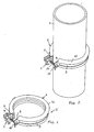
- the locking device according to the present invention which has been generally indicated by the reference number 1, is designed for application to a supporting element 2, such as a supporting collar, to be used for clamping a tube, generally indicated by the reference number 3.
- the collar 2 is herein constituted by two semicircular collar portions, that is a first collar portion 4 and a second collar portion 5.
- Both said collar portions 4 and 5 have an end part thereof adapted to engage with the end portion of the other respective part to form a hinge 6.
- the first portion 4 of the collar comprises a contoured or shaped end 7, including a throughgoing hole 8.
- the contoured or shaped end 7 of the half-collar 4 has a curved contour and includes a middle slots designed for receiving the locking device 1 in its two use positions, while preventing said locking device 1 from turning.
- the second portion 5 of the collar comprises, in turn, a contoured end portion 9 including a radially extending slot 10 which is opened at the outer edge of said contoured or shaped end 9.
- the collar 2 comprises moreover a rubber sheath 11, arranged, in a use condition, between the outer surface of the tube 3 and the inner surface of the collar.
- the locking device 1 is constituted by a metal plate element, having a S-shape.
- said metal plate is so constructed as to define a first plate length 12, including a throughgoing hole 15, a second plate length 13 including a threaded hole 16 and a third plate length 14 including a respective threaded hole 17.
- the first plate length 12 is coupled to the second plate length 13 by a broad fitting loop portion 18.
- the second plate length 13 is coupled to the third plate length 14 by a reduced width fitting loop portion 19.
- the threaded portions or lengths 13 and 14 will be arranged in a close relationship with one another, whereas the first plate length 12, including the above mentioned throughgoing hole, is spaced from the seconde plate threaded length 13.
- the device 1 is applied to the contoured end portions 7 and 9 of the collar by a locking screw 20, which, as clamped or screwed-on, will allow the collar to be firmly fixed to the tube or pipe.
- the locking device 1 can be applied to the collar at two use positions, that is an enlarged diameter position and a reduced diameter position.
- the locking device will be applied by encompassing by its two threaded lengths 13 and 14 the contoured end portion 7 of the collar, thereby leaving on outside the first length 12 with its throughgoing hole, as is shown in figures 4 , 6 , 8 and 10 .
- the locking device will be applied by encompassing with its two threaded lengths 13 and 14 the contoured end portion 7 of the collar so as to leave the first length 12 and respective throughgoing hole downward directed, that is between the two contoured end portions 7 and 9 of the collar, as is shown in figures 3 , 5 , 7 and 9 .
- the width of the throughgoing hole 8 of the contoured end portion 7 will allow the locking device - locking screw assembly to awing, as shown in figures 5 and 6 .
- the slot 10 is so designed as to allow the stem of the screw 20 to pass therethrough, but having a width narrower than that of the head of the screw, thereby, by clamping or screwing on the screw, it will be possible to correspondingly clamp the portions 4 and 5 on the pipe or tube 3, as it is schematically shown in figures 3 to 10 in sequence.
- the invention has provided a locking device which allows the diameter of the collar or like a clamping element to be easily adjusted, with the device mounted either in a direction or in the other direction on an end portion of one of the two collar parts, while clamping the assembly by the locking screw.
- the used materials, as well as the contingent size and shapes can be any, depending on requirements.
Landscapes
- Engineering & Computer Science (AREA)
- General Engineering & Computer Science (AREA)
- Mechanical Engineering (AREA)
- Clamps And Clips (AREA)
- Supports For Pipes And Cables (AREA)
- Joints That Cut Off Fluids, And Hose Joints (AREA)
Claims (5)
- Dispositif de blocage (1) permettant de bloquer des colliers ou des bandes de serrage de tube (2), comprenant un élément de vis de blocage (20) apte à être appliqué sur une première portion d'extrémité libre (7) d'un collier de serrage (2) ou similaire, au niveau de deux positions différentes, l'une pour un diamètre d'application élargi et l'autre pour un diamètre d'application réduit, ledit élément de vis de blocage (20) étant câble de basculer sur la première portion d'extrémité libre (7) grâce à quoi il peut être enclenché sur la seconde portion d'extrémité libre (9) dudit collier, pour bloquer ledit collier (2) sur un tube (3), caractérisé en ce que ledit dispositif de blocage comprend une plaque en forme de S (1) ayant une première longueur de plaque (12) munie d'un trou traversant (15), une seconde longueur de plaque (13) munie d'un trou fileté (16) et une troisième longueur de plaque (14) munie d'un trou fileté (17), la première longueur de plaque (12) étant couplée à la seconde longueur de plaque (13) par une portion de boucle à ajustement large (18), la seconde longueur de plaque (13) étant couplée à la troisième longueur de plaque (14) par une portion de boucle à ajustement de largeur réduite (19), la plaque en forme de S (1) ayant une première position de blocage pour des diamètres agrandis avec la première longueur de plaque (12) située entre la première (7) et la seconde (9) portions d'extrémité du collier (2), et une seconde position de blocage pour des diamètres réduits, tournés vers le haut par rapport à la première position, la première longueur de plaque (12) étant située vers l'extérieur desdites première et seconde portions (7, 9).
- Dispositif de blocage selon la revendication 1, caractérisé en ce que ledit collier (2) est constitué de deux portions de collier semi-circulaires, une première (4) et une seconde (5), la première portion de collier (4) comprenant ladite première portion d'extrémité (7), la première portion d'extrémité (7) incluant un trou traversant (8), la seconde portion de collier (5) comprenant ladite seconde portion d'extrémité (9), la seconde portion d'extrémité (9) incluant une fente s'étendant radialement (10) ouverte au niveau du bord extérieur.
- Dispositif de blocage selon la revendication 2, caractérisé en ce que lesdites parties de collier (4, 5) ont une partie d'extrémité conçue pour s'engager sur la partie d'extrémité de l'autre partie respective afin de former une charnière (6).
- Dispositif de blocage selon la revendication 2, caractérisé en ce que ladite fente (10) de la seconde partie d'extrémité (9) du collier a une largeur conçue pour permettre à une tige de l'élément de vis de blocage (20) de le traverser mais plus étroite que celle d'une tête dudit élément de vis de blocage (20).
- Dispositif de blocage selon l'une quelconque des revendications précédentes, caractérisé en ce que ledit collier (2) comprend une gaine en caoutchouc (11) agencée, pendant l'utilisation, entre une surface externe du tube (3) et la surface interne du collier (2).
Applications Claiming Priority (1)
| Application Number | Priority Date | Filing Date | Title |
|---|---|---|---|
| ITMI20080375 ITMI20080375A1 (it) | 2008-03-06 | 2008-03-06 | Dispositivo di bloccaggio, particolarmente per collari o fascette di fissaggio di tubazioni. |
Publications (3)
| Publication Number | Publication Date |
|---|---|
| EP2098768A2 EP2098768A2 (fr) | 2009-09-09 |
| EP2098768A3 EP2098768A3 (fr) | 2010-10-06 |
| EP2098768B1 true EP2098768B1 (fr) | 2012-06-06 |
Family
ID=40292837
Family Applications (1)
| Application Number | Title | Priority Date | Filing Date |
|---|---|---|---|
| EP20090003145 Not-in-force EP2098768B1 (fr) | 2008-03-06 | 2009-03-05 | Dispositif de verrouillage pour verrouiller les colliers de serrage de tube |
Country Status (4)
| Country | Link |
|---|---|
| EP (1) | EP2098768B1 (fr) |
| ES (1) | ES2390208T3 (fr) |
| IT (1) | ITMI20080375A1 (fr) |
| PT (1) | PT2098768E (fr) |
Families Citing this family (7)
| Publication number | Priority date | Publication date | Assignee | Title |
|---|---|---|---|---|
| GB0821682D0 (en) * | 2008-11-27 | 2008-12-31 | Tappex Thread Inserts Ltd | Clips |
| IT1401564B1 (it) * | 2010-07-22 | 2013-07-26 | Ln 2 Srl Socio Unico | Dispositivo a collare per il bloccaggio anti-sfilamento di sezioni tubolari per il convogliamento di aeriformi, in particolare per il convogliamento a scarico di fumi o vapori |
| GB2528094B (en) * | 2014-07-09 | 2017-04-26 | Jaguar Land Rover Ltd | Improved fastening device |
| CN104287339B (zh) * | 2014-09-18 | 2016-06-29 | 邱清泉 | 一种保护雨伞滑动套破裂的装置 |
| CN104763843B (zh) * | 2015-01-13 | 2017-12-12 | 北京飞航吉达航空科技有限公司 | 一种用于飞机环控系统管道安装及固定的专用卡箍 |
| WO2016129993A1 (fr) * | 2015-02-13 | 2016-08-18 | J. Van Walraven Holding B.V. | Collier de serrage |
| NL2014294B1 (en) * | 2015-02-13 | 2016-10-13 | Walraven Holding Bv J Van | Pipe clamp. |
Family Cites Families (4)
| Publication number | Priority date | Publication date | Assignee | Title |
|---|---|---|---|---|
| DE810088C (de) * | 1949-08-26 | 1951-08-06 | Hans Kreidel | Schlauchbefestigungsschelle |
| DE8806714U1 (de) * | 1988-05-21 | 1988-08-25 | Flamco B.V., Gouda | Befestigungsbügel |
| NL9402048A (nl) * | 1994-12-06 | 1996-07-01 | Flamco Bv | Bevestigingsbeugel. |
| DE19842171B4 (de) * | 1997-10-10 | 2009-10-29 | Edgar Emil Sinn | Rohrschelle |
-
2008
- 2008-03-06 IT ITMI20080375 patent/ITMI20080375A1/it unknown
-
2009
- 2009-03-05 EP EP20090003145 patent/EP2098768B1/fr not_active Not-in-force
- 2009-03-05 PT PT09003145T patent/PT2098768E/pt unknown
- 2009-03-05 ES ES09003145T patent/ES2390208T3/es active Active
Also Published As
| Publication number | Publication date |
|---|---|
| ITMI20080375A1 (it) | 2009-09-07 |
| ES2390208T3 (es) | 2012-11-07 |
| EP2098768A2 (fr) | 2009-09-09 |
| EP2098768A3 (fr) | 2010-10-06 |
| PT2098768E (pt) | 2012-09-12 |
Similar Documents
| Publication | Publication Date | Title |
|---|---|---|
| EP2098768B1 (fr) | Dispositif de verrouillage pour verrouiller les colliers de serrage de tube | |
| US8047476B2 (en) | Pipe clip having a curved flange | |
| KR101418791B1 (ko) | 스프링쿨러의 고정브라켓 | |
| EP1933072B1 (fr) | Collier de serrage | |
| RU2206813C2 (ru) | Муфта трубопровода | |
| US20210348390A1 (en) | Drainage device for a construction, in particular a roof of a building or a terrace | |
| US8776355B2 (en) | Method and device for fixing a faucet to a mounting | |
| JP6384526B2 (ja) | 継手用台座 | |
| KR100900192B1 (ko) | 배관용 행거 클램프 | |
| JP6637080B2 (ja) | ホースクランプ | |
| EP2387647B1 (fr) | Ensemble soupape de purge | |
| US10132065B2 (en) | Drain pipe assembly for installation of washstand | |
| EP3584510B1 (fr) | Dispositif de terminal destiné à être connecté à un trou d'évent et procédé pour connecter un dispositif terminal à un trou d'évent | |
| KR200482592Y1 (ko) | 수도꼭지의 pb 파이프 연결 소켓장치 | |
| US10174468B2 (en) | Culvert pipe inlet | |
| JP6177716B2 (ja) | マンホールに接続する下水道本管の取付装置 | |
| JP6126117B2 (ja) | 逆流防止装置 | |
| KR20170117858A (ko) | 에어컨 배관용 행거 | |
| CN222164046U (zh) | 一种封堵装置 | |
| KR102785356B1 (ko) | 원터치 설치가 가능한 덕트 행거 장치 | |
| KR101932439B1 (ko) | 콘크리트 구조물용 지수관연결장치 | |
| JP2007187301A (ja) | パイプクランプ構造及びそのためのスリーブ部材 | |
| KR100461581B1 (ko) | 배관 핏팅용 플러깅 머신 | |
| CN214999993U (zh) | 一种新型易扣的金属卡箍 | |
| ITMI20000443U1 (it) | Dispositivo per l'ancoraggio di tubi e di condotte in genere |
Legal Events
| Date | Code | Title | Description |
|---|---|---|---|
| PUAI | Public reference made under article 153(3) epc to a published international application that has entered the european phase |
Free format text: ORIGINAL CODE: 0009012 |
|
| AK | Designated contracting states |
Kind code of ref document: A2 Designated state(s): AT BE BG CH CY CZ DE DK EE ES FI FR GB GR HR HU IE IS IT LI LT LU LV MC MK MT NL NO PL PT RO SE SI SK TR |
|
| AX | Request for extension of the european patent |
Extension state: AL BA RS |
|
| PUAL | Search report despatched |
Free format text: ORIGINAL CODE: 0009013 |
|
| AK | Designated contracting states |
Kind code of ref document: A3 Designated state(s): AT BE BG CH CY CZ DE DK EE ES FI FR GB GR HR HU IE IS IT LI LT LU LV MC MK MT NL NO PL PT RO SE SI SK TR |
|
| AX | Request for extension of the european patent |
Extension state: AL BA RS |
|
| 17P | Request for examination filed |
Effective date: 20101215 |
|
| AKX | Designation fees paid |
Designated state(s): AT BE BG CH CY CZ DE DK EE ES FI FR GB GR HR HU IE IS IT LI LT LU LV MC MK MT NL NO PL PT RO SE SI SK TR |
|
| RIC1 | Information provided on ipc code assigned before grant |
Ipc: F16L 3/12 20060101AFI20110701BHEP |
|
| GRAP | Despatch of communication of intention to grant a patent |
Free format text: ORIGINAL CODE: EPIDOSNIGR1 |
|
| GRAS | Grant fee paid |
Free format text: ORIGINAL CODE: EPIDOSNIGR3 |
|
| GRAA | (expected) grant |
Free format text: ORIGINAL CODE: 0009210 |
|
| AK | Designated contracting states |
Kind code of ref document: B1 Designated state(s): AT BE BG CH CY CZ DE DK EE ES FI FR GB GR HR HU IE IS IT LI LT LU LV MC MK MT NL NO PL PT RO SE SI SK TR |
|
| REG | Reference to a national code |
Ref country code: GB Ref legal event code: FG4D |
|
| REG | Reference to a national code |
Ref country code: AT Ref legal event code: REF Ref document number: 561209 Country of ref document: AT Kind code of ref document: T Effective date: 20120615 Ref country code: CH Ref legal event code: EP |
|
| REG | Reference to a national code |
Ref country code: IE Ref legal event code: FG4D |
|
| REG | Reference to a national code |
Ref country code: DE Ref legal event code: R096 Ref document number: 602009007396 Country of ref document: DE Effective date: 20120802 |
|
| REG | Reference to a national code |
Ref country code: PT Ref legal event code: SC4A Free format text: AVAILABILITY OF NATIONAL TRANSLATION Effective date: 20120906 |
|
| REG | Reference to a national code |
Ref country code: PT Ref legal event code: PC4A Owner name: GIA S.P.A., IT Effective date: 20120913 |
|
| REG | Reference to a national code |
Ref country code: NL Ref legal event code: VDEP Effective date: 20120606 |
|
| RAP2 | Party data changed (patent owner data changed or rights of a patent transferred) |
Owner name: GIA S.P.A. |
|
| PG25 | Lapsed in a contracting state [announced via postgrant information from national office to epo] |
Ref country code: LT Free format text: LAPSE BECAUSE OF FAILURE TO SUBMIT A TRANSLATION OF THE DESCRIPTION OR TO PAY THE FEE WITHIN THE PRESCRIBED TIME-LIMIT Effective date: 20120606 Ref country code: FI Free format text: LAPSE BECAUSE OF FAILURE TO SUBMIT A TRANSLATION OF THE DESCRIPTION OR TO PAY THE FEE WITHIN THE PRESCRIBED TIME-LIMIT Effective date: 20120606 Ref country code: SE Free format text: LAPSE BECAUSE OF FAILURE TO SUBMIT A TRANSLATION OF THE DESCRIPTION OR TO PAY THE FEE WITHIN THE PRESCRIBED TIME-LIMIT Effective date: 20120606 Ref country code: CY Free format text: LAPSE BECAUSE OF FAILURE TO SUBMIT A TRANSLATION OF THE DESCRIPTION OR TO PAY THE FEE WITHIN THE PRESCRIBED TIME-LIMIT Effective date: 20120606 Ref country code: NO Free format text: LAPSE BECAUSE OF FAILURE TO SUBMIT A TRANSLATION OF THE DESCRIPTION OR TO PAY THE FEE WITHIN THE PRESCRIBED TIME-LIMIT Effective date: 20120906 |
|
| REG | Reference to a national code |
Ref country code: ES Ref legal event code: FG2A Ref document number: 2390208 Country of ref document: ES Kind code of ref document: T3 Effective date: 20121107 |
|
| REG | Reference to a national code |
Ref country code: AT Ref legal event code: MK05 Ref document number: 561209 Country of ref document: AT Kind code of ref document: T Effective date: 20120606 |
|
| REG | Reference to a national code |
Ref country code: LT Ref legal event code: MG4D Effective date: 20120606 |
|
| PG25 | Lapsed in a contracting state [announced via postgrant information from national office to epo] |
Ref country code: LV Free format text: LAPSE BECAUSE OF FAILURE TO SUBMIT A TRANSLATION OF THE DESCRIPTION OR TO PAY THE FEE WITHIN THE PRESCRIBED TIME-LIMIT Effective date: 20120606 Ref country code: SI Free format text: LAPSE BECAUSE OF FAILURE TO SUBMIT A TRANSLATION OF THE DESCRIPTION OR TO PAY THE FEE WITHIN THE PRESCRIBED TIME-LIMIT Effective date: 20120606 Ref country code: HR Free format text: LAPSE BECAUSE OF FAILURE TO SUBMIT A TRANSLATION OF THE DESCRIPTION OR TO PAY THE FEE WITHIN THE PRESCRIBED TIME-LIMIT Effective date: 20120606 Ref country code: GR Free format text: LAPSE BECAUSE OF FAILURE TO SUBMIT A TRANSLATION OF THE DESCRIPTION OR TO PAY THE FEE WITHIN THE PRESCRIBED TIME-LIMIT Effective date: 20120907 |
|
| PG25 | Lapsed in a contracting state [announced via postgrant information from national office to epo] |
Ref country code: EE Free format text: LAPSE BECAUSE OF FAILURE TO SUBMIT A TRANSLATION OF THE DESCRIPTION OR TO PAY THE FEE WITHIN THE PRESCRIBED TIME-LIMIT Effective date: 20120606 Ref country code: BE Free format text: LAPSE BECAUSE OF FAILURE TO SUBMIT A TRANSLATION OF THE DESCRIPTION OR TO PAY THE FEE WITHIN THE PRESCRIBED TIME-LIMIT Effective date: 20120606 Ref country code: RO Free format text: LAPSE BECAUSE OF FAILURE TO SUBMIT A TRANSLATION OF THE DESCRIPTION OR TO PAY THE FEE WITHIN THE PRESCRIBED TIME-LIMIT Effective date: 20120606 Ref country code: SK Free format text: LAPSE BECAUSE OF FAILURE TO SUBMIT A TRANSLATION OF THE DESCRIPTION OR TO PAY THE FEE WITHIN THE PRESCRIBED TIME-LIMIT Effective date: 20120606 Ref country code: IS Free format text: LAPSE BECAUSE OF FAILURE TO SUBMIT A TRANSLATION OF THE DESCRIPTION OR TO PAY THE FEE WITHIN THE PRESCRIBED TIME-LIMIT Effective date: 20121006 Ref country code: CZ Free format text: LAPSE BECAUSE OF FAILURE TO SUBMIT A TRANSLATION OF THE DESCRIPTION OR TO PAY THE FEE WITHIN THE PRESCRIBED TIME-LIMIT Effective date: 20120606 Ref country code: NL Free format text: LAPSE BECAUSE OF FAILURE TO SUBMIT A TRANSLATION OF THE DESCRIPTION OR TO PAY THE FEE WITHIN THE PRESCRIBED TIME-LIMIT Effective date: 20120606 Ref country code: AT Free format text: LAPSE BECAUSE OF FAILURE TO SUBMIT A TRANSLATION OF THE DESCRIPTION OR TO PAY THE FEE WITHIN THE PRESCRIBED TIME-LIMIT Effective date: 20120606 |
|
| PG25 | Lapsed in a contracting state [announced via postgrant information from national office to epo] |
Ref country code: PL Free format text: LAPSE BECAUSE OF FAILURE TO SUBMIT A TRANSLATION OF THE DESCRIPTION OR TO PAY THE FEE WITHIN THE PRESCRIBED TIME-LIMIT Effective date: 20120606 |
|
| PLBE | No opposition filed within time limit |
Free format text: ORIGINAL CODE: 0009261 |
|
| STAA | Information on the status of an ep patent application or granted ep patent |
Free format text: STATUS: NO OPPOSITION FILED WITHIN TIME LIMIT |
|
| PG25 | Lapsed in a contracting state [announced via postgrant information from national office to epo] |
Ref country code: DK Free format text: LAPSE BECAUSE OF FAILURE TO SUBMIT A TRANSLATION OF THE DESCRIPTION OR TO PAY THE FEE WITHIN THE PRESCRIBED TIME-LIMIT Effective date: 20120606 |
|
| 26N | No opposition filed |
Effective date: 20130307 |
|
| REG | Reference to a national code |
Ref country code: DE Ref legal event code: R097 Ref document number: 602009007396 Country of ref document: DE Effective date: 20130307 |
|
| PG25 | Lapsed in a contracting state [announced via postgrant information from national office to epo] |
Ref country code: BG Free format text: LAPSE BECAUSE OF FAILURE TO SUBMIT A TRANSLATION OF THE DESCRIPTION OR TO PAY THE FEE WITHIN THE PRESCRIBED TIME-LIMIT Effective date: 20120906 |
|
| PG25 | Lapsed in a contracting state [announced via postgrant information from national office to epo] |
Ref country code: MC Free format text: LAPSE BECAUSE OF NON-PAYMENT OF DUE FEES Effective date: 20130331 |
|
| REG | Reference to a national code |
Ref country code: CH Ref legal event code: PL |
|
| GBPC | Gb: european patent ceased through non-payment of renewal fee |
Effective date: 20130305 |
|
| REG | Reference to a national code |
Ref country code: IE Ref legal event code: MM4A |
|
| PG25 | Lapsed in a contracting state [announced via postgrant information from national office to epo] |
Ref country code: IE Free format text: LAPSE BECAUSE OF NON-PAYMENT OF DUE FEES Effective date: 20130305 Ref country code: GB Free format text: LAPSE BECAUSE OF NON-PAYMENT OF DUE FEES Effective date: 20130305 Ref country code: LI Free format text: LAPSE BECAUSE OF NON-PAYMENT OF DUE FEES Effective date: 20130331 Ref country code: CH Free format text: LAPSE BECAUSE OF NON-PAYMENT OF DUE FEES Effective date: 20130331 |
|
| PG25 | Lapsed in a contracting state [announced via postgrant information from national office to epo] |
Ref country code: MT Free format text: LAPSE BECAUSE OF FAILURE TO SUBMIT A TRANSLATION OF THE DESCRIPTION OR TO PAY THE FEE WITHIN THE PRESCRIBED TIME-LIMIT Effective date: 20120606 |
|
| PG25 | Lapsed in a contracting state [announced via postgrant information from national office to epo] |
Ref country code: TR Free format text: LAPSE BECAUSE OF FAILURE TO SUBMIT A TRANSLATION OF THE DESCRIPTION OR TO PAY THE FEE WITHIN THE PRESCRIBED TIME-LIMIT Effective date: 20120606 |
|
| PG25 | Lapsed in a contracting state [announced via postgrant information from national office to epo] |
Ref country code: HU Free format text: LAPSE BECAUSE OF FAILURE TO SUBMIT A TRANSLATION OF THE DESCRIPTION OR TO PAY THE FEE WITHIN THE PRESCRIBED TIME-LIMIT; INVALID AB INITIO Effective date: 20090305 Ref country code: LU Free format text: LAPSE BECAUSE OF NON-PAYMENT OF DUE FEES Effective date: 20130305 Ref country code: MK Free format text: LAPSE BECAUSE OF FAILURE TO SUBMIT A TRANSLATION OF THE DESCRIPTION OR TO PAY THE FEE WITHIN THE PRESCRIBED TIME-LIMIT Effective date: 20120606 |
|
| REG | Reference to a national code |
Ref country code: FR Ref legal event code: PLFP Year of fee payment: 8 |
|
| REG | Reference to a national code |
Ref country code: FR Ref legal event code: PLFP Year of fee payment: 9 |
|
| REG | Reference to a national code |
Ref country code: FR Ref legal event code: PLFP Year of fee payment: 10 |
|
| PGFP | Annual fee paid to national office [announced via postgrant information from national office to epo] |
Ref country code: DE Payment date: 20180322 Year of fee payment: 10 |
|
| PGFP | Annual fee paid to national office [announced via postgrant information from national office to epo] |
Ref country code: IT Payment date: 20180313 Year of fee payment: 10 Ref country code: PT Payment date: 20180301 Year of fee payment: 10 Ref country code: FR Payment date: 20180330 Year of fee payment: 10 |
|
| PGFP | Annual fee paid to national office [announced via postgrant information from national office to epo] |
Ref country code: ES Payment date: 20180430 Year of fee payment: 10 |
|
| REG | Reference to a national code |
Ref country code: DE Ref legal event code: R119 Ref document number: 602009007396 Country of ref document: DE |
|
| PG25 | Lapsed in a contracting state [announced via postgrant information from national office to epo] |
Ref country code: PT Free format text: LAPSE BECAUSE OF NON-PAYMENT OF DUE FEES Effective date: 20190905 |
|
| PG25 | Lapsed in a contracting state [announced via postgrant information from national office to epo] |
Ref country code: DE Free format text: LAPSE BECAUSE OF NON-PAYMENT OF DUE FEES Effective date: 20191001 |
|
| PG25 | Lapsed in a contracting state [announced via postgrant information from national office to epo] |
Ref country code: FR Free format text: LAPSE BECAUSE OF NON-PAYMENT OF DUE FEES Effective date: 20190331 Ref country code: IT Free format text: LAPSE BECAUSE OF NON-PAYMENT OF DUE FEES Effective date: 20190305 |
|
| REG | Reference to a national code |
Ref country code: ES Ref legal event code: FD2A Effective date: 20200724 |
|
| PG25 | Lapsed in a contracting state [announced via postgrant information from national office to epo] |
Ref country code: ES Free format text: LAPSE BECAUSE OF NON-PAYMENT OF DUE FEES Effective date: 20190306 |