EP2098839A2 - Spectromètre à térahertz - Google Patents
Spectromètre à térahertz Download PDFInfo
- Publication number
- EP2098839A2 EP2098839A2 EP20090003036 EP09003036A EP2098839A2 EP 2098839 A2 EP2098839 A2 EP 2098839A2 EP 20090003036 EP20090003036 EP 20090003036 EP 09003036 A EP09003036 A EP 09003036A EP 2098839 A2 EP2098839 A2 EP 2098839A2
- Authority
- EP
- European Patent Office
- Prior art keywords
- optical fiber
- fiber
- terahertz
- pulse
- pulse beam
- Prior art date
- Legal status (The legal status is an assumption and is not a legal conclusion. Google has not performed a legal analysis and makes no representation as to the accuracy of the status listed.)
- Withdrawn
Links
Images


Classifications
-
- A—HUMAN NECESSITIES
- A61—MEDICAL OR VETERINARY SCIENCE; HYGIENE
- A61B—DIAGNOSIS; SURGERY; IDENTIFICATION
- A61B3/00—Apparatus for testing the eyes; Instruments for examining the eyes
-
- G—PHYSICS
- G01—MEASURING; TESTING
- G01J—MEASUREMENT OF INTENSITY, VELOCITY, SPECTRAL CONTENT, POLARISATION, PHASE OR PULSE CHARACTERISTICS OF INFRARED, VISIBLE OR ULTRAVIOLET LIGHT; COLORIMETRY; RADIATION PYROMETRY
- G01J3/00—Spectrometry; Spectrophotometry; Monochromators; Measuring colours
- G01J3/02—Details
-
- G—PHYSICS
- G01—MEASURING; TESTING
- G01J—MEASUREMENT OF INTENSITY, VELOCITY, SPECTRAL CONTENT, POLARISATION, PHASE OR PULSE CHARACTERISTICS OF INFRARED, VISIBLE OR ULTRAVIOLET LIGHT; COLORIMETRY; RADIATION PYROMETRY
- G01J3/00—Spectrometry; Spectrophotometry; Monochromators; Measuring colours
- G01J3/02—Details
- G01J3/0205—Optical elements not provided otherwise, e.g. optical manifolds, diffusers, windows
- G01J3/0245—Optical elements not provided otherwise, e.g. optical manifolds, diffusers, windows using an optical amplifier of light, e.g. doped fiber
-
- G—PHYSICS
- G01—MEASURING; TESTING
- G01J—MEASUREMENT OF INTENSITY, VELOCITY, SPECTRAL CONTENT, POLARISATION, PHASE OR PULSE CHARACTERISTICS OF INFRARED, VISIBLE OR ULTRAVIOLET LIGHT; COLORIMETRY; RADIATION PYROMETRY
- G01J3/00—Spectrometry; Spectrophotometry; Monochromators; Measuring colours
- G01J3/28—Investigating the spectrum
- G01J3/42—Absorption spectrometry; Double beam spectrometry; Flicker spectrometry; Reflection spectrometry
-
- G—PHYSICS
- G01—MEASURING; TESTING
- G01N—INVESTIGATING OR ANALYSING MATERIALS BY DETERMINING THEIR CHEMICAL OR PHYSICAL PROPERTIES
- G01N21/00—Investigating or analysing materials by the use of optical means, i.e. using sub-millimetre waves, infrared, visible or ultraviolet light
- G01N21/17—Systems in which incident light is modified in accordance with the properties of the material investigated
- G01N21/25—Colour; Spectral properties, i.e. comparison of effect of material on the light at two or more different wavelengths or wavelength bands
- G01N21/31—Investigating relative effect of material at wavelengths characteristic of specific elements or molecules, e.g. atomic absorption spectrometry
- G01N21/35—Investigating relative effect of material at wavelengths characteristic of specific elements or molecules, e.g. atomic absorption spectrometry using infrared light
- G01N21/3581—Investigating relative effect of material at wavelengths characteristic of specific elements or molecules, e.g. atomic absorption spectrometry using infrared light using far infrared light; using Terahertz radiation
- G01N21/3586—Investigating relative effect of material at wavelengths characteristic of specific elements or molecules, e.g. atomic absorption spectrometry using infrared light using far infrared light; using Terahertz radiation by Terahertz time domain spectroscopy [THz-TDS]
-
- G—PHYSICS
- G02—OPTICS
- G02B—OPTICAL ELEMENTS, SYSTEMS OR APPARATUS
- G02B6/00—Light guides; Structural details of arrangements comprising light guides and other optical elements, e.g. couplings
- G02B6/24—Coupling light guides
- G02B6/26—Optical coupling means
- G02B6/28—Optical coupling means having data bus means, i.e. plural waveguides interconnected and providing an inherently bidirectional system by mixing and splitting signals
- G02B6/293—Optical coupling means having data bus means, i.e. plural waveguides interconnected and providing an inherently bidirectional system by mixing and splitting signals with wavelength selective means
- G02B6/29371—Optical coupling means having data bus means, i.e. plural waveguides interconnected and providing an inherently bidirectional system by mixing and splitting signals with wavelength selective means operating principle based on material dispersion
- G02B6/29374—Optical coupling means having data bus means, i.e. plural waveguides interconnected and providing an inherently bidirectional system by mixing and splitting signals with wavelength selective means operating principle based on material dispersion in an optical light guide
- G02B6/29376—Optical coupling means having data bus means, i.e. plural waveguides interconnected and providing an inherently bidirectional system by mixing and splitting signals with wavelength selective means operating principle based on material dispersion in an optical light guide coupling light guides for controlling wavelength dispersion, e.g. by concatenation of two light guides having different dispersion properties
Definitions
- the present invention contains subject matter related to Japanese Patent Application JP2008-053804 filed in the Japanese Patent Office on March 4, 2008, the entire contents of which being incorporated herein by reference.
- the present invention relates to a technique of using electromagnetic waves in a frequency band of about 0.1 ⁇ 10 12 THz to 100 ⁇ 10 12 THz.
- terahertz time-domain spectroscopy Hitherto known as a technique of generating or detecting terahertz waves is terahertz time-domain spectroscopy (THz-TDS).
- THz-TDS terahertz time-domain spectroscopy
- the terahertz time-domain spectroscopy is suitable for use in imaging samples because the THz-TDS utilizes terahertz waves that define ultra-short pulses, as short as about 100 femtoseconds. Therefore, the terahertz time-domain spectroscopy attracts attention in various technical fields such as industry, medical care, biotechnology, agriculture and security.
- a THz-TDS system radiation emitted from an ultra-short pulses laser source is split into a pump beam and a probe beam.
- the pump beam is focused on a terahertz-wave generating element.
- a current flow or electrical polarization with a sub-picosecond duration 1 generates a terahertz wave having a field amplitude proportional to the temporal differentiation.
- the terahertz wave is focused by an optical system on a terahertz-wave detecting element.
- the probe beam is applied to the terahertz-wave detecting element.
- the terahertz-wave detecting element generates a carrier.
- the carrier is accelerated by the electrical field of the terahertz wave and changed to an electric signal.
- the time at which the probe beam reaches the terahertz-wave detecting element is delayed, thereby measuring the time waveform the terahertz wave has in the amplitude electric field.
- the time waveform is Fourier-transformed, thereby determining the spectrum of the terahertz wave.
- the optical path for the pump beam, which extends from the beam splitter to the terahertz-wave generating element, and the optical path for the probe beam, which extends from the beam splitter to the delay unit are optical fibers.
- the present invention has been made in consideration of the foregoing and proposes a terahertz spectrometer that has a simple configuration and can yet measure samples.
- a terahertz spectrometer includes: an optical fiber branched from a gain fiber constituting an ultra-short pulse oscillator; and an emitter configured to generate a terahertz wave from a pulse beam guided from the gain fiber through the optical fiber.
- a pulse beam (pump beam) can be guided from an ultra-short pulse oscillator to an emitter through an optical fiber without propagating in free-space.
- the terahertz spectrometer can be made smaller than in the case where external optical components are used. As a result, the measuring accuracy can be increased by a decrease in the attenuation of the pulse beam.
- this invention can provide a terahertz spectrometer that can measure samples with a simple configuration at higher accuracy than hitherto possible.
- FIG. 1 shows the overall configuration of a terahertz spectrometer 10 according to an embodiment of the present invention.
- This terahertz spectrometer 10 includes an ultra-short pulse fiber laser 11, an emitter 12, a detector 13, and a computer 14.
- the ultra-short pulse fiber laser 11 emits a pulse beam having, for example, a pulse width of about 100 fs and a central wavelength of about 800 nm.
- the ultra-short pulse fiber laser 11 is advantageous over the solid-state titanium-sapphire laser, because it requires no cooling, is cheap, small in size and emits pulses at high efficiency.
- the pulse beam emitted from the ultra-short pulse fiber laser 11 is split into a pump beam and a probe beam.
- the pump beam is guided to the emitter 12.
- the probe beam is time-delayed with respect to the pump beam and then guided to the detector 13.
- the emitter 12 generates a terahertz wave that has an electric field amplitude proportional to the temporal differentiation of the pump beam.
- the emitter 12 is, for example, a photoconductive antenna or a nonlinear optical crystal film made of ZnTe or the like.
- the photoconductive antenna includes a photoconductive film of Si, Ge, GaAs or the like, electrodes for accelerating free electrons energized by the photoconductive film, and a voltage-applying unit for applying a bias voltage to the electrodes.
- the detector 13 detects the terahertz wave emitted from the emitter 12 and coming from a sample SPL (either passed through, or reflected by, the sample). That is, the detector 13 generates an electric field equivalent to the terahertz wave coming from the sample SPL. If the probe beam delayed with respect to the pump beam is applied at this point, the detector 13 generates a signal representing the time waveform of the electric-field intensity of the terahertz wave.
- the detector 13 is, for example, a photoconductive antenna, a nonlinear optical crystal film, or the like.
- the computer 14 acquires a signal the detector 13 outputs while a sample SPL to be a measuring object, remains at a prescribed position, and a signal the detector 13 outputs while a sample SPL to be a measuring reference, remains at the prescribed position.
- the computer 14 extracts the amplitude data and phase data about the terahertz wave, from each of these signals. Based on the difference between the amplitude data items and the difference between the phase data items, the computer 14 acquires information about the sample SPL, i.e., object to be measured. Since the computer 14 can acquire the amplitude data and the phase data at the same time, the terahertz spectrometer 10 is advantageous in terms of measuring accuracy over the Fourier spectroscopy that uses far-infrared beams.
- the terahertz spectrometer 10 has a waveguide that extends from the ultra-short pulse fiber laser 11 to the emitter 12 and detector 13 and that is constituted by optical fibers.
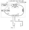
- FIG. 2 shows an exemplary configuration of the waveguide.
- an excitation source 11A is connected by a wavelength division multiplexing unit 11B to a gain fiber 11C that contains rare earth element such as erbium (Er), and a photo-coupler 11D is connected at input port to the end of the gain fiber 11C.
- Er rare earth element
- a photo-coupler 11D is connected at input port to the end of the gain fiber 11C.
- An optical fiber OF1 is connected, at one end, to the first output port of the photo-coupler 11D, and at the other end, to a mode lock element 11E.
- the mode lock element 11E generates a pulse beam that is synchronized with the vertical mode of a transmitter and has a function of stabilizing the mode synchronization.
- An optical fiber OF2 is connected, at one end, to the second output port of the photo-coupler 11D, and at the other end, to the emitter 12.
- the pulse beam output from the gain fiber 11C is branched in the photo-coupler 11D and applied directly to the optical fiber OF2.
- the optical fiber OF2 guides the pulse beam to the emitter 12.
- the pulse beam output from the gain fiber 11C to the emitter 12 can therefore be prevented from propagating in a free space.
- An optical fiber OF3 is connected, at one end, to the third output port of the photo-coupler 11D, and at the other end, to the detector 13.
- the pulse beam output from the gain fiber 11C is branched in the photo-coupler 11D and introduced directly into the optical fiber OF3.
- the optical fiber OF3 guides the pulse beam to the detector 13.
- the pulse beam output from the gain fiber 11C to the detector 13 can therefore be prevented from propagating in the free space.
- photo-connectors CN are available, such as SC type, FC type, MU type, FC type and SMA type.
- Photo-connectors of any type adapted to the shape of fibers used are selected and used.
- the photo-coupler 11D may be a fused coupler in which optical fibers are fused and connected to have a tapered shape.
- the pulse beam output from the gain fiber 11C can be transmitted to the optical fibers OF2 and OF3 at the same time.
- the probe beam can be easily adjusted in terms of time with respect to the pump beam.
- optical fibers have characteristics of dispersing pulse beams, because their refractive indices change with the wavelength of the input pulse beam.
- the dispersion of the pulse beam is compensated for by a dispersion compensation unit constituted by an optical system composed of a prism, a grating, a chirped mirror, and the like.
- the dispersion of the pulse beam is compensated for, not by a dispersion compensation unit constituted by an optical system, but by the optical fibers OF2 and OF3.
- the optical fibers OF2 and OF3 include a plurality of optical fibers that exhibit different in beam-dispersing characteristic in a prescribed band. The optical fibers OF2 and OF3 can therefore compensate for the dispersion of the pulse beam output from the gain fiber 11C.
- optical fibers exhibiting a positive group velocity dispersion in the above-mentioned prescribed band (solid lines marked as "positive” in FIG. 3 ) and optical fibers exhibiting a negative group velocity dispersion in the prescribed band (solid lines marked as “negative” in FIG. 3 ) are alternately arranged and coupled with an optical connector (indicated by rectangles in FIG. 3 ), thus forming the optical fibers OF2 and OF3.
- the "prescribed band” is based on the central wavelength of the input pulse beam output from the gain fiber 11C in the ultra-short pulse fiber laser 11. At the input and output ends of each optical fiber thus made (OF2 or OF3), the pulse beam has the same pulse width.
- optical fibers exhibiting a positive group velocity dispersion and the optical fibers exhibiting a negative group velocity dispersion have the same length, and are alternately arranged and coupled together, providing the optical fibers OF2 and OF3.
- This invention is not limited to this configuration.
- These optical fibers may be coupled together in any other manners, in accordance with the characteristics of the fiber materials used, the length of fibers and the dispersion temperature, so long as the optical fibers OF2 and OF3 compensate for the dispersion of the pulse beam.
- any dispersion compensation unit that is physically independent need not be used.
- the time at which the probe beam reaches the detector 13 is delayed not by using a time delay unit having an external optical element such as a retro-reflector, but by applying a temperature load to the optical fiber OF3.
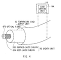
- the optical fiber OF3 is cover with a sheath unit 20.
- the sheath unit 20 is composed of a deep-layer sheath 20A and a surface-layer sheath 20B mounted on the deep-layer sheath 20A.
- the deep-layer sheath 20A is made of plastic or the like, and the surface-layer sheath 20B is made of nylon or the like. Made of these materials, the deep-layer sheath 20A and surface-layer sheath 20B impart mechanical strength and water resistance to the optical fiber OF3.
- the surface-layer sheath 20B of the sheath unit 20 is covered, in part or entirety, with a temperature load supply unit 30.
- the temperature load supply unit 30 applies a temperature load set by the load varying unit 14A incorporated in the computer 14.
- the optical fiber OF3 is thereby maintained at a temperature lower than the optical fiber OF2.
- the optical fiber OF3 is coupled to compensate for the dispersion at the constant temperature maintained by the temperature load supply unit 30.
- the temperature load supply unit 30 functions as a time delay unit.
- the pulse beam (probe beam) distributed from the photo-coupler 11D to the optical fiber OF3 therefore reaches the detector 13, delayed with respect to the pulse beam (pump beam) distributed from the photo-coupler 11D to the optical fiber OF2.
- a single-mode optical fiber is shown in FIG. 4 . Nonetheless, a multi-mode fiber can be adjusted in time delay, in the same way as the single-mode optical fiber is adjusted in time delay.
- the time at which the probe beam reaches the detector 13 is delayed by applying a temperature load to the optical fiber OF3. Therefore, any independent time delay unit that is physically independent need not be used.
- the optical fiber OF2 is coupled by the photo-coupler 11D to the gain fiber 11C provided in the ultra-short pulse fiber laser 11.
- the pulse beam (pump beam) output from the gain fiber 11C through the optical fiber OF2 is guided to the emitter 12 ( FIG. 2 ).
- the pulse beam (pump beam) can thus be introduced into the optical fiber OF2 through the ultra-short pulse fiber laser 11, without using an optical lens.
- the terahertz spectrometer 10 can therefore be smaller than in the case an optical lens is used.
- the pulse beam output from the ultra-short pulse fiber laser 11 to the emitter 12 can be prevented from propagating in a free space. As a result, the measuring accuracy can be increased by a decrease in the attenuation of the pulse beam.
- the optical fiber OF2 is composed of a plurality of optical fibers exhibiting different in dispersing characteristics in a prescribed frequency band and coupled to one another, so that the dispersion of the pulse beam output from the gain fiber 11C may be compensated for ( FIG. 3 ).
- the terahertz spectrometer 10 can therefore accomplish the compensation of dispersion, without using a dispersion compensation unit composed of external optical elememts.
- the terahertz spectrometer 10 can be smaller than in the case where a dispersion compensation unit is used.
- the maintenance cost can be greatly reduced than in the case where a dispersion compensation unit is used.
- the compensation of dispersion can be easily adjusted as needed when the central wavelength of the laser is changed.
- the optical fiber OF3 is coupled directly to the photo-coupler 11D and guides the pulse beam (probe beam) output from the gain fiber 11C to the detector 13 through the optical fiber OF3 ( FIG. 2 ).
- the terahertz spectrometer 10 has a time adjustment unit (i.e., temperature load supply unit 30 and load varying unit 14A) that applies a temperature load to a part or entirety of the optical fiber OF3 so that the optical fiber OF 3 may remain at a lower temperature than the optical fiber OF2 ( FIG. 4 ).
- the pulse beam (probe beam) can be introduced into the optical fiber OF3 from the ultra-short pulse fiber laser 11, without using an optical lens and can delay the time at which the pulse beam (probe beam) reaches the detector 13, without using an optical lens such as a retro-reflector lens.
- the terahertz spectrometer 10 can therefore be much smaller than in the case such an optical lens is used.
- the pulse beam output can be prevented from propagating in a free space extending from the ultra-short pulse fiber laser 11 to the detector 13. As a result, the measuring accuracy can be increased by a decrease in the attenuation of the pulse beam.
- the embodiment can realize a terahertz spectrometer 10 that can be small because the waveguides, one extending from the ultra-short pulse fiber laser 11 to the emitter 12 and the other extending from the ultra-short pulse fiber laser 11 to the detector 13, are optical fibers.
- the optical fiber OF3 is branched directly from the gain fiber 11C.
- the present invention is not limited to this, nevertheless.
- the optical fiber OF3 may be branched from the optical fiber OF2.
- a photo-coupler or a splitter
- the same advantage can be attained as in the case where the optical fiber OF3 is branched directly from the gain fiber 11C.
- the temperature load supply unit 30 covers the sheath unit 20 that in turn covers the optical fiber OF3.
- This invention is not limited to this. Instead, the temperature load supply unit 30 covers the deep-layer sheath 20A of the sheath unit 20. Alternatively, the temperature load supply unit 30 may directly cover the optical fiber OF3. In this case, the sheath unit 20 can be dispensed with, in part or in entirety. This can render the terahertz spectrometer 10 further smaller.
- the position where the temperature load is applied is the optical fiber OF3.
- the temperature load may be applied to the optical fiber OF2.
- the temperature load is one that has been set by the load varying unit 14A incorporated in the computer 14 and keeps the optical fiber OF3 at high a temperature.
- the same advantage is achieved as in the embodiment described above. That is, if the time at which the pulse beam reaches the detector 13 after passing through a waveguide is delayed with respect to the time at which the beam reaches the emitter 12 from the photo-coupler 11D (i.e., photo-coupler provided on the waveguide of the optical fiber OF2), the position of applying the temperature load can be changed, as needed.
- the load may be applied to one or both of the waveguides.
- the temperature is applied as the load in the embodiment described above. Instead, any other type of load, such as pressure, electric field or commercial fiber delay system may be applied.
- the optical fiber to be applied with a load is applied with a load so that it may remain in a "unique" loaded state different from the state in which any other optical fiber to be not applied with a load.
- This invention is not limited to this, nevertheless.
- the load may be switched so that the optical fiber may be loaded in "selected" one of various states. If this is the case, the time at which the pulse beam reaches the detector 13 can be switched. As a result, the measuring accuracy can be increased.
- the ultra-short pulse fiber laser 11 shown in FIG. 2 is used as an ultra-short pulse oscillator.
- This invention is not limited to this. Any one of the other various ultra-short pulse oscillators can be used instead.
- the present invention can be utilized in various technical fields such as industry, medical care, biotechnology, agriculture, security, data communication and electronics.
Landscapes
- Physics & Mathematics (AREA)
- Spectroscopy & Molecular Physics (AREA)
- General Physics & Mathematics (AREA)
- Health & Medical Sciences (AREA)
- Life Sciences & Earth Sciences (AREA)
- Biophysics (AREA)
- Ophthalmology & Optometry (AREA)
- Engineering & Computer Science (AREA)
- Biomedical Technology (AREA)
- Heart & Thoracic Surgery (AREA)
- Medical Informatics (AREA)
- Molecular Biology (AREA)
- Surgery (AREA)
- Animal Behavior & Ethology (AREA)
- General Health & Medical Sciences (AREA)
- Public Health (AREA)
- Veterinary Medicine (AREA)
- Investigating Or Analysing Materials By Optical Means (AREA)
- Spectrometry And Color Measurement (AREA)
- Optical Modulation, Optical Deflection, Nonlinear Optics, Optical Demodulation, Optical Logic Elements (AREA)
Applications Claiming Priority (1)
| Application Number | Priority Date | Filing Date | Title |
|---|---|---|---|
| JP2008053804A JP2009210423A (ja) | 2008-03-04 | 2008-03-04 | テラヘルツ分光装置 |
Publications (2)
| Publication Number | Publication Date |
|---|---|
| EP2098839A2 true EP2098839A2 (fr) | 2009-09-09 |
| EP2098839A3 EP2098839A3 (fr) | 2010-12-15 |
Family
ID=40688442
Family Applications (1)
| Application Number | Title | Priority Date | Filing Date |
|---|---|---|---|
| EP20090003036 Withdrawn EP2098839A3 (fr) | 2008-03-04 | 2009-03-03 | Spectromètre à térahertz |
Country Status (5)
| Country | Link |
|---|---|
| US (1) | US8179527B2 (fr) |
| EP (1) | EP2098839A3 (fr) |
| JP (1) | JP2009210423A (fr) |
| KR (1) | KR20090095464A (fr) |
| CN (1) | CN101526398B (fr) |
Cited By (1)
| Publication number | Priority date | Publication date | Assignee | Title |
|---|---|---|---|---|
| EP3043167A1 (fr) * | 2015-01-08 | 2016-07-13 | Hamamatsu Photonics K.K. | Appareil d'acquisition de forme d'onde temporelle térahertz |
Families Citing this family (8)
| Publication number | Priority date | Publication date | Assignee | Title |
|---|---|---|---|---|
| KR101067368B1 (ko) * | 2009-11-12 | 2011-09-23 | 한국과학기술원 | 광섬유 인듐비소 박막 테라헤르츠파 발생 장치 및 제조 방법 |
| US8642964B2 (en) * | 2010-08-31 | 2014-02-04 | The United States of America, as represented by the Secretary of Commerce, NIST | High repetition rate photoconductive terahertz emitter using a radio frequency bias |
| US9696206B2 (en) | 2011-03-29 | 2017-07-04 | Hamamatsu Photonics K.K. | Terahertz-wave spectrometer |
| US9080913B2 (en) * | 2011-03-29 | 2015-07-14 | Hamamatsu Photonics K.K | Terahertz-wave spectrometer and prism member |
| JP2013068526A (ja) * | 2011-09-22 | 2013-04-18 | Aisin Seiki Co Ltd | テラヘルツ波発生検出装置 |
| CN105737984A (zh) * | 2016-04-29 | 2016-07-06 | 深圳市太赫兹系统设备有限公司 | 太赫兹时域光谱辐射与检测装置 |
| JP6266719B1 (ja) * | 2016-08-31 | 2018-01-24 | フェムトディプロイメンツ株式会社 | テラヘルツ時間領域分光装置 |
| KR102738886B1 (ko) | 2021-12-02 | 2024-12-06 | 아주대학교산학협력단 | 완전 비표지자 바이오 센서 및 그 센서를 사용하는 테라헤르쯔 시간 기반 분광 장치 |
Citations (3)
| Publication number | Priority date | Publication date | Assignee | Title |
|---|---|---|---|---|
| US5710430A (en) * | 1995-02-15 | 1998-01-20 | Lucent Technologies Inc. | Method and apparatus for terahertz imaging |
| WO2001006915A1 (fr) | 1999-07-23 | 2001-02-01 | Teraview Limited | Sonde a rayonnement et detection de risque de caries |
| JP2008053804A (ja) | 2006-08-22 | 2008-03-06 | Namiki Precision Jewel Co Ltd | 携帯情報端末装置 |
Family Cites Families (7)
| Publication number | Priority date | Publication date | Assignee | Title |
|---|---|---|---|---|
| JPH085458A (ja) * | 1994-06-16 | 1996-01-12 | Yokogawa Electric Corp | 分光器 |
| EP0723168A3 (fr) | 1995-01-23 | 1998-07-15 | Siemens Aktiengesellschaft | Ligne à retard optique réglable |
| US6633379B2 (en) * | 2001-06-08 | 2003-10-14 | Semiconductor 300 Gmbh & Co. Kg | Apparatus and method for measuring the degradation of a tool |
| TWI276425B (en) * | 2005-03-23 | 2007-03-21 | Ind Tech Res Inst | System for detecting the burned degree of a skin |
| US20090190933A1 (en) * | 2006-06-02 | 2009-07-30 | Greg Fichter | Dispersion and nonlinear compensator for optical delivery fiber |
| JP4883350B2 (ja) * | 2006-06-29 | 2012-02-22 | アイシン精機株式会社 | テラヘルツ波発生・検出装置 |
| US7751713B2 (en) * | 2007-01-19 | 2010-07-06 | Infinera Corporation | Communication network with skew path monitoring and adjustment |
-
2008
- 2008-03-04 JP JP2008053804A patent/JP2009210423A/ja active Pending
-
2009
- 2009-02-09 KR KR20090010115A patent/KR20090095464A/ko not_active Withdrawn
- 2009-02-27 US US12/395,266 patent/US8179527B2/en not_active Expired - Fee Related
- 2009-03-03 EP EP20090003036 patent/EP2098839A3/fr not_active Withdrawn
- 2009-03-03 CN CN2009101260414A patent/CN101526398B/zh not_active Expired - Fee Related
Patent Citations (3)
| Publication number | Priority date | Publication date | Assignee | Title |
|---|---|---|---|---|
| US5710430A (en) * | 1995-02-15 | 1998-01-20 | Lucent Technologies Inc. | Method and apparatus for terahertz imaging |
| WO2001006915A1 (fr) | 1999-07-23 | 2001-02-01 | Teraview Limited | Sonde a rayonnement et detection de risque de caries |
| JP2008053804A (ja) | 2006-08-22 | 2008-03-06 | Namiki Precision Jewel Co Ltd | 携帯情報端末装置 |
Non-Patent Citations (1)
| Title |
|---|
| MOCHIZUKI K: "AUTOCORRELATION FUNCTION MEASUREMENTS WITH FIBRE INTERFEROMETERS", ELECTRONICS LETTERS, IEE STEVENAGE, GB, vol. 18, no. 19, 16 September 1982 (1982-09-16), pages 820/821, XP002065131, ISSN: 0013-5194 * |
Cited By (2)
| Publication number | Priority date | Publication date | Assignee | Title |
|---|---|---|---|---|
| EP3043167A1 (fr) * | 2015-01-08 | 2016-07-13 | Hamamatsu Photonics K.K. | Appareil d'acquisition de forme d'onde temporelle térahertz |
| US9417183B2 (en) | 2015-01-08 | 2016-08-16 | Hamamatsu Photonics K.K. | Terahertz wave temporal waveform acquistion apparatus |
Also Published As
| Publication number | Publication date |
|---|---|
| US20090225312A1 (en) | 2009-09-10 |
| CN101526398B (zh) | 2012-04-25 |
| CN101526398A (zh) | 2009-09-09 |
| US8179527B2 (en) | 2012-05-15 |
| JP2009210423A (ja) | 2009-09-17 |
| EP2098839A3 (fr) | 2010-12-15 |
| KR20090095464A (ko) | 2009-09-09 |
Similar Documents
| Publication | Publication Date | Title |
|---|---|---|
| US8179527B2 (en) | Terahertz spectrometer | |
| US9863815B2 (en) | Method and apparatus for multifrequency optical comb generation | |
| US8619355B2 (en) | Device for generating or receiving terahertz radiation | |
| US5963034A (en) | Electro-optic electromagnetic field sensor system with optical bias adjustment | |
| US20130146769A1 (en) | Optical pulse generating apparatus, terahertz spectroscopy apparatus, and tomography apparatus | |
| EP3315979B1 (fr) | Sonde électro-optique, appareil de mesure d'onde électromagnétique, et procédé de mesure d'onde électromagnétique | |
| WO2018223728A1 (fr) | Spectromètre térahertz tout-fibre dans le domaine temporel | |
| US20160377958A1 (en) | Terahertz wave generating apparatus and information obtaining apparatus | |
| Stanze et al. | High-speed coherent CW terahertz spectrometer | |
| EP4105619B1 (fr) | Dispositif de mesure spectroscopique | |
| US3644846A (en) | Optical modulation by submillimeter-wave signals and applications thereof | |
| EP3043167B1 (fr) | Appareil d'acquisition de forme d'onde temporelle térahertz | |
| JP2010237228A (ja) | テラヘルツ分光装置 | |
| JP2017009408A (ja) | 誘電分光装置 | |
| Ivanov et al. | Investigation of key components of photonic beamforming system for receiving antenna array | |
| Sukhov et al. | Microwave photonic detector for measuring pulsed electric field strengths in the sub-nanosecond region | |
| EP3671149A1 (fr) | Système et procédé de génération et de détection de rayonnement térahertzien | |
| JP3830847B2 (ja) | 光サンプリング装置 | |
| Ménager et al. | Optically-remoted probes for airborne RF sensors |
Legal Events
| Date | Code | Title | Description |
|---|---|---|---|
| PUAI | Public reference made under article 153(3) epc to a published international application that has entered the european phase |
Free format text: ORIGINAL CODE: 0009012 |
|
| 17P | Request for examination filed |
Effective date: 20090303 |
|
| AK | Designated contracting states |
Kind code of ref document: A2 Designated state(s): AT BE BG CH CY CZ DE DK EE ES FI FR GB GR HR HU IE IS IT LI LT LU LV MC MK MT NL NO PL PT RO SE SI SK TR |
|
| AX | Request for extension of the european patent |
Extension state: AL BA RS |
|
| PUAL | Search report despatched |
Free format text: ORIGINAL CODE: 0009013 |
|
| AK | Designated contracting states |
Kind code of ref document: A3 Designated state(s): AT BE BG CH CY CZ DE DK EE ES FI FR GB GR HR HU IE IS IT LI LT LU LV MC MK MT NL NO PL PT RO SE SI SK TR |
|
| AX | Request for extension of the european patent |
Extension state: AL BA RS |
|
| RIC1 | Information provided on ipc code assigned before grant |
Ipc: G01J 3/02 20060101ALI20101108BHEP Ipc: G01J 3/42 20060101AFI20090610BHEP |
|
| 17Q | First examination report despatched |
Effective date: 20101202 |
|
| AKX | Designation fees paid |
Designated state(s): DE FR GB |
|
| STAA | Information on the status of an ep patent application or granted ep patent |
Free format text: STATUS: THE APPLICATION IS DEEMED TO BE WITHDRAWN |
|
| 18D | Application deemed to be withdrawn |
Effective date: 20141001 |