EP2098876B1 - Procédé pour déterminer la distance de mesure minimale d'une antenne - Google Patents
Procédé pour déterminer la distance de mesure minimale d'une antenne Download PDFInfo
- Publication number
- EP2098876B1 EP2098876B1 EP07721176.1A EP07721176A EP2098876B1 EP 2098876 B1 EP2098876 B1 EP 2098876B1 EP 07721176 A EP07721176 A EP 07721176A EP 2098876 B1 EP2098876 B1 EP 2098876B1
- Authority
- EP
- European Patent Office
- Prior art keywords
- distance
- antenna
- mobile terminal
- tested
- electromagnetic scattering
- Prior art date
- Legal status (The legal status is an assumption and is not a legal conclusion. Google has not performed a legal analysis and makes no representation as to the accuracy of the status listed.)
- Active
Links
Images


Classifications
-
- G—PHYSICS
- G01—MEASURING; TESTING
- G01R—MEASURING ELECTRIC VARIABLES; MEASURING MAGNETIC VARIABLES
- G01R29/00—Arrangements for measuring or indicating electric quantities not covered by groups G01R19/00 - G01R27/00
- G01R29/08—Measuring electromagnetic field characteristics
- G01R29/10—Radiation diagrams of antennas
Definitions
- the present invention relates to a method for determining the antenna minimum measurement distance of a wireless mobile terminal, more specifically relates to a method for determining the antenna minimum measurement distance of a cellular mobile phone (referred to as mobile phone hereinafter).
- the present performance test technology of the mobile phone antenna do not consider how to test the performance of a mobile phone antenna in a real talking condition of a mobile phone, i.e. in a condition where "human" factors, for example, a mobile phone gets close to a human head or the head, neck, shoulder and etc. of a human body, are involved.
- the first step to solve the problem is to determine the performance test condition of the mobile phone antenna in the real talking condition, wherein the first condition is to determine the minimum measurement distance of a mobile phone antenna.
- the present invention aims to provide a method for determining the antenna minimum measurement distance of a wireless mobile terminal.
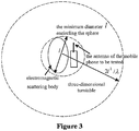
- the electromagnetic scattering dimension is the minimum diameter of a spherical surface encircling both the wireless mobile terminal under tested and the electromagnetic scattering body in the predetermined spatial area.
- the predetermined spatial area refers to a spherical surface spatial area determined with a diameter from 0.01 ⁇ to 0.1 ⁇ , wherein ⁇ is the wavelength of carrier wave.
- the step 102 comprises the following steps: putting the wireless mobile terminal under tested and the antenna thereof and a model of the electromagnetic scattering body on a test platform in a microwave anechoic chamber and connecting with a simulator through cables; connecting the radio frequency port of a standard antenna with the simulator through a radio frequency cable; configuring parameters of the simulator; and setting the back light of the wireless mobile terminal to be tested to the closed state or the darkest state and setting the wireless mobile terminal to be tested to the standby state.
- the cables are low-loss cables; the radio frequency cable is a low-power radio frequency cable; and the simulator is a network simulator.
- the electromagnetic scattering body in the predetermined spatial area is a human body and the electromagnetic scattering body comprises the head of the user of the wireless mobile terminal and further comprises the shoulder of the user of the wireless mobile terminal.
- electromagnetic scattering dimension of the mobile phone antenna and the electromagnetic scattering body in the predetermined spatial area is determined and measured in a simulated network environment in an electric wave anechoic chamber, and parameters of the minimum measurement distance of the mobile phone antenna can be calculated and obtained.
- the method has low requirement on environment and is easy to be tested and convenient to be carried out.
- the mobile phone to be tested and the antenna thereof are processed according to the Black-box, that is, detailed process of the mobile phone to be tested and the antenna thereof will be not involved.
- Preferred embodiments of the present invention will be illustrated in combination with the accompanying drawings in details as follows. If not conflict, the embodiments and the technical features of the embodiments can be combined with each other.
- Figure 1 is a flowchart of the method for determining the minimum measurement distance of a mobile phone antenna according to the embodiments of the invention
- Figure 2 is a schematic diagram of the definition of the antenna measurement radio communication link and the minimum measurement distance of a mobile phone antenna
- Figure 3 is a schematic diagram of determining electromagnetic scattering dimension of a mobile phone antenna to be tested and an electromagnetic scattering body in a predetermined spatial area. The procedure of Figure 3 will be described in details in combination with figures 1 and 2 .
- the method for determining the antenna minimum measurement distance of a wireless mobile terminal comprises the following steps: Step 102, establishing an antenna testing environment of a wireless mobile terminal to be tested.
- the following steps are included: putting the wireless mobile terminal under tested and the antenna thereof and a model of the electromagnetic scattering body on a test platform in a microwave anechoic chamber, and connecting with a simulator through cable; connecting the radio frequency port of a standard antenna with the simulator through radio frequency cable; configuring parameters of the simulator; setting the back light of the wireless mobile terminal to be tested to the closed state or the darkest state, and setting the wireless mobile terminal to be tested to the standby state.
- the electromagnetic scattering dimension is the minimum diameter of a virtual spherical surface encircling both the wireless mobile terminal under tested and the electromagnetic scattering body in the predetermined spatial area; preferably, the cable is low-loss cables; and the radio frequency cable is low-power radio frequency cable; and the simulator is preferably a network simulator.
- the step of configuring parameters of the simulator can be achieved by configuring the voice service to be a fixed voice service with a decided voice traffic.
- the model mensioned above comprises the mobile phone to be tested and the antenna thereof and an electromagnetic body model.
- the predetermined spatial area refers to a spatial area of a spherical surface determined with a diameter from 0.01 ⁇ to 0.1 ⁇ , wherein ⁇ is the wavelength of carrier wave.
- Step 104 determining electromagnetic scattering dimension of the antenna of the mobile terminal to be tested and the electromagnetic scattering body in a predetermined spatial area in the test environment, comprising:
- the above electromagnetic scattering body in the predetermined spatial area is a human body.
- the step 106 is carried out as follows:
- Step 106 can also be carried out in another way, comprising the following steps:
- figure 4 is a schematic diagram of the result of antenna measurement distance determined (electromagnetic body model 1: model of human head) and figure 5 is a schematic diagram of the result of antenna measurement distance determined (electromagnetic body model 2: model of human head and shoulder).
- the broken line shows the measurement result which is obtained without taking the existence of a human head into consideration.
- the real line shows the measurement result which is obtained when take the existence a human head into consideration. It can be seen from the figure that the dashdotted lines (the bigger one) should be taken as the result in the circs of the electromagnetic body model 1.
- the electromagnetic scattering dimension is the minimum diameter of a spherical surface encircling the wireless mobile terminal to be tested and the electromagnetic scattering body in the predetermined spatial area.
- the predetermined spatial area refers to a spherical surface spatial area determined with a diameter from 0.01 ⁇ to 0.1 ⁇ , wherein ⁇ is the wavelength of carrier wave; cables are low-loss cables; the radio frequency cable is a low-power radio frequency cable; and the simulator is a network simulator.
- the electromagnetic scattering body in the predetermined spatial area is a human body and the electromagnetic scattering body comprises the head of the user of the wireless mobile terminal and further comprises the shoulder of the user of the wireless mobile terminal.
- electromagnetic scattering dimension of the mobile phone antenna and the electromagnetic scattering body in the predetermined spatial area is determined and measured in a simulated network environment in an electric wave anechoic chamber, and parameters of the minimum measurement distance of the mobile phone antenna can be calculated and obtained.
- the method has low requirement on environment and is easy to be tested and convenient to be carried out.
- a computer program and a computer program product thereof are provided.
- the computer program product comprises instructions for causing a processor to perform the processes illustrated above with refer to figures 1-5 .
Landscapes
- Physics & Mathematics (AREA)
- Electromagnetism (AREA)
- General Physics & Mathematics (AREA)
- Monitoring And Testing Of Transmission In General (AREA)
- Mobile Radio Communication Systems (AREA)
Claims (8)
- Procédé pour déterminer une distance de mesure entre un terminal mobile sans fil à tester et une antenne standard, comprenant les étapes suivantes :l'étape 102, d'établissement d'un environnement de test d'antenne d'un terminal mobile sans fil à tester ;l'étape 104, de détermination d'une dimension de diffusion électromagnétique de l'antenne du terminal mobile à tester et d'un corps de diffusion électromagnétique dans une zone spatiale prédéterminée dans l'environnement de test, dans lequel la dimension de diffusion électromagnétique est le diamètre minimal d'une surface sphérique entourant à la fois le terminal mobile sans fil testé et le corps de diffusion électromagnétique dans la zone spatiale prédéterminée ; etl'étape 106, de calcul de la distance minimale entre le terminal mobile à tester et une antenne standard en fonction de la dimension de diffusion électromagnétique déterminée,dans lequel l'étape 102 comprend les étapes suivantes :le fait de tester le terminal mobile sans fil et l'antenne du terminal mobile sans fil, et un modèle du corps de diffusion électromagnétique sur une plate-forme de test dans une chambre anéchoïque à hyperfréquences et la connexion de l'antenne standard à un simulateur au moyen de câbles ;la connexion d'un port radiofréquence de l'antenne standard au simulateur au moyen d'un câble radiofréquence ;la configuration de paramètres du simulateur ; etle réglage d'un rétro-éclairage du terminal mobile sans fil à tester à un état fermé ou à un état sombre, et le réglage du terminal mobile sans-fil à tester à un état de veille.
- Procédé selon la revendication 1, dans lequel la zone spatiale prédéterminée fait référence à une zone spatiale de surface sphérique déterminée avec un diamètre de 0,01 à 0,1, dans lequel est la longueur d'onde de l'onde porteuse.
- Procédé selon la revendication 1, dans lequel les câbles sont des câbles à faibles pertes.
- Procédé selon la revendication 1, dans lequel le câble radiofréquence est un câble radiofréquence de faible puissance.
- Procédé selon la revendication 1, dans lequel le simulateur est un simulateur de réseau.
- Procédé selon la revendication 1, dans lequel la configuration de paramètres du simulateur comprend :
la configuration du service vocal pour qu'il soit un service vocal avec un trafic vocal décidé. - Procédé selon la revendication 1, dans lequel l'étape 106 comprend les étapes suivantes :le calcul d'une première distance r1, d'une deuxième distance r2 et d'une troisième distance r3 en fonction de la dimension de diffusion électromagnétique ;la prise du maximum de la première distance, de la deuxième distance et de la troisième distance comme étant la distance minimale entre le terminal mobile à tester et l'antenne de mesure, dans lequel r1 = 2l2/, r2 = 3, r3 = 3l, l est la dimension de diffusion électromagnétique, et est la longueur d'onde de l'onde porteuse.
- Procédé selon la revendication 1, dans lequel l'étape 106 comprend les étapes suivantes :le calcul d'une première distance r1 et d'une deuxième distance r2 en fonction de la dimension de diffusion électromagnétique ;la prise du maximum de la première distance et de la deuxième distance comme étant la distance minimale entre le terminal mobile à tester et l'antenne de mesure, dans lequel r1 = 2l2/, r2 = 3, l est la dimension de diffusion électromagnétique, et est la longueur d'onde de l'onde porteuse.
Applications Claiming Priority (2)
| Application Number | Priority Date | Filing Date | Title |
|---|---|---|---|
| CNA2006101608753A CN1964547A (zh) | 2006-11-30 | 2006-11-30 | 确定天线最小测试距离的方法 |
| PCT/CN2007/001603 WO2008064544A1 (fr) | 2006-11-30 | 2007-05-17 | Procédé pour déterminer la distance de mesure minimale d'une antenne |
Publications (3)
| Publication Number | Publication Date |
|---|---|
| EP2098876A1 EP2098876A1 (fr) | 2009-09-09 |
| EP2098876A4 EP2098876A4 (fr) | 2013-10-09 |
| EP2098876B1 true EP2098876B1 (fr) | 2019-09-04 |
Family
ID=38083376
Family Applications (1)
| Application Number | Title | Priority Date | Filing Date |
|---|---|---|---|
| EP07721176.1A Active EP2098876B1 (fr) | 2006-11-30 | 2007-05-17 | Procédé pour déterminer la distance de mesure minimale d'une antenne |
Country Status (4)
| Country | Link |
|---|---|
| US (1) | US8395556B2 (fr) |
| EP (1) | EP2098876B1 (fr) |
| CN (2) | CN1964547A (fr) |
| WO (1) | WO2008064544A1 (fr) |
Families Citing this family (11)
| Publication number | Priority date | Publication date | Assignee | Title |
|---|---|---|---|---|
| CN101819237B (zh) * | 2010-04-08 | 2011-12-14 | 中国舰船研究设计中心 | 腔体结构周围电磁环境强度的判别方法 |
| FR2965931B1 (fr) * | 2010-10-08 | 2013-05-03 | Satimo Ind | Procede et dispositif de test electronique d'un objet |
| CN102508049A (zh) * | 2011-11-22 | 2012-06-20 | 西北工业大学 | 一种基于Hankel函数外推的天线中场测试方法 |
| CN103293392B (zh) * | 2012-02-29 | 2017-04-05 | 深圳光启创新技术有限公司 | 一种紧缩场产生装置 |
| CN103293395B (zh) * | 2012-02-29 | 2017-04-12 | 深圳光启创新技术有限公司 | 一种紧缩场产生装置 |
| CN103293394B (zh) * | 2012-02-29 | 2017-04-05 | 深圳光启创新技术有限公司 | 一种紧缩场产生装置 |
| CN103293393B (zh) * | 2012-02-29 | 2017-04-12 | 深圳光启创新技术有限公司 | 一种紧缩场产生装置 |
| CN102788908B (zh) * | 2012-07-24 | 2014-12-10 | 中国舰船研究设计中心 | 加载圆柱形鞭天线的舰船水平电磁散射均值预测方法 |
| CN103245841B (zh) * | 2013-04-28 | 2015-07-01 | 西北工业大学 | 一种基于球面近场扫描外推的天线方向图测试方法 |
| CN107966616B (zh) * | 2016-10-19 | 2021-06-11 | 郑州宇通客车股份有限公司 | 基于车体三维模型的电动车电磁场发射强度测试方法 |
| US11698401B1 (en) * | 2022-02-04 | 2023-07-11 | Rohde & Schwarz Gmbh & Co. Kg | Method of simulating an effect of interactions between a device under test and a scattering object and hybrid OTA test system |
Family Cites Families (15)
| Publication number | Priority date | Publication date | Assignee | Title |
|---|---|---|---|---|
| FR2797327B1 (fr) * | 1999-08-03 | 2001-11-09 | France Telecom | Procede et dispositif de mesure en champ proche de rayonnements radioelectriques non controles |
| US6329953B1 (en) * | 2000-09-29 | 2001-12-11 | Rangestar Wireless | Method and system for rating antenna performance |
| GB2373374B (en) * | 2001-03-15 | 2004-03-17 | Agilent Technologies Inc | Novel fiber optic transceiver module |
| US7035594B2 (en) * | 2001-07-02 | 2006-04-25 | Qualcomm Inc. | Method and apparatus for testing and evaluating wireless communication devices |
| CN1277115C (zh) * | 2001-08-08 | 2006-09-27 | 株式会社Ntt都科摩 | 吸收功率测量装置 |
| US6540414B1 (en) * | 2001-10-05 | 2003-04-01 | International Business Machines Corporation | Integrated optical coupler and housing arrangement |
| KR100449436B1 (ko) * | 2001-10-31 | 2004-09-21 | 주식회사 어필텔레콤 | 안테나 각도조절이 가능한 휴대폰 |
| CN1209635C (zh) * | 2002-12-03 | 2005-07-06 | 智邦科技股份有限公司 | 天线测试系统 |
| TWI246614B (en) * | 2003-06-20 | 2006-01-01 | Ind Tech Res Inst | Low-density wavelength division multiplexing light transmission module |
| FR2859023B1 (fr) * | 2003-08-18 | 2005-12-23 | Satimo Sa | Chambre anechoique a observation directe du comportement electromagnetique d'un outil a etudier |
| CN1308696C (zh) * | 2003-11-29 | 2007-04-04 | 富士康(昆山)电脑接插件有限公司 | 天线测试方法 |
| US7477877B2 (en) * | 2004-02-11 | 2009-01-13 | Sony Ericsson Mobile Communications Ab | GSM radiated sensitivity measurement technique |
| US7102562B2 (en) * | 2004-03-22 | 2006-09-05 | Motorola, Inc. | Radio frequency anechoic chamber with improved test stand |
| US7178996B2 (en) * | 2004-04-09 | 2007-02-20 | Jds Uniphase Corporation | High density optical transceiver |
| JP4489505B2 (ja) * | 2004-05-12 | 2010-06-23 | 株式会社エヌ・ティ・ティ・ドコモ | ウエイト決定装置及びウエイト決定方法 |
-
2006
- 2006-11-30 CN CNA2006101608753A patent/CN1964547A/zh active Pending
-
2007
- 2007-05-17 WO PCT/CN2007/001603 patent/WO2008064544A1/fr not_active Ceased
- 2007-05-17 US US12/516,345 patent/US8395556B2/en active Active
- 2007-05-17 EP EP07721176.1A patent/EP2098876B1/fr active Active
- 2007-11-16 CN CN2007101697569A patent/CN101231316B/zh active Active
Non-Patent Citations (1)
| Title |
|---|
| None * |
Also Published As
| Publication number | Publication date |
|---|---|
| CN101231316B (zh) | 2012-12-05 |
| WO2008064544A1 (fr) | 2008-06-05 |
| EP2098876A4 (fr) | 2013-10-09 |
| CN1964547A (zh) | 2007-05-16 |
| CN101231316A (zh) | 2008-07-30 |
| EP2098876A1 (fr) | 2009-09-09 |
| US20100109956A1 (en) | 2010-05-06 |
| US8395556B2 (en) | 2013-03-12 |
Similar Documents
| Publication | Publication Date | Title |
|---|---|---|
| EP2098876B1 (fr) | Procédé pour déterminer la distance de mesure minimale d'une antenne | |
| US8588763B2 (en) | Methods for testing wireless electronic devices using short message service | |
| US9319908B2 (en) | Methods for reducing path loss while testing wireless electronic devices with multiple antennas | |
| CN102386986B (zh) | 一种无线终端的ota性能的测试方法、装置及系统 | |
| US8513963B2 (en) | Radio frequency testing apparatus | |
| US20150177277A1 (en) | Radio-Frequency Test System with Tunable Test Antenna Circuitry | |
| US9069037B2 (en) | Methods for testing wireless electronic devices using automatic self-test mode | |
| JP2022506002A (ja) | アンテナアレイのリモート無線制御用の近接場アンテナ | |
| Quijano et al. | Optimization of a compact frequency-and environment-reconfigurable antenna | |
| CN114256595B (zh) | 一种电子设备 | |
| CN110514907B (zh) | 无线通信装置空中传输量测系统 | |
| Fady et al. | Novel miniaturized multiband antenna and applications for smart navigation media | |
| US12298871B2 (en) | Cellular-to-USB and cellular-to-DisplayPort SW mitigation | |
| CN101106792A (zh) | 用于无线视频终端的参数测量方法 | |
| Zhekov et al. | Over‐the‐Air Evaluation of User Body Loss for Popular In‐Ear Bluetooth Earbuds | |
| CN109041096B (zh) | 射频电路仿真方法及相关装置 | |
| CN208189772U (zh) | 车辆和车载天线系统 | |
| Huang et al. | Compact thirteen‐band antenna for 4G/5G/WLAN metal frame mobile phones | |
| Chen et al. | Low-frequency band metal rim antenna design using TCM for smartphone application | |
| Das et al. | Design and acceptance test of compact planar monopole antenna for lTE smartphone considering SAR, TRP, and HAC values | |
| Collins | Practical application of small antennas in hardware platforms | |
| Amin-Zadeh et al. | Inspecting safety level of bluetooth headset radiation in the vicinity of human head: A numerical study | |
| TW201414080A (zh) | 電子裝置 | |
| Visvesvaran et al. | Design and implementation of various antenna for smart watch applications | |
| Loh et al. | A rigorous measurement technique for radiation pattern characterisation of embedded wireless communication systems |
Legal Events
| Date | Code | Title | Description |
|---|---|---|---|
| PUAI | Public reference made under article 153(3) epc to a published international application that has entered the european phase |
Free format text: ORIGINAL CODE: 0009012 |
|
| 17P | Request for examination filed |
Effective date: 20090529 |
|
| AK | Designated contracting states |
Kind code of ref document: A1 Designated state(s): AT BE BG CH CY CZ DE DK EE ES FI FR GB GR HU IE IS IT LI LT LU LV MC MT NL PL PT RO SE SI SK TR |
|
| DAX | Request for extension of the european patent (deleted) | ||
| A4 | Supplementary search report drawn up and despatched |
Effective date: 20130910 |
|
| RIC1 | Information provided on ipc code assigned before grant |
Ipc: G01R 29/10 20060101AFI20130904BHEP Ipc: G01R 29/08 20060101ALI20130904BHEP |
|
| STAA | Information on the status of an ep patent application or granted ep patent |
Free format text: STATUS: EXAMINATION IS IN PROGRESS |
|
| 17Q | First examination report despatched |
Effective date: 20180130 |
|
| GRAP | Despatch of communication of intention to grant a patent |
Free format text: ORIGINAL CODE: EPIDOSNIGR1 |
|
| STAA | Information on the status of an ep patent application or granted ep patent |
Free format text: STATUS: GRANT OF PATENT IS INTENDED |
|
| INTG | Intention to grant announced |
Effective date: 20190327 |
|
| GRAS | Grant fee paid |
Free format text: ORIGINAL CODE: EPIDOSNIGR3 |
|
| GRAA | (expected) grant |
Free format text: ORIGINAL CODE: 0009210 |
|
| STAA | Information on the status of an ep patent application or granted ep patent |
Free format text: STATUS: THE PATENT HAS BEEN GRANTED |
|
| AK | Designated contracting states |
Kind code of ref document: B1 Designated state(s): AT BE BG CH CY CZ DE DK EE ES FI FR GB GR HU IE IS IT LI LT LU LV MC MT NL PL PT RO SE SI SK TR |
|
| REG | Reference to a national code |
Ref country code: GB Ref legal event code: FG4D |
|
| REG | Reference to a national code |
Ref country code: CH Ref legal event code: EP |
|
| REG | Reference to a national code |
Ref country code: AT Ref legal event code: REF Ref document number: 1176110 Country of ref document: AT Kind code of ref document: T Effective date: 20190915 |
|
| REG | Reference to a national code |
Ref country code: DE Ref legal event code: R096 Ref document number: 602007059154 Country of ref document: DE |
|
| REG | Reference to a national code |
Ref country code: IE Ref legal event code: FG4D |
|
| REG | Reference to a national code |
Ref country code: NL Ref legal event code: MP Effective date: 20190904 |
|
| REG | Reference to a national code |
Ref country code: LT Ref legal event code: MG4D |
|
| PG25 | Lapsed in a contracting state [announced via postgrant information from national office to epo] |
Ref country code: LT Free format text: LAPSE BECAUSE OF FAILURE TO SUBMIT A TRANSLATION OF THE DESCRIPTION OR TO PAY THE FEE WITHIN THE PRESCRIBED TIME-LIMIT Effective date: 20190904 Ref country code: FI Free format text: LAPSE BECAUSE OF FAILURE TO SUBMIT A TRANSLATION OF THE DESCRIPTION OR TO PAY THE FEE WITHIN THE PRESCRIBED TIME-LIMIT Effective date: 20190904 Ref country code: BG Free format text: LAPSE BECAUSE OF FAILURE TO SUBMIT A TRANSLATION OF THE DESCRIPTION OR TO PAY THE FEE WITHIN THE PRESCRIBED TIME-LIMIT Effective date: 20191204 Ref country code: SE Free format text: LAPSE BECAUSE OF FAILURE TO SUBMIT A TRANSLATION OF THE DESCRIPTION OR TO PAY THE FEE WITHIN THE PRESCRIBED TIME-LIMIT Effective date: 20190904 |
|
| PG25 | Lapsed in a contracting state [announced via postgrant information from national office to epo] |
Ref country code: LV Free format text: LAPSE BECAUSE OF FAILURE TO SUBMIT A TRANSLATION OF THE DESCRIPTION OR TO PAY THE FEE WITHIN THE PRESCRIBED TIME-LIMIT Effective date: 20190904 Ref country code: GR Free format text: LAPSE BECAUSE OF FAILURE TO SUBMIT A TRANSLATION OF THE DESCRIPTION OR TO PAY THE FEE WITHIN THE PRESCRIBED TIME-LIMIT Effective date: 20191205 Ref country code: ES Free format text: LAPSE BECAUSE OF FAILURE TO SUBMIT A TRANSLATION OF THE DESCRIPTION OR TO PAY THE FEE WITHIN THE PRESCRIBED TIME-LIMIT Effective date: 20190904 |
|
| REG | Reference to a national code |
Ref country code: AT Ref legal event code: MK05 Ref document number: 1176110 Country of ref document: AT Kind code of ref document: T Effective date: 20190904 |
|
| PG25 | Lapsed in a contracting state [announced via postgrant information from national office to epo] |
Ref country code: PL Free format text: LAPSE BECAUSE OF FAILURE TO SUBMIT A TRANSLATION OF THE DESCRIPTION OR TO PAY THE FEE WITHIN THE PRESCRIBED TIME-LIMIT Effective date: 20190904 Ref country code: NL Free format text: LAPSE BECAUSE OF FAILURE TO SUBMIT A TRANSLATION OF THE DESCRIPTION OR TO PAY THE FEE WITHIN THE PRESCRIBED TIME-LIMIT Effective date: 20190904 Ref country code: EE Free format text: LAPSE BECAUSE OF FAILURE TO SUBMIT A TRANSLATION OF THE DESCRIPTION OR TO PAY THE FEE WITHIN THE PRESCRIBED TIME-LIMIT Effective date: 20190904 Ref country code: AT Free format text: LAPSE BECAUSE OF FAILURE TO SUBMIT A TRANSLATION OF THE DESCRIPTION OR TO PAY THE FEE WITHIN THE PRESCRIBED TIME-LIMIT Effective date: 20190904 Ref country code: IT Free format text: LAPSE BECAUSE OF FAILURE TO SUBMIT A TRANSLATION OF THE DESCRIPTION OR TO PAY THE FEE WITHIN THE PRESCRIBED TIME-LIMIT Effective date: 20190904 Ref country code: PT Free format text: LAPSE BECAUSE OF FAILURE TO SUBMIT A TRANSLATION OF THE DESCRIPTION OR TO PAY THE FEE WITHIN THE PRESCRIBED TIME-LIMIT Effective date: 20200106 Ref country code: RO Free format text: LAPSE BECAUSE OF FAILURE TO SUBMIT A TRANSLATION OF THE DESCRIPTION OR TO PAY THE FEE WITHIN THE PRESCRIBED TIME-LIMIT Effective date: 20190904 |
|
| PG25 | Lapsed in a contracting state [announced via postgrant information from national office to epo] |
Ref country code: CZ Free format text: LAPSE BECAUSE OF FAILURE TO SUBMIT A TRANSLATION OF THE DESCRIPTION OR TO PAY THE FEE WITHIN THE PRESCRIBED TIME-LIMIT Effective date: 20190904 Ref country code: SK Free format text: LAPSE BECAUSE OF FAILURE TO SUBMIT A TRANSLATION OF THE DESCRIPTION OR TO PAY THE FEE WITHIN THE PRESCRIBED TIME-LIMIT Effective date: 20190904 Ref country code: IS Free format text: LAPSE BECAUSE OF FAILURE TO SUBMIT A TRANSLATION OF THE DESCRIPTION OR TO PAY THE FEE WITHIN THE PRESCRIBED TIME-LIMIT Effective date: 20200224 |
|
| REG | Reference to a national code |
Ref country code: DE Ref legal event code: R097 Ref document number: 602007059154 Country of ref document: DE |
|
| PLBE | No opposition filed within time limit |
Free format text: ORIGINAL CODE: 0009261 |
|
| STAA | Information on the status of an ep patent application or granted ep patent |
Free format text: STATUS: NO OPPOSITION FILED WITHIN TIME LIMIT |
|
| PG2D | Information on lapse in contracting state deleted |
Ref country code: IS |
|
| PG25 | Lapsed in a contracting state [announced via postgrant information from national office to epo] |
Ref country code: DK Free format text: LAPSE BECAUSE OF FAILURE TO SUBMIT A TRANSLATION OF THE DESCRIPTION OR TO PAY THE FEE WITHIN THE PRESCRIBED TIME-LIMIT Effective date: 20190904 Ref country code: IS Free format text: LAPSE BECAUSE OF FAILURE TO SUBMIT A TRANSLATION OF THE DESCRIPTION OR TO PAY THE FEE WITHIN THE PRESCRIBED TIME-LIMIT Effective date: 20200105 |
|
| 26N | No opposition filed |
Effective date: 20200605 |
|
| PG25 | Lapsed in a contracting state [announced via postgrant information from national office to epo] |
Ref country code: SI Free format text: LAPSE BECAUSE OF FAILURE TO SUBMIT A TRANSLATION OF THE DESCRIPTION OR TO PAY THE FEE WITHIN THE PRESCRIBED TIME-LIMIT Effective date: 20190904 |
|
| PG25 | Lapsed in a contracting state [announced via postgrant information from national office to epo] |
Ref country code: CH Free format text: LAPSE BECAUSE OF NON-PAYMENT OF DUE FEES Effective date: 20200531 Ref country code: LI Free format text: LAPSE BECAUSE OF NON-PAYMENT OF DUE FEES Effective date: 20200531 Ref country code: MC Free format text: LAPSE BECAUSE OF FAILURE TO SUBMIT A TRANSLATION OF THE DESCRIPTION OR TO PAY THE FEE WITHIN THE PRESCRIBED TIME-LIMIT Effective date: 20190904 |
|
| REG | Reference to a national code |
Ref country code: BE Ref legal event code: MM Effective date: 20200531 |
|
| PG25 | Lapsed in a contracting state [announced via postgrant information from national office to epo] |
Ref country code: LU Free format text: LAPSE BECAUSE OF NON-PAYMENT OF DUE FEES Effective date: 20200517 |
|
| PG25 | Lapsed in a contracting state [announced via postgrant information from national office to epo] |
Ref country code: IE Free format text: LAPSE BECAUSE OF NON-PAYMENT OF DUE FEES Effective date: 20200517 |
|
| PG25 | Lapsed in a contracting state [announced via postgrant information from national office to epo] |
Ref country code: BE Free format text: LAPSE BECAUSE OF NON-PAYMENT OF DUE FEES Effective date: 20200531 |
|
| PG25 | Lapsed in a contracting state [announced via postgrant information from national office to epo] |
Ref country code: TR Free format text: LAPSE BECAUSE OF FAILURE TO SUBMIT A TRANSLATION OF THE DESCRIPTION OR TO PAY THE FEE WITHIN THE PRESCRIBED TIME-LIMIT Effective date: 20190904 Ref country code: MT Free format text: LAPSE BECAUSE OF FAILURE TO SUBMIT A TRANSLATION OF THE DESCRIPTION OR TO PAY THE FEE WITHIN THE PRESCRIBED TIME-LIMIT Effective date: 20190904 Ref country code: CY Free format text: LAPSE BECAUSE OF FAILURE TO SUBMIT A TRANSLATION OF THE DESCRIPTION OR TO PAY THE FEE WITHIN THE PRESCRIBED TIME-LIMIT Effective date: 20190904 |
|
| P01 | Opt-out of the competence of the unified patent court (upc) registered |
Effective date: 20230530 |
|
| PGFP | Annual fee paid to national office [announced via postgrant information from national office to epo] |
Ref country code: FR Payment date: 20250310 Year of fee payment: 19 |
|
| PGFP | Annual fee paid to national office [announced via postgrant information from national office to epo] |
Ref country code: GB Payment date: 20250327 Year of fee payment: 19 |
|
| PGFP | Annual fee paid to national office [announced via postgrant information from national office to epo] |
Ref country code: DE Payment date: 20250325 Year of fee payment: 19 |