EP2098877B1 - Verfahren, Vorrichtung und Anlage zur Fehlerlokalisierung in einer elektrischen Verbindung - Google Patents
Verfahren, Vorrichtung und Anlage zur Fehlerlokalisierung in einer elektrischen Verbindung Download PDFInfo
- Publication number
- EP2098877B1 EP2098877B1 EP08290221.4A EP08290221A EP2098877B1 EP 2098877 B1 EP2098877 B1 EP 2098877B1 EP 08290221 A EP08290221 A EP 08290221A EP 2098877 B1 EP2098877 B1 EP 2098877B1
- Authority
- EP
- European Patent Office
- Prior art keywords
- link
- defect
- electric
- signal
- variation
- Prior art date
- Legal status (The legal status is an assumption and is not a legal conclusion. Google has not performed a legal analysis and makes no representation as to the accuracy of the status listed.)
- Active
Links
Images




Classifications
-
- G—PHYSICS
- G01—MEASURING; TESTING
- G01R—MEASURING ELECTRIC VARIABLES; MEASURING MAGNETIC VARIABLES
- G01R31/00—Arrangements for testing electric properties; Arrangements for locating electric faults; Arrangements for electrical testing characterised by what is being tested not provided for elsewhere
- G01R31/08—Locating faults in cables, transmission lines, or networks
- G01R31/11—Locating faults in cables, transmission lines, or networks using pulse reflection methods
-
- G—PHYSICS
- G01—MEASURING; TESTING
- G01R—MEASURING ELECTRIC VARIABLES; MEASURING MAGNETIC VARIABLES
- G01R31/00—Arrangements for testing electric properties; Arrangements for locating electric faults; Arrangements for electrical testing characterised by what is being tested not provided for elsewhere
- G01R31/08—Locating faults in cables, transmission lines, or networks
- G01R31/081—Locating faults in cables, transmission lines, or networks according to type of conductors
- G01R31/085—Locating faults in cables, transmission lines, or networks according to type of conductors in power transmission or distribution lines, e.g. overhead
-
- G—PHYSICS
- G01—MEASURING; TESTING
- G01R—MEASURING ELECTRIC VARIABLES; MEASURING MAGNETIC VARIABLES
- G01R31/00—Arrangements for testing electric properties; Arrangements for locating electric faults; Arrangements for electrical testing characterised by what is being tested not provided for elsewhere
- G01R31/08—Locating faults in cables, transmission lines, or networks
- G01R31/088—Aspects of digital computing
Definitions
- the present invention relates to a method, a device and an installation for locating a fault on an electrical connection.
- electrical connection is meant a connection comprising an electric cable or a plurality of electrical cables connected together.
- the invention applies in particular to the location of defects in electrical energy transmission cables in connections including, for example, submarine and / or underground electrical cables, for which it is difficult to intervene and therefore necessary to obtain a precise and reliable location.
- the invention relates to a method comprising the steps of transmitting, at a first instant, an electrical signal with a predetermined propagation speed from one end of the electrical connection, and detecting, at a second instant, the reception an echo of this electrical signal.
- a pulse signal is first transmitted at a first end of a cable having a fault. Then successive echoes, due to multiple reflections of the pulse signal on the fault after several trips between the first end and the fault, are received and displayed on the screen of an oscilloscope.
- V propagation speed
- the x-axis can therefore be directly scaled in meters instead of microseconds since the speed of propagation of the pulse signal along the cable is known.
- the internal characteristics of the telecommunication network cable comprising the defect are very homogeneous over its entire length and the external medium has no influence on the propagation inside the cable, so that the speed of propagation of the pulse signal in the cable can be considered as known and constant.
- an operator is able to read directly on the oscilloscope, without additional calculation, the distance L between the first end of the cable and the defect.
- a method according to the invention further comprises a step of defining, using the variation model of the propagation speed of the electrical signal in the electrical connection, a table of correspondence between, of on the one hand, difference values between the first and second instants and, on the other hand, assumed distances from the defect at a reference point of the electrical connection.
- the variation model of the propagation speed of the electrical signal in the electrical connection is a dielectric loss factor and dielectric permittivity model of an insulator of the variable link as a function of a signal frequency. , and therefore the length of electrical connection traveled by the signal, inducing a decrease in the speed of propagation of the signal.
- the reception, at the second instant, of the echo of the electrical signal is determined when the amplitude of this echo reaches a predetermined percentage, in particular ten percent, of its maximum amplitude. This facilitates the reading and therefore improves the accuracy of the detection of the reception.
- the measurements, at several points along the connection, of at least a part of the components of the electromagnetic field are carried out along a path consisting of successive transverse passages in line with the connection, in particular according to a drawn in boustrophedon.
- the measured electromagnetic field is generated by the circulation in the electrical connection of a predetermined frequency current and in which the measured portion of the electromagnetic field components is filtered using a pass filtering system. -band set around this predetermined frequency of the current.
- the invention also relates to an installation for locating a fault on an electrical link, comprising an electrical link having a fault and two locating devices according to the invention respectively connected to two different ends of the link.
- First aspect of the invention localization or pre-localization of a defect by echometry
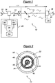
- the installation 10 of electric power transmission of the figure 1 comprises an electrical connection comprising two electric cables 12 and 14 connected together end to end.
- the cable 12 is an underground cable
- the cable 14 is an underwater cable.
- this installation schematically and partially illustrates a bi-pole of the IFA2000 link, of which a first end 16, called the Sellindge end, is located in the United Kingdom and whose second end 18, said end of Sangatte, is located in France.
- the cables 12 and 14 are connected to each other by means of a junction 20, called the Folkestone junction, located in Great Britain.
- a bi-pole of the IFA2000 link has two pairs of cables such as the set consisting of cables 12 and 14, but the simplified representation of the figure 1 is sufficient to understand the principle of the invention.
- the submarine cable 14 approximately 44.6 kilometers long, connects the end of Sangatte 18 to the junction of Folkestone 20.
- a method of locating this defect comprises injecting a pulse signal into the electrical connection and detecting the return of an echo of this signal after reflection on the defect. Since the Folkestone junction can not be opened, it is possible to inject this pulse signal only from the end of Sellindge 16 or Sangatte 18.
- At least one location device 28 is connected to the installation, either at the end Sellindge 16, or at the end of Sangatte 18, or at each of these two ends.
- two locating devices 28 are respectively connected to both ends 16 and 18.
- the set consisting of the storage means 34 and the computer 36 may in practice be a simple computer capable of controlling the generator 30 and processing signals provided by the receiver 32.
- the assembly consisting of the generator 30 and the receiver 32 may be in practice a classic echometer.
- each location device 28 may consist of a computer controlled echometer.
- the submarine cable 14 generally cylindrical in shape, is shown in section at the defect 26. It comprises a conductive core 40, for example copper, surrounded by an internal semiconductor 42, then an insulator 44 for the IFA2000 link, paper tape impregnated with oil. The insulator 44 is itself also surrounded by an external semiconductor 46.
- the internal semiconductor 42 is for example made of paper ribbons loaded with carbon and the external semiconductor 46 of metallized fabric.
- This assembly is surrounded by a conductive screen 48, for example lead, then a sheath 50, and finally a steel armor 52 for the holding and the mechanical protection of the cable 14.
- the fault 26 appears when the insulator 44 no longer performs its function correctly, so that a portion of the current carried passes between the conductive core 40 and the screen 48. This axial current passage burns the insulation 44 and then makes a short circuit between the core and the screen.
- Cable 14 Cable 12 Diameter on conductor (mm) 35 40.2 Resistivity of the conductor ( ⁇ .m) 1.7241.10 -8 1.7241.10 -8 Diameter of the central channel (mm) 20 Diameter on external screen (mm) 68.8 67.8 Thickness of the screen (mm) 3.2 3.1 Resistivity of the screen ( ⁇ .m) 21.4.10 -8 21.4.10 -8 Loss factor (x 10 -4 ) as a function of the frequency expressed in kHz 10 -2 20.9 19.5 3.2. 10 -2 27.6 26.4 10 -1 30.4 31.0 3.2.
- measurements made on the cables 12 and 14 also show that the dielectric permittivity of the insulator 44 varies correlatively with the loss factor.
- a signal is depleted of its high frequency components, so that the response of the dielectric is not constant as a function of the distance traveled by the signal.
- the dielectric losses decrease with the distance traveled by the signal, but correlatively the dielectric permittivity of the insulation increases inducing, at the same time, a decrease in the speed of propagation of the signal.
- An estimation of the variation of the speed of propagation of a signal as a function of the distance traveled, in the cables 12 and 14, can be carried out by a purely analytical study, followed by a numerical resolution according to a chosen representation, for example a representation of Laplace or Fourier.
- the response ⁇ (x, t) of a cable, at a distance x from the origin of the emission and after a time t, to a signal can be considered as the sum over the entire frequency domain or puls (from 0 to ⁇ ) pulsations of particular sinusoidal solutions v ( ⁇ ) of the Chatist Equation.
- the response ⁇ (x, t) of the cable then comprises a frontal wave and a signal tail, each spectral component not propagating with the same speed w ( ⁇ ).
- This frontal wave reproduces without distortion, but with a weakening, the emitted signal.
- the R, L and G constants of the cable vary with the frequency.
- the variation of R and L with the frequency gives rise to a residual wave in the frontal wave, which therefore no longer reproduces the transmitted signal. It's the backflow of the current at the surface of the conductors, at the high frequencies, which is physically at the origin.
- the effects related to the loss G and the inductance L of the cable can not, alone, account for the actual measurable variations in the speed of propagation in the cable.
- a postulate is established to model the propagation of the signal, taking into account the necessary link between the variations, with the frequency, of the dielectric loss factor tg ( ⁇ ) of the insulation 44, and of the its dielectric permittivity ⁇ r, in a numerical resolution of the analytical model described above, making it possible to access the shape and characteristics of the echo and to report on the speed of propagation of the signal.
- Two possible numerical approaches, one according to a Laplace representation, the other according to a Fourier representation make it possible to solve the analytical model and provide slightly different results, to be compared with the measurements.
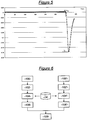
- FIG. figure 4a This results in several possible models of variation of the propagation velocity V in the submarine cable 14, as shown in FIG. figure 4a .
- a first model that using a Laplace representation
- a second model that using a Fourier representation
- a third model resulting from measurements made on the cable 14, is illustrated by a straight line.
- the propagation velocity at emission in the submarine cable 14, 152.6 m / ⁇ s, is known and is common to the three models.
- the propagation time is the time interval between the emission of the signal identified by its low rise time wavefront, and the reception of its echo on the defect, for example indicated by the foot ⁇ 0 of the " signal head 'with a rise time of several orders of magnitude higher.
- the foot of the echo ⁇ 0 presents a difficulty of localization, because of the strong attenuation of the components of higher rank of the signal and its echo on the defect.
- it can be identified by the study of the data relating to the amplitude of the echo, in particular the variation of curvature of the representative curve.
- the propagation time can be measured at the abscissa at 10% of maximum amplitude of the echo, denoted by ⁇ 10% as represented on FIG. figure 5 .
- the model of variation of the speed of propagation is obviously dependent on the chosen reference.
- V / 2 V 0 / 2 - The / ⁇ .
- V 0/2 is considered to be known, that is to say without uncertainty.
- the uncertainty of the relation (3) therefore lies in the slope 1 / ⁇ and in the measure ⁇ .
- .DELTA.L The 1 1 + ⁇ ⁇ ⁇ ⁇ ⁇ ⁇ ⁇ ⁇ + ⁇ ⁇ .
- Propagation velocity models based on a measurement of the propagation time at ⁇ 0 would show that there is no uncertainty in slope 1 / ⁇ and that only uncertainty exists in this case.
- the relation (3) can be directly constructed a correspondence table between the distance L of the defect 26 at a point reference and the total measured time of propagation of the transmitted signal and its echo back and forth. This table is stored in the storage means 34.
- the fault localization method 26 illustrated on the figure 6 is implemented in the installation of the figure 1 .
- an echo representative of the reflection of this signal on the fault 26 is detected, either automatically or manually by an operator.
- the instant ⁇ 0 or ⁇ 10% of reception of this echo is measured, either at the foot of the echo, or at 10% of the maximum amplitude of the echo, as indicated previously.
- an estimation step 104 the instant of reception of the echo is compared with the values of Table 1, in second or third column according to the measurement, to deduce, by correspondence, a cable segment of 400 meters. of length in which the defect 26 is located according to the measurement.
- a more accurate estimate of the position of the fault within the cable segment can be obtained by linear interpolation, according to a known calculation, as a function of the ends of this cable segment and the position of the measured moment of reception in the corresponding time segment of Table 1.
- the location can be made from the end Sellindge 16.
- the signal velocity V 0 of the signal is fixed and known.
- an echo representative of the reflection of this signal on the fault 26 is detected, either automatically or manually by an operator.
- the instant ⁇ 0 or ⁇ 10% of reception of this echo is measured, either at the foot of the echo, or at 10% of the maximum amplitude of the echo, as indicated previously.
- the instant of reception of the echo is compared with the values of Table 2, in second or third column according to the measurement, to deduce, by correspondence, a cable segment of 400 meters in length in which the defect 26 is located according to the measurement.
- a more accurate estimate of the fault position within the cable segment can be obtained by linear interpolation as a function of the ends of this cable segment and the position of the measured time of reception in the corresponding time segment of the array. 2.
- two locating devices can be arranged in the installation 10, each at one end, and the steps 100 to 106 on the one hand, and 100 'to 106' on the other hand, can be performed so as to obtain two estimated values of the location of the defect 26.
- the steps 106 and 106 ' are followed by an additional step 108 in which a definitive estimate of the location of the defect 26 can be deduced from the two values derived from steps 106 and 106 ', with possibly an estimated uncertainty in the form of a segment of the cable 14.
- a finer localization by study of the variations of the electromagnetic field above the submarine cable 14 can be conducted in the vicinity of the cable segment determined in step 108. Indeed, because of the presence of the fault 26 on the submarine cable 14, an electrical current signal i emitted at a certain frequency from one end of the cable in the conductive core 40 partially returns to its source, at the level of the defect 26, inter alia by the sea, thus creating an asymmetry between the emission end of the current and the defect 26, whereas beyond the defect this dissymmetry no longer exists.
- the frequency of the electrical signal emitted is for example between 25 and 80 Hz, avoiding frequencies around 50 Hz which correspond to the usual parasitic frequencies.
- This second aspect of the invention can be carried out by an installation such as that shown in FIG. figure 7 .
- An electromagnetic field measuring device 60 is disposed on a floating support 62, for example a boat, in the vicinity of the defect 26.
- the boat 62 moves, if possible along the cable 14, and a measurement of the field is recorded regularly.
- the electromagnetic field measuring device 60 comprises a GPS satellite positioning antenna 64 connected to a satellite positioning GPS detection unit GPS 66. This allows to know at every moment the exact position of the housing.
- the device 60 comprises three coils orthogonal to each other, making it possible to measure three orthogonal components of the electromagnetic field, so as to be able to deduce therefrom a value of the complete module
- the electromagnetic field component measurements by the three coils 68 are subjected to filtering, using three high-order bandpass filters 70 around the frequency of the emitted electrical signal.
- the result of these filterings is then submitted to a digital acquisition card 72.
- the geographical positioning values of the measuring device and electromagnetic field components are transmitted by the housing 66 and the acquisition card 72 to a computer 74 for the exploitation of these results.
- a power supply 76 supplies the housing 66, the filter system 70 and the computer 74 with electrical energy.
- the computer reconstructs a value of the
- the computer extracts the vertical component
- the fault localization principle 26 implemented by the device 60, and more particularly by the computer 74 is illustrated on the figure 9 .
- the electromagnetic field reaches a maximum in line with the cable.
- reaches a minimum above the cable 14.
- the electromagnetic field tends to decrease near the defect 26, then to cancel once the fault exceeded. Below the defect 26, the curve giving the value of the modulus of the field along the cable has a point of inflection which thus provides a good estimate of the location of the defect 26.
- the boat makes a path T consisting of successive transverse passages in line with the cable 14 along the selected cable segment 14, for example in a boustrophedon pattern, in particular following step 108 .
- the device 60 takes a series of measurements M of the electromagnetic field H.
- On the figure 11 is the module
- the passage over the cable 14 can be detected, either by a local maximum of the module
- measurements M are deduced therefrom the points of passage in line with the cable positioned along a straight line parallel to the x-axis of the figure 9 . Thanks to the measurements M taken at these points of passage, it is possible to form a curve of points, along the selected cable segment 14, for which a value of the module
- This point of inflection is determined by the computer 74 according to a conventional method which will not be detailed, during a step 204.
- step 200 consisting of following a path in a boustrophedon layout, can be dispensed with if the exact position of the cable is known and if it is possible to follow a journey directly along the cable at its right.
- step 202 measurements of the
- the invention is not limited to the embodiments described and illustrated. It is in particular susceptible to various variants, as to the installation of transmission of electrical energy to which it applies or to the propagation speed variation model used, that this model is deduced from measurements and / or a study. analytical and / or numerical analysis.
- Annex Table 1 Measure from the end of Sangatte 18 L (in m) ⁇ 0 (in ⁇ s) ⁇ 10% (in ⁇ s) 0.000 0 0 0400 5.20 Fast rise of the signal 0.800 10.43 10.65 1,200 15.68 16,05 1,600 20.95 21,47 2,000 26.24 26.92 2,400 31.54 32.37 2,800 36.86 37.84 3,200 42.19 43.31 3,600 47,54 48.79 4,000 52.88 54.28 4,400 58.21 59.77 4,800 63.58 65.26 5,200 68.94 70.76 5,600 74.32 76.26 6,000 79.7 81.76 6,400 85.08 87.27 6,800 90.47 92.78 7,200 95.88 98.29 7,600 101.27 103.81 8,000 106.65 109.33 8,400 112,05 114,84 8,800 117.45 120.36 9,200 122.84 125.88 9,600 128.23 131.41 10,000
Landscapes
- Physics & Mathematics (AREA)
- General Physics & Mathematics (AREA)
- Locating Faults (AREA)
Claims (10)
- Verfahren zur Lokalisierung eines Fehlers (26) in einer elektrischen Verbindung (12, 14), umfassend die Schritte, die darin bestehen:- Senden (100, 100'), in einem ersten Moment, eines elektrischen Signals mit vorbestimmter Ausbreitungsgeschwindigkeit am Start ab einem Ende (16, 18) der elektrischen Verbindung (12, 14),- Erkennen (102, 102'), in einem zweiten Moment, den Empfang eines Echos dieses elektrischen Signals,dadurch gekennzeichnet, dass es ferner die Schritte umfasst, die darin bestehen:- Festlegen eines Schwankungsmodells der Ausbreitungsgeschwindigkeit (V) des elektrischen Signals in der elektrischen Verbindung (12, 14) in Abhängigkeit von der von dem Signal durchlaufenen Länge der elektrischen Verbindung,- Schätzen (104, 104') einer Lokalisierung des Fehlers in Abhängigkeit von der Differenz zwischen dem ersten und zweiten Moment, der vorbestimmten Ausbreitungsgeschwindigkeit am Start und des Schwankungsmodells der Geschwindigkeit in der Verbindung (12, 14).
- Verfahren zur Lokalisierung eines Fehlers (26) in einer elektrischen Verbindung (12, 14) nach Anspruch 1, aufweisend einen Schritt, der darin besteht, mit Hilfe des Schwankungsmodells der Ausbreitungsgeschwindigkeit (V) des elektrischen Signals in der elektrischen Verbindung (12, 14) eine Übereinstimmungstabelle zwischen zum einen Differenzwerten zwischen dem ersten und zweiten Moment und zum anderen angenommenen Abständen des Fehlers (26) zu einem Bezugspunkt (16, 18, 20) der elektrischen Verbindung (12, 14) festzulegen.
- Verfahren zur Lokalisierung eines Fehlers (26) in einer elektrischen Verbindung (12, 14) nach Anspruch 1 oder 2, wobei das Schwankungsmodell der Ausbreitungsgeschwindigkeit (V) des elektrischen Signals in der elektrischen Verbindung (12, 14) ein Modell mit dielektrischem Verlustfaktor und dielektrischer Permittivität eines Isoliermaterials (44) der Verbindung (12, 14) ist, die in Abhängigkeit von einer Frequenz des Signals und folglich von der von dem Signal durchlaufenen Länge der elektrischen Verbindung schwanken, was zu einer Verringerung der Ausbreitungsgeschwindigkeit (V) des Signals führt.
- Verfahren zur Lokalisierung eines Fehlers (26) in einer elektrischen Verbindung (12, 14) nach einem der Ansprüche 1 bis 3, wobei der Empfang (102, 102'), im zweiten Moment, des Echos des elektrischen Signals bestimmt ist, wenn die Amplitude dieses Echos einen vorbestimmten Prozentsatz, insbesondere zehn Prozent, seiner maximalen Amplitude erreicht.
- Verfahren zur Lokalisierung eines Fehlers (26) in einer elektrischen Verbindung (12, 14) nach Anspruch 1, umfassend ferner die Schritte, die darin bestehen:- Messen (200) mindestens eines Teils der Komponenten eines elektromagnetischen Felds (H) in der Nähe der geschätzten Lokalisierung des Fehlers (26) an mehreren Stellen entlang der Verbindung (12, 14),- Ableiten (202) daraus einer Schätzung der Schwankung mindestens dieses Teils der Komponenten des elektromagnetischen Felds (H) entlang der elektrischen Verbindung (12, 14) in der Nähe der geschätzten Lokalisierung des Fehlers (26),- Schätzen (204) einer neuen Lokalisierung des Fehlers (26) in Abhängigkeit von der geschätzten Schwankung mindestens dieses Teils der Komponenten des elektromagnetischen Felds (H).
- Verfahren zur Lokalisierung eines Fehlers (26) in einer elektrischen Verbindung (12, 14) nach Anspruch 5, umfassend die Schritte, die darin bestehen:- Messen (200), mit Hilfe eines Systems (68) aus drei zueinander orthogonalen Spulen, des gesamten Moduls (|H|) des elektromagnetischen Felds in der Nähe der geschätzten Lokalisierung des Fehlers (26) an mehreren Stellen entlang der Verbindung (12, 14),- Ableiten (202) daraus einer Schätzung der Schwankung des gesamten Moduls (|H|) des elektromagnetischen Felds entlang der elektrischen Verbindung (12, 14) in der Nähe der geschätzten Lokalisierung des Fehlers (26),- Schätzen (204) einer neuen Lokalisierung des Fehlers (26) in Abhängigkeit von der Erkennung eines Krümmungspunkts innerhalb der geschätzten Schwankung des gesamten Moduls (|H|) des elektromagnetischen Felds entlang der Verbindung (12, 14).
- Verfahren zur Lokalisierung eines Fehlers (26) in einer elektrischen Verbindung (12, 14) nach Anspruch 5 oder 6, wobei die Messungen (M) an mehreren Stellen entlang der Verbindung (12, 14) mindestens eines Teils der Komponenten des elektromagnetischen Felds (H) gemäß einem Weg (T) durchgeführt werden, der von aufeinanderfolgenden transversalen Durchgängen senkrecht zu der Verbindung (12, 14), insbesondere gemäß einem furchenwendigen Verlauf, durchgeführt werden.
- Verfahren zur Lokalisierung eines Fehlers (26) in einer elektrischen Verbindung (12, 14) nach einem der Ansprüche 5 bis 7, wobei das gemessene elektromagnetische Feld (H) durch die Zirkulation in der elektrischen Verbindung (12, 14) eines Stroms (i) mit einer vorbestimmten Frequenz erzeugt wird und wobei der gemessene Teil der Komponenten des elektromagnetischen Felds (H) mit Hilfe eines um diese vorbestimmte Frequenz des Stroms (i) eingestellten Bandpassfiltersystems (70) gefiltert wird.
- Vorrichtung (28) zur Lokalisierung eines Fehlers (26) in einer elektrischen Verbindung (12, 14), die bestimmt ist, mit einem Ende (16, 18) der elektrischen Verbindung verbunden zu sein, umfassend:- einen Signalerzeuger (30) für das Senden (100, 100'), in einem ersten Moment, eines elektrischen Signals mit vorbestimmter Ausbreitungsgeschwindigkeit am Start ab einem Ende der elektrischen Verbindung (12, 14),- einen Signalempfänger (32) für das Erkennen (102, 102'), in einem zweiten Moment, des Empfangs eines Echos dieses elektrischen Signals,dadurch gekennzeichnet, dass sie ferner aufweist:- Speichermittel (34) von Daten eines Schwankungsmodells der Ausbreitungsgeschwindigkeit (V) des elektrischen Signals in der elektrischen Verbindung (12, 14) in Abhängigkeit von der von dem Signal durchlaufenen Länge der Verbindung,- einen Rechner (36), der konfiguriert ist, um eine Lokalisierung des Fehlers (26) mit Hilfe der gespeicherten Daten in Abhängigkeit von der Differenz zwischen dem ersten und zweiten Moment, der vorbestimmten Ausbreitungsgeschwindigkeit am Start und des Schwankungsmodells der Geschwindigkeit in der Verbindung (12, 14) zu schätzen.
- Anlage zur Lokalisierung eines Fehlers in einer elektrischen Verbindung, aufweisend eine elektrische Verbindung (12, 14), die einen Fehler (26) und zwei Lokalisierungsvorrichtungen (28) nach Anspruch 9 aufweist, die jeweils mit zwei unterschiedlichen Enden (16, 18) der Verbindung (12, 14) verbunden sind.
Priority Applications (9)
| Application Number | Priority Date | Filing Date | Title |
|---|---|---|---|
| EP08290221.4A EP2098877B1 (de) | 2008-03-07 | 2008-03-07 | Verfahren, Vorrichtung und Anlage zur Fehlerlokalisierung in einer elektrischen Verbindung |
| TR2018/10919T TR201810919T4 (tr) | 2008-03-07 | 2008-03-07 | Bir elektrik bağlantısı üzerinde bir arızanın yerinin saptanması için yöntem, cihaz ve donanım. |
| ES10159262.4T ES2687451T3 (es) | 2008-03-07 | 2008-03-07 | Procedimiento y dispositivo de localización de un fallo en una conexión electrica |
| EP10159262.4A EP2204659B1 (de) | 2008-03-07 | 2008-03-07 | Verfahren und Vorrichtung zur Fehlerlokalisierung in einer elektrischen Verbindung |
| ES08290221.4T ES2685744T3 (es) | 2008-03-07 | 2008-03-07 | Procedimiento, dispositivo e instalacion de localizacion de un fallo en una conexión electrica |
| TR2018/11114T TR201811114T4 (tr) | 2008-03-07 | 2008-03-07 | Bir elektrik bağlantısı üzerinde bir arızanın yerinin saptanması için yöntem ve cihaz |
| PCT/FR2009/050373 WO2009115747A2 (fr) | 2008-03-07 | 2009-03-06 | Procedes, dispositif et installation de localisation d'un defaut sur une liaison electrique |
| US12/867,788 US8554499B2 (en) | 2008-03-07 | 2009-03-06 | Methods, device and installation for locating a defect in an electric link |
| US14/013,764 US9081047B2 (en) | 2008-03-07 | 2013-08-29 | Methods, device and installation for locating a defect in an electric link |
Applications Claiming Priority (1)
| Application Number | Priority Date | Filing Date | Title |
|---|---|---|---|
| EP08290221.4A EP2098877B1 (de) | 2008-03-07 | 2008-03-07 | Verfahren, Vorrichtung und Anlage zur Fehlerlokalisierung in einer elektrischen Verbindung |
Related Child Applications (2)
| Application Number | Title | Priority Date | Filing Date |
|---|---|---|---|
| EP10159262.4A Division EP2204659B1 (de) | 2008-03-07 | 2008-03-07 | Verfahren und Vorrichtung zur Fehlerlokalisierung in einer elektrischen Verbindung |
| EP10159262.4A Division-Into EP2204659B1 (de) | 2008-03-07 | 2008-03-07 | Verfahren und Vorrichtung zur Fehlerlokalisierung in einer elektrischen Verbindung |
Publications (2)
| Publication Number | Publication Date |
|---|---|
| EP2098877A1 EP2098877A1 (de) | 2009-09-09 |
| EP2098877B1 true EP2098877B1 (de) | 2018-06-06 |
Family
ID=39579962
Family Applications (2)
| Application Number | Title | Priority Date | Filing Date |
|---|---|---|---|
| EP08290221.4A Active EP2098877B1 (de) | 2008-03-07 | 2008-03-07 | Verfahren, Vorrichtung und Anlage zur Fehlerlokalisierung in einer elektrischen Verbindung |
| EP10159262.4A Active EP2204659B1 (de) | 2008-03-07 | 2008-03-07 | Verfahren und Vorrichtung zur Fehlerlokalisierung in einer elektrischen Verbindung |
Family Applications After (1)
| Application Number | Title | Priority Date | Filing Date |
|---|---|---|---|
| EP10159262.4A Active EP2204659B1 (de) | 2008-03-07 | 2008-03-07 | Verfahren und Vorrichtung zur Fehlerlokalisierung in einer elektrischen Verbindung |
Country Status (5)
| Country | Link |
|---|---|
| US (2) | US8554499B2 (de) |
| EP (2) | EP2098877B1 (de) |
| ES (2) | ES2685744T3 (de) |
| TR (2) | TR201810919T4 (de) |
| WO (1) | WO2009115747A2 (de) |
Cited By (1)
| Publication number | Priority date | Publication date | Assignee | Title |
|---|---|---|---|---|
| RU2791677C1 (ru) * | 2022-05-18 | 2023-03-13 | Федеральное государственное бюджетное образовательное учреждение высшего образования "Кубанский государственный технологический университет" (ФГБОУ ВО "КубГТУ") | Устройство для определения места повреждения подводного кабеля |
Families Citing this family (9)
| Publication number | Priority date | Publication date | Assignee | Title |
|---|---|---|---|---|
| FR2951561B1 (fr) * | 2009-10-20 | 2011-12-09 | Areva T & D Sas | Procede de detection de la position d'un front d'onde correspondant a un evenement dans un signal recu par un detecteur |
| FR3000207B1 (fr) * | 2012-12-20 | 2015-07-17 | Soletanche Freyssinet | Procede et systeme pour surveiller un ouvrage de genie civil. |
| US10436928B2 (en) * | 2014-12-19 | 2019-10-08 | International Business Machines Corporation | Detection and imaging of subsurface high impedance contrast objects |
| CN104502806A (zh) * | 2015-01-09 | 2015-04-08 | 山东康威通信技术股份有限公司 | 基于架空电缆混合线路暂态量信号的故障定位系统及方法 |
| CN105553542A (zh) * | 2015-12-31 | 2016-05-04 | 中英海底系统有限公司 | 基于电磁感应原理的海底缆线故障点探测方法 |
| CN110543612B (zh) * | 2019-06-27 | 2023-04-07 | 浙江工业大学 | 一种基于单目视觉测量的集卡定位方法 |
| CN110618364A (zh) * | 2019-11-03 | 2019-12-27 | 西南交通大学 | 一种评估配电网xlpe电缆终端绝缘可靠性的方法 |
| CN114019324B (zh) * | 2021-11-02 | 2024-07-19 | 常熟理工学院 | 低压智能型断路器负载侧配电线绝缘在线检测传感装置及方法 |
| CN119001373B (zh) * | 2024-10-23 | 2024-12-27 | 吉林省远程电缆有限公司 | 一种对船用电缆在线绝缘监控的自动检测系统 |
Citations (2)
| Publication number | Priority date | Publication date | Assignee | Title |
|---|---|---|---|---|
| US20040004492A1 (en) * | 2002-07-02 | 2004-01-08 | Hsu Hsin Chou | Method of determining disconnection location in a circuit |
| US7336078B1 (en) * | 2003-10-04 | 2008-02-26 | Seektech, Inc. | Multi-sensor mapping omnidirectional sonde and line locators |
Family Cites Families (9)
| Publication number | Priority date | Publication date | Assignee | Title |
|---|---|---|---|---|
| CH386557A (fr) * | 1962-09-24 | 1965-01-15 | Privaco Electronic | Procédé de dépistage d'un défaut de ligne électrique et dispositif pour la mise en oeuvre de ce procédé |
| US4835478A (en) * | 1987-02-17 | 1989-05-30 | Haddon Merrill K | Method and apparatus for acoustic detection of faults in underground cables |
| FR2766274B3 (fr) * | 1997-07-11 | 1999-09-10 | Atermes | Procede de localisation de defauts sur un cable metallique et dispositif de mise en oeuvre de ce procede |
| FR2766576B1 (fr) * | 1997-07-23 | 1999-08-27 | Commissariat Energie Atomique | Dispositif d'analyse d'impulsion unique a pas variable |
| FR2784192A1 (fr) | 1998-10-01 | 2000-04-07 | Atermes | Procede de localisation de defauts sur un cable a ecran metallique et dispositif de mise en oeuvre de ce procede |
| US6777953B2 (en) * | 2001-01-24 | 2004-08-17 | General Dynamics (Otc) Aerospace, Inc. | Parallel arc fault diagnostic for aircraft wiring |
| US7332901B2 (en) * | 2005-04-15 | 2008-02-19 | Seektech, Inc. | Locator with apparent depth indication |
| US20080048669A1 (en) * | 2006-08-28 | 2008-02-28 | Dzulkifli Saul Scherber | Topological mapping using a conductive infrastructure |
| EP2104863B1 (de) * | 2007-01-17 | 2010-05-05 | International Business Machines Corporation | Verfahren zur bestimmung der derzeitigen rückwegintegrität in einer elektrischen einrichtung, die mit einer weiteren einrichtung verbunden oder verbindbar ist |
-
2008
- 2008-03-07 TR TR2018/10919T patent/TR201810919T4/tr unknown
- 2008-03-07 ES ES08290221.4T patent/ES2685744T3/es active Active
- 2008-03-07 EP EP08290221.4A patent/EP2098877B1/de active Active
- 2008-03-07 EP EP10159262.4A patent/EP2204659B1/de active Active
- 2008-03-07 ES ES10159262.4T patent/ES2687451T3/es active Active
- 2008-03-07 TR TR2018/11114T patent/TR201811114T4/tr unknown
-
2009
- 2009-03-06 WO PCT/FR2009/050373 patent/WO2009115747A2/fr not_active Ceased
- 2009-03-06 US US12/867,788 patent/US8554499B2/en not_active Expired - Fee Related
-
2013
- 2013-08-29 US US14/013,764 patent/US9081047B2/en not_active Expired - Fee Related
Patent Citations (2)
| Publication number | Priority date | Publication date | Assignee | Title |
|---|---|---|---|---|
| US20040004492A1 (en) * | 2002-07-02 | 2004-01-08 | Hsu Hsin Chou | Method of determining disconnection location in a circuit |
| US7336078B1 (en) * | 2003-10-04 | 2008-02-26 | Seektech, Inc. | Multi-sensor mapping omnidirectional sonde and line locators |
Cited By (1)
| Publication number | Priority date | Publication date | Assignee | Title |
|---|---|---|---|---|
| RU2791677C1 (ru) * | 2022-05-18 | 2023-03-13 | Федеральное государственное бюджетное образовательное учреждение высшего образования "Кубанский государственный технологический университет" (ФГБОУ ВО "КубГТУ") | Устройство для определения места повреждения подводного кабеля |
Also Published As
| Publication number | Publication date |
|---|---|
| US20100332163A1 (en) | 2010-12-30 |
| US8554499B2 (en) | 2013-10-08 |
| EP2098877A1 (de) | 2009-09-09 |
| US20140005962A1 (en) | 2014-01-02 |
| EP2204659B1 (de) | 2018-06-13 |
| WO2009115747A3 (fr) | 2010-06-17 |
| ES2685744T3 (es) | 2018-10-11 |
| TR201810919T4 (tr) | 2018-08-27 |
| WO2009115747A2 (fr) | 2009-09-24 |
| ES2687451T3 (es) | 2018-10-25 |
| US9081047B2 (en) | 2015-07-14 |
| TR201811114T4 (tr) | 2018-08-27 |
| EP2204659A1 (de) | 2010-07-07 |
Similar Documents
| Publication | Publication Date | Title |
|---|---|---|
| EP2204659B1 (de) | Verfahren und Vorrichtung zur Fehlerlokalisierung in einer elektrischen Verbindung | |
| CA2805422C (fr) | Localisation d'un defaut sur une section de ligne electrique hors tension | |
| EP2082247B1 (de) | Verfahren und einrichtung zum analysieren eines elektrischen kabelnetzes unter verwendung von pseudozufallssequenzen | |
| EP2614379B1 (de) | Verfahren und vorrichtung zur messung der physikalischen eigenschaften eines kabels, im besonderen der ausbreitungsgeschwindigkeit | |
| WO2016156259A1 (fr) | Procede de caracterisation d'un tronçon d'une ligne de transmission, en particulier tronçon correspondant a un connecteur ou une serie de connecteurs reliant un equipement de mesure a un cable | |
| EP2820436B1 (de) | Verfahren zur messung der alterung von elektrischen kabeln | |
| EP3262730B1 (de) | Steuerung eines blitzschutzsystems | |
| EP1452840A1 (de) | Fühlstandmessgerät für einen Kraftstofftank und System zum Messen der Kraftstoffmenge im Tank | |
| EP0177384A1 (de) | Vorrichtung zum Ermitteln und Lokalisieren eines Wassereintritts in eine akustische Unterswasserantenne | |
| EP0982577B1 (de) | Gerät zur Messung der Übersprechdämpfung zwischen optischen Fasern | |
| WO2012150232A1 (fr) | Dispositif et une methode de detection et de localisation d'un defaut sur un cable electrique coaxial a isolation gazeuse | |
| EP2896968B1 (de) | Lokalisierungsverfahren einer Impulsquelle in einem dispersivem Medium | |
| FR2766274A1 (fr) | Procede de localisation de defauts sur un cable metallique et dispositif de mise en oeuvre de ce procede | |
| FR2946149A1 (fr) | Procede d'analyse de cables electriques de grande longueur et de reseaux de cables electriques. | |
| EP3877773B1 (de) | System zur analyse von fehlern durch reflektometrie mit optimiertem dynamikbereich | |
| FR2784192A1 (fr) | Procede de localisation de defauts sur un cable a ecran metallique et dispositif de mise en oeuvre de ce procede | |
| EP3646045B1 (de) | Reflektometrisches system zur fehleranalyse in einer übertragungsleitung | |
| EP4241400B1 (de) | Empfangsvorrichtung und verfahren für schallwellen | |
| WO2003067782A1 (fr) | Amelioration aux prodedes de mesures echometriques sur une ligne et dispositif de mise en oeuvre | |
| FR3148090A1 (fr) | Système de mesure d'un courant électrique et dispositif de détection d'un courant électrique pour un tel système | |
| CA3041244C (fr) | Dispositif de detection pour surveiller la corrosion d'une structure, vehicule et procede | |
| CA3153911A1 (fr) | Systeme de localisation d'un defaut dans une partie souterraine d'un reseau electrique moyenne tension |
Legal Events
| Date | Code | Title | Description |
|---|---|---|---|
| PUAI | Public reference made under article 153(3) epc to a published international application that has entered the european phase |
Free format text: ORIGINAL CODE: 0009012 |
|
| AK | Designated contracting states |
Kind code of ref document: A1 Designated state(s): AT BE BG CH CY CZ DE DK EE ES FI FR GB GR HR HU IE IS IT LI LT LU LV MC MT NL NO PL PT RO SE SI SK TR |
|
| AX | Request for extension of the european patent |
Extension state: AL BA MK RS |
|
| 17P | Request for examination filed |
Effective date: 20100217 |
|
| AKX | Designation fees paid |
Designated state(s): AT BE BG CH CY CZ DE DK EE ES FI FR GB GR HR HU IE IS IT LI LT LU LV MC MT NL NO PL PT RO SE SI SK TR |
|
| 17Q | First examination report despatched |
Effective date: 20120824 |
|
| RAP1 | Party data changed (applicant data changed or rights of an application transferred) |
Owner name: RTE RESEAU DE TRANSPORT D'ELECTRICITE |
|
| GRAP | Despatch of communication of intention to grant a patent |
Free format text: ORIGINAL CODE: EPIDOSNIGR1 |
|
| STAA | Information on the status of an ep patent application or granted ep patent |
Free format text: STATUS: GRANT OF PATENT IS INTENDED |
|
| RIC1 | Information provided on ipc code assigned before grant |
Ipc: G01R 31/08 20060101ALI20180216BHEP Ipc: G01R 31/11 20060101AFI20180216BHEP |
|
| INTG | Intention to grant announced |
Effective date: 20180320 |
|
| RIN1 | Information on inventor provided before grant (corrected) |
Inventor name: AUCOURT, CHRISTIAN Inventor name: BOURGEAT, XAVIER Inventor name: SURDON, MATTHIEU |
|
| GRAS | Grant fee paid |
Free format text: ORIGINAL CODE: EPIDOSNIGR3 |
|
| GRAA | (expected) grant |
Free format text: ORIGINAL CODE: 0009210 |
|
| STAA | Information on the status of an ep patent application or granted ep patent |
Free format text: STATUS: THE PATENT HAS BEEN GRANTED |
|
| AK | Designated contracting states |
Kind code of ref document: B1 Designated state(s): AT BE BG CH CY CZ DE DK EE ES FI FR GB GR HR HU IE IS IT LI LT LU LV MC MT NL NO PL PT RO SE SI SK TR |
|
| REG | Reference to a national code |
Ref country code: GB Ref legal event code: FG4D Free format text: NOT ENGLISH |
|
| REG | Reference to a national code |
Ref country code: CH Ref legal event code: EP Ref country code: AT Ref legal event code: REF Ref document number: 1006696 Country of ref document: AT Kind code of ref document: T Effective date: 20180615 |
|
| REG | Reference to a national code |
Ref country code: IE Ref legal event code: FG4D Free format text: LANGUAGE OF EP DOCUMENT: FRENCH |
|
| REG | Reference to a national code |
Ref country code: DE Ref legal event code: R096 Ref document number: 602008055506 Country of ref document: DE |
|
| REG | Reference to a national code |
Ref country code: NL Ref legal event code: FP |
|
| REG | Reference to a national code |
Ref country code: ES Ref legal event code: FG2A Ref document number: 2685744 Country of ref document: ES Kind code of ref document: T3 Effective date: 20181011 |
|
| REG | Reference to a national code |
Ref country code: LT Ref legal event code: MG4D |
|
| PG25 | Lapsed in a contracting state [announced via postgrant information from national office to epo] |
Ref country code: SE Free format text: LAPSE BECAUSE OF FAILURE TO SUBMIT A TRANSLATION OF THE DESCRIPTION OR TO PAY THE FEE WITHIN THE PRESCRIBED TIME-LIMIT Effective date: 20180606 Ref country code: CY Free format text: LAPSE BECAUSE OF FAILURE TO SUBMIT A TRANSLATION OF THE DESCRIPTION OR TO PAY THE FEE WITHIN THE PRESCRIBED TIME-LIMIT Effective date: 20180606 Ref country code: LT Free format text: LAPSE BECAUSE OF FAILURE TO SUBMIT A TRANSLATION OF THE DESCRIPTION OR TO PAY THE FEE WITHIN THE PRESCRIBED TIME-LIMIT Effective date: 20180606 Ref country code: FI Free format text: LAPSE BECAUSE OF FAILURE TO SUBMIT A TRANSLATION OF THE DESCRIPTION OR TO PAY THE FEE WITHIN THE PRESCRIBED TIME-LIMIT Effective date: 20180606 Ref country code: NO Free format text: LAPSE BECAUSE OF FAILURE TO SUBMIT A TRANSLATION OF THE DESCRIPTION OR TO PAY THE FEE WITHIN THE PRESCRIBED TIME-LIMIT Effective date: 20180906 Ref country code: BG Free format text: LAPSE BECAUSE OF FAILURE TO SUBMIT A TRANSLATION OF THE DESCRIPTION OR TO PAY THE FEE WITHIN THE PRESCRIBED TIME-LIMIT Effective date: 20180906 |
|
| PG25 | Lapsed in a contracting state [announced via postgrant information from national office to epo] |
Ref country code: LV Free format text: LAPSE BECAUSE OF FAILURE TO SUBMIT A TRANSLATION OF THE DESCRIPTION OR TO PAY THE FEE WITHIN THE PRESCRIBED TIME-LIMIT Effective date: 20180606 Ref country code: HR Free format text: LAPSE BECAUSE OF FAILURE TO SUBMIT A TRANSLATION OF THE DESCRIPTION OR TO PAY THE FEE WITHIN THE PRESCRIBED TIME-LIMIT Effective date: 20180606 Ref country code: GR Free format text: LAPSE BECAUSE OF FAILURE TO SUBMIT A TRANSLATION OF THE DESCRIPTION OR TO PAY THE FEE WITHIN THE PRESCRIBED TIME-LIMIT Effective date: 20180907 |
|
| REG | Reference to a national code |
Ref country code: AT Ref legal event code: MK05 Ref document number: 1006696 Country of ref document: AT Kind code of ref document: T Effective date: 20180606 |
|
| PG25 | Lapsed in a contracting state [announced via postgrant information from national office to epo] |
Ref country code: AT Free format text: LAPSE BECAUSE OF FAILURE TO SUBMIT A TRANSLATION OF THE DESCRIPTION OR TO PAY THE FEE WITHIN THE PRESCRIBED TIME-LIMIT Effective date: 20180606 Ref country code: PL Free format text: LAPSE BECAUSE OF FAILURE TO SUBMIT A TRANSLATION OF THE DESCRIPTION OR TO PAY THE FEE WITHIN THE PRESCRIBED TIME-LIMIT Effective date: 20180606 Ref country code: SK Free format text: LAPSE BECAUSE OF FAILURE TO SUBMIT A TRANSLATION OF THE DESCRIPTION OR TO PAY THE FEE WITHIN THE PRESCRIBED TIME-LIMIT Effective date: 20180606 Ref country code: IS Free format text: LAPSE BECAUSE OF FAILURE TO SUBMIT A TRANSLATION OF THE DESCRIPTION OR TO PAY THE FEE WITHIN THE PRESCRIBED TIME-LIMIT Effective date: 20181006 Ref country code: EE Free format text: LAPSE BECAUSE OF FAILURE TO SUBMIT A TRANSLATION OF THE DESCRIPTION OR TO PAY THE FEE WITHIN THE PRESCRIBED TIME-LIMIT Effective date: 20180606 Ref country code: CZ Free format text: LAPSE BECAUSE OF FAILURE TO SUBMIT A TRANSLATION OF THE DESCRIPTION OR TO PAY THE FEE WITHIN THE PRESCRIBED TIME-LIMIT Effective date: 20180606 Ref country code: RO Free format text: LAPSE BECAUSE OF FAILURE TO SUBMIT A TRANSLATION OF THE DESCRIPTION OR TO PAY THE FEE WITHIN THE PRESCRIBED TIME-LIMIT Effective date: 20180606 |
|
| REG | Reference to a national code |
Ref country code: DE Ref legal event code: R097 Ref document number: 602008055506 Country of ref document: DE |
|
| PLBE | No opposition filed within time limit |
Free format text: ORIGINAL CODE: 0009261 |
|
| STAA | Information on the status of an ep patent application or granted ep patent |
Free format text: STATUS: NO OPPOSITION FILED WITHIN TIME LIMIT |
|
| PGFP | Annual fee paid to national office [announced via postgrant information from national office to epo] |
Ref country code: GB Payment date: 20190128 Year of fee payment: 12 Ref country code: IT Payment date: 20190321 Year of fee payment: 12 Ref country code: GB Payment date: 20190325 Year of fee payment: 12 |
|
| 26N | No opposition filed |
Effective date: 20190307 |
|
| PG25 | Lapsed in a contracting state [announced via postgrant information from national office to epo] |
Ref country code: SI Free format text: LAPSE BECAUSE OF FAILURE TO SUBMIT A TRANSLATION OF THE DESCRIPTION OR TO PAY THE FEE WITHIN THE PRESCRIBED TIME-LIMIT Effective date: 20180606 Ref country code: DK Free format text: LAPSE BECAUSE OF FAILURE TO SUBMIT A TRANSLATION OF THE DESCRIPTION OR TO PAY THE FEE WITHIN THE PRESCRIBED TIME-LIMIT Effective date: 20180606 |
|
| PGFP | Annual fee paid to national office [announced via postgrant information from national office to epo] |
Ref country code: TR Payment date: 20190301 Year of fee payment: 12 Ref country code: BE Payment date: 20190321 Year of fee payment: 12 Ref country code: NL Payment date: 20190321 Year of fee payment: 12 |
|
| PGFP | Annual fee paid to national office [announced via postgrant information from national office to epo] |
Ref country code: ES Payment date: 20190424 Year of fee payment: 12 |
|
| REG | Reference to a national code |
Ref country code: DE Ref legal event code: R119 Ref document number: 602008055506 Country of ref document: DE |
|
| PG25 | Lapsed in a contracting state [announced via postgrant information from national office to epo] |
Ref country code: MC Free format text: LAPSE BECAUSE OF FAILURE TO SUBMIT A TRANSLATION OF THE DESCRIPTION OR TO PAY THE FEE WITHIN THE PRESCRIBED TIME-LIMIT Effective date: 20180606 |
|
| REG | Reference to a national code |
Ref country code: CH Ref legal event code: PL |
|
| PG25 | Lapsed in a contracting state [announced via postgrant information from national office to epo] |
Ref country code: LU Free format text: LAPSE BECAUSE OF NON-PAYMENT OF DUE FEES Effective date: 20190307 |
|
| PG25 | Lapsed in a contracting state [announced via postgrant information from national office to epo] |
Ref country code: CH Free format text: LAPSE BECAUSE OF NON-PAYMENT OF DUE FEES Effective date: 20190331 Ref country code: DE Free format text: LAPSE BECAUSE OF NON-PAYMENT OF DUE FEES Effective date: 20191001 Ref country code: LI Free format text: LAPSE BECAUSE OF NON-PAYMENT OF DUE FEES Effective date: 20190331 |
|
| PG25 | Lapsed in a contracting state [announced via postgrant information from national office to epo] |
Ref country code: PT Free format text: LAPSE BECAUSE OF FAILURE TO SUBMIT A TRANSLATION OF THE DESCRIPTION OR TO PAY THE FEE WITHIN THE PRESCRIBED TIME-LIMIT Effective date: 20181008 Ref country code: MT Free format text: LAPSE BECAUSE OF FAILURE TO SUBMIT A TRANSLATION OF THE DESCRIPTION OR TO PAY THE FEE WITHIN THE PRESCRIBED TIME-LIMIT Effective date: 20180606 |
|
| REG | Reference to a national code |
Ref country code: NL Ref legal event code: MM Effective date: 20200401 |
|
| REG | Reference to a national code |
Ref country code: BE Ref legal event code: MM Effective date: 20200331 |
|
| PG25 | Lapsed in a contracting state [announced via postgrant information from national office to epo] |
Ref country code: NL Free format text: LAPSE BECAUSE OF NON-PAYMENT OF DUE FEES Effective date: 20200401 |
|
| PG25 | Lapsed in a contracting state [announced via postgrant information from national office to epo] |
Ref country code: IE Free format text: LAPSE BECAUSE OF NON-PAYMENT OF DUE FEES Effective date: 20200307 |
|
| PG25 | Lapsed in a contracting state [announced via postgrant information from national office to epo] |
Ref country code: BE Free format text: LAPSE BECAUSE OF NON-PAYMENT OF DUE FEES Effective date: 20200331 |
|
| GBPC | Gb: european patent ceased through non-payment of renewal fee |
Effective date: 20200307 |
|
| PG25 | Lapsed in a contracting state [announced via postgrant information from national office to epo] |
Ref country code: GB Free format text: LAPSE BECAUSE OF NON-PAYMENT OF DUE FEES Effective date: 20200307 |
|
| REG | Reference to a national code |
Ref country code: ES Ref legal event code: FD2A Effective date: 20210728 |
|
| PG25 | Lapsed in a contracting state [announced via postgrant information from national office to epo] |
Ref country code: HU Free format text: LAPSE BECAUSE OF FAILURE TO SUBMIT A TRANSLATION OF THE DESCRIPTION OR TO PAY THE FEE WITHIN THE PRESCRIBED TIME-LIMIT; INVALID AB INITIO Effective date: 20080307 |
|
| PG25 | Lapsed in a contracting state [announced via postgrant information from national office to epo] |
Ref country code: IT Free format text: LAPSE BECAUSE OF NON-PAYMENT OF DUE FEES Effective date: 20200307 |
|
| PG25 | Lapsed in a contracting state [announced via postgrant information from national office to epo] |
Ref country code: ES Free format text: LAPSE BECAUSE OF NON-PAYMENT OF DUE FEES Effective date: 20200308 |
|
| PG25 | Lapsed in a contracting state [announced via postgrant information from national office to epo] |
Ref country code: TR Free format text: LAPSE BECAUSE OF NON-PAYMENT OF DUE FEES Effective date: 20200307 |
|
| PGFP | Annual fee paid to national office [announced via postgrant information from national office to epo] |
Ref country code: FR Payment date: 20260317 Year of fee payment: 19 |