EP2098888B1 - Détecteur pour le calcul de la distorsion d'un champ électromagnétique produit par un conducteur enterré transportant du courant - Google Patents
Détecteur pour le calcul de la distorsion d'un champ électromagnétique produit par un conducteur enterré transportant du courant Download PDFInfo
- Publication number
- EP2098888B1 EP2098888B1 EP09250557A EP09250557A EP2098888B1 EP 2098888 B1 EP2098888 B1 EP 2098888B1 EP 09250557 A EP09250557 A EP 09250557A EP 09250557 A EP09250557 A EP 09250557A EP 2098888 B1 EP2098888 B1 EP 2098888B1
- Authority
- EP
- European Patent Office
- Prior art keywords
- antenna
- antennas
- conductor
- detector
- depth
- Prior art date
- Legal status (The legal status is an assumption and is not a legal conclusion. Google has not performed a legal analysis and makes no representation as to the accuracy of the status listed.)
- Not-in-force
Links
Images


Classifications
-
- G—PHYSICS
- G01—MEASURING; TESTING
- G01R—MEASURING ELECTRIC VARIABLES; MEASURING MAGNETIC VARIABLES
- G01R29/00—Arrangements for measuring or indicating electric quantities not covered by groups G01R19/00 - G01R27/00
- G01R29/08—Measuring electromagnetic field characteristics
- G01R29/0807—Measuring electromagnetic field characteristics characterised by the application
- G01R29/0814—Field measurements related to measuring influence on or from apparatus, components or humans, e.g. in ESD, EMI, EMC, EMP testing, measuring radiation leakage; detecting presence of micro- or radiowave emitters; dosimetry; testing shielding; measurements related to lightning
- G01R29/085—Field measurements related to measuring influence on or from apparatus, components or humans, e.g. in ESD, EMI, EMC, EMP testing, measuring radiation leakage; detecting presence of micro- or radiowave emitters; dosimetry; testing shielding; measurements related to lightning for detecting presence or location of electric lines or cables
-
- G—PHYSICS
- G01—MEASURING; TESTING
- G01V—GEOPHYSICS; GRAVITATIONAL MEASUREMENTS; DETECTING MASSES OR OBJECTS; TAGS
- G01V3/00—Electric or magnetic prospecting or detecting; Measuring magnetic field characteristics of the earth, e.g. declination, deviation
- G01V3/08—Electric or magnetic prospecting or detecting; Measuring magnetic field characteristics of the earth, e.g. declination, deviation operating with magnetic or electric fields produced or modified by objects or geological structures or by detecting devices
- G01V3/081—Electric or magnetic prospecting or detecting; Measuring magnetic field characteristics of the earth, e.g. declination, deviation operating with magnetic or electric fields produced or modified by objects or geological structures or by detecting devices the magnetic field is produced by the objects or geological structures
-
- G—PHYSICS
- G01—MEASURING; TESTING
- G01V—GEOPHYSICS; GRAVITATIONAL MEASUREMENTS; DETECTING MASSES OR OBJECTS; TAGS
- G01V3/00—Electric or magnetic prospecting or detecting; Measuring magnetic field characteristics of the earth, e.g. declination, deviation
- G01V3/08—Electric or magnetic prospecting or detecting; Measuring magnetic field characteristics of the earth, e.g. declination, deviation operating with magnetic or electric fields produced or modified by objects or geological structures or by detecting devices
- G01V3/10—Electric or magnetic prospecting or detecting; Measuring magnetic field characteristics of the earth, e.g. declination, deviation operating with magnetic or electric fields produced or modified by objects or geological structures or by detecting devices using induction coils
- G01V3/104—Electric or magnetic prospecting or detecting; Measuring magnetic field characteristics of the earth, e.g. declination, deviation operating with magnetic or electric fields produced or modified by objects or geological structures or by detecting devices using induction coils using several coupled or uncoupled coils
Definitions
- the present invention relates to a detector for calculating the distortion of an electromagnetic field produced by a buried current carrying conductor.
- One type of such detector works in one of two modes, namely 'active' or 'passive' modes. Each mode has its own frequency bands of detection.
- the passive mode comprises 'power' mode and 'radio' mode.
- the detector detects the magnetic field produced by a conductor carrying an AC mains power supply at 50/60 Hz, or the magnetic field re-radiated from a conductor as a result of a nearby cable carrying AC power, together with higher harmonics up to about 5KHz.
- the detector detects very low frequency (VLF) radio energy which is re-radiated by buried conductors.
- VLF very low frequency
- the source of the original VLF radio signals is a plurality of VLF long wave transmitters, both commercial and military.
- a signal transmitter In the active mode, a signal transmitter produces an alternating magnetic field of known frequency and modulation, which induces a current in a nearby buried conductor.
- the signal transmitter may be directly connected to the conductor or, where direct connection access is not possible, a signal transmitted may be placed near to the buried conductor and a signal may be induced in the conductor.
- the buried conductor re-radiates the signal produced by the signal transmitter.
- This invention provides further advancements to existing systems for calculating the depth of buried current carrying conductors, providing additional functionality and benefits to the user.
- US-A-3617586 describes a method and apparatus for locating a buried current carrying conductor.
- US-A-2004/227517 describes a method of identifying a passive electromagnetic signal emitted from an underground utility, using a portable above-ground antenna disposed at a location at which the passive electromagnetic signal is expected.
- US-A-6815953 describes an underground line locating receiver which can determine whether the magnetic field it detects is representative of a line to be located or whether distortions in the magnetic field indicate an anomalous condition, and that therefore the reported line location measurement is suspect.
- a detector according to claim 1 for calculating the distortion of an electromagnetic field produced by a buried current carrying conductor.
- the detector may further comprise means for alerting an operator when the distortion of the electromagnetic field produced by said buried current carrying conductor ⁇ 10%.
- Each antenna may output an analogue field strength signal representative of the electromagnetic field at the antenna.
- the detector may further comprise means for amplifying the field strength signals.
- the detector may further comprise: means for converting the analogue field strength signals into digital signals; and means for processing the digital signals to isolate signals of predetermined frequency bands.
- the meals for converting the analogue field strength signals into digital signals may be a delta-sigma stereo CODEC.
- Each pair of first and second antennas and first and third antennas may be calibrated to an accuracy of at least 1 part in 600,000.
- the method may further comprise alerting an operator when the distortion of the electromagnetic field produced by said buried current carrying conductor ⁇ 10%.
- Each said antenna may output a field strength signal representative of the electromagnetic field at said antenna.
- the method may further comprise amplifying the field strength signals.
- the method may further comprise: converting the analogue field strength signals into digital signals; and processing the digital signals to isolate signals of predetermined frequency bands.
- a carrier medium carrying computer readable code for controlling a microprocessor to carry out the method described above.
- FIG. 1 is a block diagram of a portable detector 1 according to an embodiment of the invention.
- the detector 1 comprises five antennas 3 for detecting an electromagnetic signal radiated by a current carrying conductor.
- Each antenna 3 converts the electromagnetic field at the antenna into a field strength signal 5 which is output from the antenna 3.
- Each antenna output is passed to a pre-amplification and switching stage 7. If the strength of the field strength signal 5 is low then the output from the antenna 3 is amplified and filtered with an equalization filter. If the field strength signal 5 output from the antenna 3 is adequate then the signal is fed directly into the next stage of the detector 1. In addition to the outputs from the antennas 3, other inputs can be directly applied to the detector 1 for example from accessories such as clamps, stethoscopes, underwater-probes and an A-frame for fault finding.
- the output from the pre-amplification and switching stage 7 is fed into a superheterodyne mixer 9.
- the mixer circuit is designed to recover full magnitude and phase information from the carrier.
- the output from the mixers 9 are fed into a CODEC 11.
- the CODEC 11 is a 24-bit stereo delta-sigma analogue to digital converter (ADC). This is a relatively cheap device and has a poor absolute accuracy of ⁇ 1% but excellent ratiometric accuracy. However, the way that the CODEC 11 is used in the present invention makes it an ideal ADC as described below.
- the CODEC 11 over-samples the field strength signals at up to 96 KHz.
- the output of the CODEC 11 is fed into a digital signal processing block 13 which is comprised of a digital signal processor (DSP) and a field programmable date array (FPGA).
- DSP digital signal processor
- FPGA field programmable date array
- the detector 1 further comprises a power supply unit (PSU) 15 comprising a power source such as batteries and power management circuitry.
- a communications module 17 is provided to allow the detector 1 to be connected to a personal computer (PC) or personal digital assistant (PDA) to upload data stored in the detector 1 and to allow download from the PC/PDA to the detector 1, for example software updates.
- the detector 1 further comprises a memory module 19 and a user interface module 21.
- the user interface module 21 may comprise one or more of a display for displaying information to the operator of the device, input devices such as a keypad or a touch sensitive screen and audible output devices such as a speaker or beeper.
- the components of the portable detector 1 are housed in a housing (not shown).
- FIG. 2 is a schematic representation of two horizontal vertically spaced antennas B, T of a known detector within an elongate vertically held housing (not shown).
- the detector In use the detector is held vertical on ground 23 in which a current carrying conductor 25 is buried with the bottom antenna B close to the surface of the ground 23.
- the axes of the antennas are parallel and the separation between the bottom antenna B and the top antenna T is 2s .
- the conductor 25 is buried at a depth d below the surface of the ground 23 (and below the bottom antenna B) and the horizontal displacement between the antennas B and T and the conductor 25 is x .
- B B x d ⁇ 0 ⁇ id 2 ⁇ ⁇ ⁇ d 2 + x 2 + C
- B T x d ⁇ 0 ⁇ i ⁇ d + 2 ⁇ s 2 ⁇ ⁇ ⁇ d + 2 ⁇ s 2 + x 2 + C
- Common mode field distortion is distortion of the electromagnetic field produced by the buried current carrying conductor 25 due to the complex impedance of the material in which the current carrying conductor 25 is buried.
- the common mode field distortion results is a homogenous distortion of the signal due to return current through the ground.
- the complex impedance of the ground varies for different materials such as dry soil, wet clay and sand. For example, at a frequency of 83KHz when the conductor is buried at a depth of 1.7m in wet clay the contribution of C gives a 34% variation to the theoretical value of B .
- the depth calculation using two antennas is dependent on the common mode field distortion which leads to practical difficulties in determining the depth of a buried conductor.
- This difficulty is mitigated in conventional apparatus by deploying a compensation algorithm which approximates the common mode field distortion based on measurements from different sites to give a function C for an 'average' soil type.
- This approximation is not satisfactory due to the significant difference in measurements of up to 35% between wet clay and dry sand, which in general leads to an underestimate of the depth of a buried current carrying conductor.
- FIG. 3 is a schematic representation of three horizontal vertically spaced antennas T, M, B of the detector 1 of Figure 1 .
- the middle antenna M is disposed midway between the bottom antenna B and top antenna T at a separation s from each antenna so that the separation between the bottom antenna B and the top antenna T is 2s .
- the conductor 25 is buried at a depth d below the surface of the ground 23 (and below the bottom antenna B) and the horizontal displacement between the antennas T, M, B and the conductor is x .
- the ratio R is in effect a second derivative gradient term and is independent of the common mode distortion C .
- equations (9) and (12) provide a means of calculating the depth of a current carrying conductor 25 by comparing the magnetic field densities at the three antennas.
- equations (9) and (12) dispense with the need to compensate for the common mode field effect of the substance in which the current carrying conductor 25 is buried and these equations provide an improved method of calculating the depth of a buried conductor.
- Equations (1), (2) and (5) apply to an infinite conductor carrying uniform current and giving a perfect radial field in a vacuum. When such a conductor is buried in soil with finite conductivity a secondary current and magnetic field are generated which is induced in the soil.
- equation (13) is substituted into equation (9) for each of the antennas it can be shown that the exponential terms cancel and that common mode field effect is eliminated in the ratiometric analysis.
- a prerequisite of this ratiometric calculation is accurate calibration of the three horizontal antennas T, M, B to an accuracy of around 1 part in 600,000.
- the calibration of the antennas is performed with respect to the relative performance of the top and middle antennas T, M and the relative performance of the middle and bottom antennas M, B.
- each antenna is in turn placed within a known magnetic field and the magnitude and phase of the field strength signal output from the antennas is measured over a range of frequencies.
- a calibration value for the performance ratio of the top and middle antennas and the middle and bottom antennas is calculated and stored in the memory 19 of the detector 1 so that a ratiometric calculation of the field strength signals output from the pairs of antennas is consistently accurate to around 1 part in 600,000.
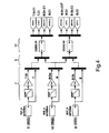
- Figure 4 is a block diagram of part of the detector 1 of Figure 1 which processes the signals detected by the antennas 3 of Figure 3 .
- the next stage 9 comprises two multiplexors, the first multiplexor combining the signals from the top antenna T and middle antenna M and the second multiplexor combining the signals from the middle antenna M and the bottom antenna B.
- Equation (9) comprises feeding the output from the middle antenna M into two delta-sigma CODECs 11.
- the ratio C1 / C2 is evaluated by comparing the output from the middle antenna M through both CODECs 11 which allows R to be calculated.
- R By accurately calibrating M.G M /B.G B and T.G T /B.G B and by calculating the ratio C1 / C2 by comparing the output from the middle antenna through both CODECs 11, R can be calculated.
- an electromagnetic signal radiated by a current carrying conductor 25 may be distorted by secondary coupling onto a nearby conductor.
- common mode field distortion which is homogenous
- field distortion due to coupling onto a nearby conductor leads to a non-radial field gradient and cannot be exactly compensated for.
- the common mode field distortion calculation resulting from comparison of the two antenna depth equation (3) and the three antenna depth equation (12) should give a common mode field distortion, C , of ⁇ 10% of the detected signal.
- the distortion due to secondary coupling is significant then this will affect the accuracy of some measurements and it is useful to warn the operator of significant secondary coupling distortion which results in the lessened integrity of readings made by the detector. If the common mode field distortion is calculated as ⁇ 10% of the detected signal then this is an indication of the presence of secondary distortion and the operator of the detector 1 can be warned by a visual or audible alarm.
- depth data is presented to an operator by pressing a 'calculate depth' button on the detector once the detector has been placed in the correct position.
- the correct position for calculating the depth is when the antennas are vertically above the conductor and the axes of the antennas are perpendicular to the axis of the buried conductor.
- the correct location is found by moving the detector from side to side across the conductor and rotating the detector about a vertical axis.
- a peak response is detected by a horizontal antenna having its axis perpendicular to the axis of the conductor and a null response is detected by a vertical antenna and a horizontal antenna having their axis parallel to the axis of the conductor.
- the optimum location for calculating the depth of a buried conductor can be considered as a depth calculation "sweet spot".
- the present invention addresses the difficulty of locating the sweet spot by presenting the result of the depth calculation only when predetermined criteria are satisfied.
- FIG 5 is a schematic representation of two antennas B, V at the bottom of the detector 1 of Figure 1 .
- the detector 1 is located at a horizontal displacement x from the buried conductor 25 which is at a depth d below ground level 23.
- the bottom two antennas B, V of the detector are placed in close proximity to each other at the foot of the detector 1, one antenna B being disposed horizontally as described above and the other antenna V behind disposed vertically (when the detector 1 is held vertical), orthogonal to the bottom antenna B.
- a line 27 joining the buried conductor to the bottom antennas B, V is inclined at an angle ⁇ to the vertical.
- Figure 6 is a schematic representation of a further two of the antennas M, M90 of the detector 1 of Figure 1 viewed from above showing the first middle horizontal antenna M and a second middle horizontal antenna M90.
- the middle two antennas M, M90 of the detector are placed in close proximity to each other in the middle of the detector 1, both antennas M, M90 being disposed horizontally (when the detector 1 is held vertical) at right angles to each other.
- the detector 1 is oriented relative to the buried conductor 25 such that the middle antennas M, M90 are horizontal and the angle between the axis of the conductor 25 and the second horizontal middle antenna M90, i.e., the angle between the axis of the conductor and a plane perpendicular to the axis of the middle antenna M, is ⁇ .
- the axis of the first middle antenna M should be oriented vertically above and orthogonal to the buried conductor 25.
- V By monitoring the current induced in the two middle antennas M, M90 and the two bottom antennas B, V the angles ⁇ and ⁇ can be calculated. These angle calculations can be used to determine if the detector 1 is located in the depth calculation sweet spot where a depth calculation can be accurately undertaken. If it is determined that the detector 1 is located in the sweet spot then the detector 1 displays the result of the depth calculation to the user on the display 21.
- Predetermined criteria indicating that the detector 1 is in the sweet spot are when the angles ⁇ and ⁇ are within ⁇ 10°, preferably within ⁇ 5° and preferably within ⁇ 2°.
- Further parameters can be considered to verify the integrity of the depth calculation. If the parameters satisfy predetermined criteria then the depth calculation will be displayed on the display 21 of the detector 1.
- One or more of the following parameters may be considered and preferably all of the following parameters are evaluated and should satisfy predetermined criteria. These parameters may be considered for depth calculation based on measurements using two or three horizontal antennas, i.e., using equations (3) or (12).
- Figure 7 is a block diagram of part of the digital signal processing block 13 of the detector 1 of Figure 1 .
- the field strength signals 5 from the antennas 3 are sampled in the CODEC 11 of Figure 1 and mixed with cos and sin components of the frequency of interest to produce in-phase "I” and quadrature "Q" components of the field strength signals detected at the antenna 3. Further details of this operation are provided in Radiodectection Limited's application published as GB 2400674 , the contents of which are incorporated herein by reference.
- the I and Q components are passed to a sinc 5 decimating filter 29. Further details of the operation of the sinc 5 decimating filter are provided in Radiodetection Limited's application published as GB 2400994 , the contents of which are incorporated herein by reference.
- the output of the sinc 5 decimating filter is down-sampled 31 and low-pass filtered through a finite impulse response (FIR) filter. This process results in obtaining the complex phase and magnitude of the antenna signals defined in a narrow bandwidth, typically 10 Hz. Further details of the operation of the DSP's tasks are provided in Radiodetection Limited's applications published as WO 03/071311 , WO 03/069598 and GB 2400674 , the contents of which are incorporated herein by reference.
- the magnitude of the second derivative of the phase of the signals detected by the antennas i.e. / d ⁇ t 2 d 2 ⁇ U is a parameter which can be considered to verify the integrity of the depth calculation.
- This parameter is effectively a measure of the uncorrelated noise across the bandwidth of the FIR filter and should be less than 0.5°/s 2 , preferably less than 0.2°/s 2 and preferably less than 0.1°/s 2 .
- a further parameter that can be considered to verify the integrity of the depth calculation is the standard deviation of the depth calculation. This parameter indicates that the depth calculation is stable and not unduly fluctuating due to noise.
- the standard deviation of the depth calculation referred to a 10 Hz bandwidth should be less than 5%, preferably less than 2% and preferably less than 1%.
- a further parameter which may be considered to verify the integrity of the depth calculation is that all signals input to the CODEC are within the dynamic range of the CODEC. If the signals input to the CODEC are found to be outside the dynamic range of the CODEC then this will result in inaccurate sampling by the CODEC.
- a further parameter which may be considered to verify the integrity of the depth calculation is the first derivative of the magnitude of the signals detected at the antennas, i.e., dU / dt .
- This parameter ensures that the instrument is being held still at the time that the depth is calculated so that this parameter acts as an anti-ballistic filter.
- the first derivative of the magnitude of the detected signal should be less than 5% of the signal/s, preferably less than 2% of the signal/s and preferably less than 1% of the signal/s.
- a further parameter which may be considered to verify the integrity of the depth calculation is the phase correlation across the (two or three) antennas used to detect the signal radiated by the buried conductor.
- the phase difference between the antennas should be less than 5°, preferably less than 2° and preferably less than 1°.
- One or more of the above parameters may be considered to determine that the depth calculation has good integrity.
- the values of the thresholds described above are dependent on the signal strength, the computing bandwidth of the FIR filters and the depth of the conductor being detected.
- the detector continuously calculates the depth of the buried conductor but only displays the calculated depth when predetermined criteria are satisfied.
- the detector may display an icon on its user interface or make an audible sound to inform the operator that the predetermined criteria are satisfied.
- the detector may be configured such that depth is only calculated when the predetermined criteria are satisfied.
- the processing apparatuses can comprise any suitably programmed apparatuses such as a general purpose computer, personal digital assistant, mobile telephone (such as a WAP or 3G-compliant phone) and so on. Since the present invention can be implemented as software, each and every aspect of the present invention thus encompasses computer software implementable on a programmable device.
- the computer software can be provided to the programmable device using any conventional carrier medium.
- the carrier medium can comprise a transient carrier medium such as an electrical, optical, microwave, acoustic or radio frequency signal carrying the computer code.
- transient medium is a TCP/IP signal carrying computer code over an IP network, such as the Internet.
- the carrier medium can also comprise a storage medium for storing processor readable code such as a floppy disk, hard disk, CD ROM, magnetic tape device or solid state memory device.
Landscapes
- Engineering & Computer Science (AREA)
- Remote Sensing (AREA)
- Physics & Mathematics (AREA)
- Life Sciences & Earth Sciences (AREA)
- Electromagnetism (AREA)
- General Physics & Mathematics (AREA)
- Environmental & Geological Engineering (AREA)
- Geology (AREA)
- General Life Sciences & Earth Sciences (AREA)
- Geophysics (AREA)
- Geophysics And Detection Of Objects (AREA)
Claims (12)
- Détecteur pour calculer la distorsion d'un champ électromagnétique produit par un conducteur enfoui (25) transportant un courant, le détecteur comprenant :une première antenne (B) ;une deuxième antenne (M) ayant son axe parallèle à un axe de la première antenne (B) et espacée d'une distance s de la première antenne (B) ;une troisième antenne (T) ayant son axe parallèle aux axes des première (B) et deuxième (M) antennes et espacée d'une distance 2s de la première antenne (B) et d'une distance s de la deuxième antenne (M) ;un moyen pour comparer les champs magnétiques au niveau des première (B) et deuxième (M) antennes pour produire une première valeur comparée ;un moyen pour comparer les champs magnétiques au niveau des première (B) et troisième (T) antennes pour produire une deuxième valeur comparée ;un premier moyen pour calculer la profondeur dudit conducteur enfoui (25) sur la base des première et deuxième valeurs comparées ;un deuxième moyen pour calculer la profondeur dudit conducteur enfoui (25) sur la base du champ magnétique au niveau d'une paire des première (B), deuxième (M) et troisième (T) antennes ; etun moyen pour comparer le calcul de profondeur du premier moyen pour calculer une profondeur et du deuxième moyen pour calculer une profondeur pour calculer la distorsion du champ électromagnétique produit par ledit conducteur enfoui (25) transportant un courant.
- Détecteur selon la revendication 1, dans lequel les champs magnétiques au niveau des première (B) et deuxième (M) antennes et les champs magnétiques au niveau des première (B) et troisième (T) antennes sont comparés en utilisant la relation :

où :BB est le champ électromagnétique au niveau de la première antenne (B),BM est le champ électromagnétique au niveau de la deuxième antenne (M), etBT est le champ électromagnétique au niveau de la troisième antenne (T) ; etle premier moyen pour calculer la profondeur est agencé pour calculer une première valeur de profondeur d1 dudit conducteur (25) au-dessous de la première antenne (B) en utilisant la relation :
et le deuxième moyen pour calculer la profondeur est agencé pour calculer une deuxième valeur de profondeur d2 dudit conducteur (25) au-dessous de la première antenne (B) en utilisant la relation:
- Détecteur selon la revendication 2, comprenant en outre un moyen pour alerter un opérateur (21) lorsque la distorsion du champ électromagnétique produit par ledit conducteur enfoui (25) transportant un courant est supérieure ou égale à 10 %.
- Détecteur selon la revendication 1, 2 ou 3, dans lequel chaque antenne (3, B, M, T) délivre un signal d'intensité de champ analogique représentatif du champ électromagnétique au niveau de l'antenne (3, B, M, T).
- Détecteur selon la revendication 4, comprenant en outre un moyen pour amplifier (7) les signaux d'intensité de champ.
- Détecteur selon la revendication 5, comprenant en outre :un moyen pour convertir (11) les signaux d'intensité de champ analogiques en signaux numériques ; etun moyen pour traiter (13) les signaux numériques pour isoler des signaux de bandes de fréquence prédéterminées.
- Détecteur selon la revendication 6, dans lequel le moyen pour convertir les signaux d'intensité de champ analogiques en signaux numériques est un codec stéréo delta-sigma (11).
- Détecteur selon l'une quelconque des revendications précédentes, dans lequel chaque paire des première (B) et deuxième (M) antennes et des première (B) et troisième (T) antennes est détalonnée avec une précision d'au moins 1 pour 600.000.
- Procédé de calcul de la distorsion d'un champ électromagnétique produit par un conducteur enfoui (25) transportant un courant, le procédé consistant à :comparer les champs magnétiques au niveau d'une première antenne (B) et au niveau d'une deuxième antenne (M) pour produire une première valeur comparée, ladite première antenne (B) ayant son axe parallèle à un axe de ladite deuxième antenne (M) et étant espacée d'une distance s de ladite deuxième antenne (M)comparer les champs magnétiques au niveau de ladite première antenne (B) et au niveau d'une troisième antenne (T) pour produire une deuxième valeur comparée, ladite troisième antenne (T) ayant son axe parallèle auxdits axes desdites première (B) et deuxième (M) antennes et étant espacée d'une distance 2s de ladite première antenne (B) et d'une distance s de ladite deuxième antenne (M),calculer une première valeur de profondeur dudit conducteur enfoui (25) sur la base des première et deuxième valeurs comparées ;calculer une deuxième valeur de profondeur dudit conducteur enfoui (25) sur la base du champ magnétique au niveau d'une paire des première (B), deuxième (M) et troisième (T) antennes ; etcomparer la première valeur de profondeur et la deuxième valeur de profondeur pour calculer la distorsion du champ électromagnétique produit par ledit conducteur enfoui (25) transportant un courant.
- Procédé selon la revendication 9, dans lequel les champs magnétiques au niveau desdites première (B) et deuxième (M) antennes et les champs magnétiques au niveau desdites première (B) et troisième (T) antennes sont comparées en utilisant la relation :

où :BB est le champ électromagnétique au niveau de ladite première antenne (B),BM est le champ électromagnétique au niveau de ladite deuxième antenne (M), etBT est le champ électromagnétique au niveau de ladite troisième antenne (T) ; etla première valeur de profondeur d1 dudit conducteur (25) au-dessous de ladite première antenne (B) est d'abord calculée en utilisant la relation :
et la deuxième valeur de profondeur d2 dudit conducteur (25) au-dessous de ladite première antenne (B) est ensuite calculée en utilisant la relation :
- Procédé selon la revendication 10, consistant en outre à alerter un opérateur lorsque la distorsion du champ électromagnétique produit par ledit conducteur enfoui (25) transportant un courant est supérieure ou égale à 10 %.
- Moyen de support supportant un code pouvant être lu par un ordinateur pour commander un microprocesseur (13) pour mettre en oeuvre le procédé selon l'une quelconque des revendications 9 à 11.
Applications Claiming Priority (1)
| Application Number | Priority Date | Filing Date | Title |
|---|---|---|---|
| GB0803990A GB2458119B (en) | 2008-03-03 | 2008-03-03 | A detector for calculating the distortion of an electromagnetic field produced by a buried current carrying conductor |
Publications (3)
| Publication Number | Publication Date |
|---|---|
| EP2098888A2 EP2098888A2 (fr) | 2009-09-09 |
| EP2098888A3 EP2098888A3 (fr) | 2011-03-23 |
| EP2098888B1 true EP2098888B1 (fr) | 2012-04-18 |
Family
ID=39315908
Family Applications (1)
| Application Number | Title | Priority Date | Filing Date |
|---|---|---|---|
| EP09250557A Not-in-force EP2098888B1 (fr) | 2008-03-03 | 2009-02-27 | Détecteur pour le calcul de la distorsion d'un champ électromagnétique produit par un conducteur enterré transportant du courant |
Country Status (6)
| Country | Link |
|---|---|
| US (1) | US8566043B2 (fr) |
| EP (1) | EP2098888B1 (fr) |
| CN (2) | CN101526628B (fr) |
| CA (1) | CA2656682A1 (fr) |
| ES (1) | ES2385861T3 (fr) |
| GB (1) | GB2458119B (fr) |
Families Citing this family (12)
| Publication number | Priority date | Publication date | Assignee | Title |
|---|---|---|---|---|
| GB2457954B (en) * | 2008-02-29 | 2012-04-04 | Radiodetection Ltd | A detector for detecting a current carrying conductor and a method of validating operations of the detector |
| GB2458121B (en) * | 2008-03-03 | 2012-01-25 | Radiodetection Ltd | A detector for calculating a depth of a buried conductor |
| GB2458119B (en) * | 2008-03-03 | 2010-12-29 | Radiodetection Ltd | A detector for calculating the distortion of an electromagnetic field produced by a buried current carrying conductor |
| US8742747B2 (en) * | 2010-12-06 | 2014-06-03 | Radiodetection Limited | Detector for detecting a current carrying conductor |
| DE102010063546A1 (de) | 2010-12-20 | 2012-06-21 | Robert Bosch Gmbh | Leitungssucher |
| US9285206B1 (en) * | 2012-02-07 | 2016-03-15 | Pile Dynamics, Inc. | Measurement device for pile displacement and method for use of the same |
| US9450684B2 (en) * | 2012-02-08 | 2016-09-20 | Vital Alert Communication Inc. | System, method and apparatus for controlling buried devices |
| US9488747B2 (en) * | 2012-03-23 | 2016-11-08 | Seesoon, Inc. | Gradient antenna coils and arrays for use in locating systems |
| US9194978B2 (en) * | 2013-05-13 | 2015-11-24 | Radiodetection Ltd. | Electronic marker locator systems and methods |
| CN103278859B (zh) * | 2013-06-07 | 2015-12-09 | 国家电网公司 | 基于地下电缆综合检测系统的信号接收处理系统 |
| US10094947B2 (en) * | 2015-10-07 | 2018-10-09 | Metrotech Corporation | System and method for locating underground lines using antenna and positioning information |
| US9857494B2 (en) | 2015-12-01 | 2018-01-02 | Mclaughlin Group, Inc. | System and method for locating an underground utility |
Family Cites Families (21)
| Publication number | Priority date | Publication date | Assignee | Title |
|---|---|---|---|---|
| JPS499388B1 (fr) * | 1968-05-25 | 1974-03-04 | ||
| US4639674A (en) * | 1983-04-11 | 1987-01-27 | Schonstedt Instrument Company | Apparatus and method employing extraneous field compensation for locating current-carrying objects |
| JPS6193973A (ja) | 1984-10-15 | 1986-05-12 | Hitachi Ltd | 地中埋設管の位置検出方法 |
| JPS6266184A (ja) * | 1985-09-18 | 1987-03-25 | Fuji Tekomu Kk | 埋設鉄管等の深度測定装置 |
| JPS62254089A (ja) | 1986-04-25 | 1987-11-05 | Tokyo Gas Co Ltd | 磁場を測定して直線状埋設物の位置を検知する場合の精度判定方法 |
| JP2865599B2 (ja) | 1995-10-09 | 1999-03-08 | 株式会社横井製作所 | 埋設物の探査方法 |
| US6204667B1 (en) * | 1998-03-18 | 2001-03-20 | Geophex, Ltd. | Electromagnetic gradiometer having a primary detector and a plurality of secondary detectors |
| US6356082B1 (en) * | 2000-05-26 | 2002-03-12 | Schonstedt Instruments Co. | Utility locator radio link |
| US7184951B2 (en) | 2002-02-15 | 2007-02-27 | Radiodetection Limted | Methods and systems for generating phase-derivative sound |
| WO2003071311A1 (fr) | 2002-02-19 | 2003-08-28 | Radiodetection Limited | Systeme et procede permettant de detecter un conducteur de courant dissimule |
| US6815953B1 (en) * | 2002-07-03 | 2004-11-09 | Metrotech Corporation | Detecting field distortion in underground line location |
| US7088105B2 (en) * | 2002-10-02 | 2006-08-08 | Mclaughlin Manufacturing Company, Inc. | System and method for locating underground utilities carrying passive signals |
| US6977508B2 (en) | 2003-03-31 | 2005-12-20 | Radiodetection Limited | Cable detection apparatus and method |
| US7120564B2 (en) * | 2003-04-03 | 2006-10-10 | Metrotech Corporation | Buried line locator with integral position sensing |
| US6968296B2 (en) | 2003-04-04 | 2005-11-22 | Radiodetection Limited | Cable detector with decimating filter and filtering method |
| US7285958B2 (en) * | 2004-01-15 | 2007-10-23 | Metrotech Corporation, Inc. | Method and apparatus for digital detection of electronic markers using frequency adaptation |
| US7356421B2 (en) * | 2004-07-29 | 2008-04-08 | Metrotech Corporation, Inc. | Precise location of buried metallic pipes and cables in the presence of signal distortion |
| US7571263B2 (en) * | 2004-12-02 | 2009-08-04 | Hitachi Global Storage Technologies Netherlands B.V. | Apparatus and method for monitoring data storage device for usage and warranty |
| GB2427475B (en) * | 2005-06-20 | 2008-07-09 | Radiodetection Ltd | A detector for detecting a buried current carrying conductor |
| US8209136B2 (en) * | 2007-05-18 | 2012-06-26 | Metrotech Corporation, Inc. | Enhanced precise location |
| GB2458119B (en) | 2008-03-03 | 2010-12-29 | Radiodetection Ltd | A detector for calculating the distortion of an electromagnetic field produced by a buried current carrying conductor |
-
2008
- 2008-03-03 GB GB0803990A patent/GB2458119B/en not_active Expired - Fee Related
-
2009
- 2009-02-27 EP EP09250557A patent/EP2098888B1/fr not_active Not-in-force
- 2009-02-27 ES ES09250557T patent/ES2385861T3/es active Active
- 2009-03-02 CN CN2009101184181A patent/CN101526628B/zh active Active
- 2009-03-02 US US12/396,413 patent/US8566043B2/en not_active Expired - Fee Related
- 2009-03-02 CN CN2009200075676U patent/CN201749197U/zh not_active Expired - Lifetime
- 2009-03-02 CA CA002656682A patent/CA2656682A1/fr not_active Abandoned
Also Published As
| Publication number | Publication date |
|---|---|
| EP2098888A2 (fr) | 2009-09-09 |
| CN201749197U (zh) | 2011-02-16 |
| CN101526628B (zh) | 2012-08-29 |
| GB0803990D0 (en) | 2008-04-09 |
| ES2385861T3 (es) | 2012-08-01 |
| CA2656682A1 (fr) | 2009-09-03 |
| GB2458119B (en) | 2010-12-29 |
| GB2458119A (en) | 2009-09-09 |
| EP2098888A3 (fr) | 2011-03-23 |
| CN101526628A (zh) | 2009-09-09 |
| US20100004880A1 (en) | 2010-01-07 |
| US8566043B2 (en) | 2013-10-22 |
Similar Documents
| Publication | Publication Date | Title |
|---|---|---|
| EP2098888B1 (fr) | Détecteur pour le calcul de la distorsion d'un champ électromagnétique produit par un conducteur enterré transportant du courant | |
| EP2098890B1 (fr) | Détecteur pour le calcul de la profondeur de conducteur enterré | |
| US8183851B2 (en) | Detector for calculating a depth of a buried conductor | |
| CN101248372B (zh) | 判断埋地载流导体是否埋在预定最小深度之上的方法及设备 | |
| US6407550B1 (en) | Line locator with accurate horizontal displacement detection | |
| CN101365966B (zh) | 探测载流导体的方法及设备 | |
| CN101243334B (zh) | 探测埋地载流导体的探测器 | |
| JPH04340491A (ja) | 埋設物探査装置 | |
| CN101365954B (zh) | 用于探测埋地载流导体的探测器的无线电模式选择模块 | |
| CN101243333A (zh) | 探测埋地载流导体的探测器 | |
| US8742747B2 (en) | Detector for detecting a current carrying conductor | |
| US8676522B2 (en) | Detector for detecting a current carrying conductor | |
| Manstein et al. | A device for shallow frequency-domain electromagnetic induction sounding | |
| GB2486218A (en) | Detecting the position/orientation of an underground pipe from the in-phase component of a signal measured by a magnetic field detector | |
| GB2486219A (en) | A detector for detecting a buried conductor comprising at least two magnetic field detectors | |
| KR101517760B1 (ko) | 자기마커 위치 탐지를 위한 캘리브레이션 장치 및 방법 | |
| EP2589988B1 (fr) | Dispositif de localisation permettant de localiser un conducteur porteur de courant | |
| JPH07234284A (ja) | 位相制御による電磁探査の信号処理方法と位相制御 による電磁探査の信号処理装置 | |
| JPH08502129A (ja) | サーキットトレーサ |
Legal Events
| Date | Code | Title | Description |
|---|---|---|---|
| PUAI | Public reference made under article 153(3) epc to a published international application that has entered the european phase |
Free format text: ORIGINAL CODE: 0009012 |
|
| AK | Designated contracting states |
Kind code of ref document: A2 Designated state(s): AT BE BG CH CY CZ DE DK EE ES FI FR GB GR HR HU IE IS IT LI LT LU LV MC MK MT NL NO PL PT RO SE SI SK TR |
|
| AX | Request for extension of the european patent |
Extension state: AL BA RS |
|
| PUAL | Search report despatched |
Free format text: ORIGINAL CODE: 0009013 |
|
| AK | Designated contracting states |
Kind code of ref document: A3 Designated state(s): AT BE BG CH CY CZ DE DK EE ES FI FR GB GR HR HU IE IS IT LI LT LU LV MC MK MT NL NO PL PT RO SE SI SK TR |
|
| AX | Request for extension of the european patent |
Extension state: AL BA RS |
|
| 17P | Request for examination filed |
Effective date: 20110721 |
|
| GRAP | Despatch of communication of intention to grant a patent |
Free format text: ORIGINAL CODE: EPIDOSNIGR1 |
|
| AKX | Designation fees paid |
Designated state(s): DE ES FR IT |
|
| GRAS | Grant fee paid |
Free format text: ORIGINAL CODE: EPIDOSNIGR3 |
|
| GRAA | (expected) grant |
Free format text: ORIGINAL CODE: 0009210 |
|
| AK | Designated contracting states |
Kind code of ref document: B1 Designated state(s): DE ES FR IT |
|
| REG | Reference to a national code |
Ref country code: DE Ref legal event code: R096 Ref document number: 602009006422 Country of ref document: DE Effective date: 20120614 |
|
| REG | Reference to a national code |
Ref country code: ES Ref legal event code: FG2A Ref document number: 2385861 Country of ref document: ES Kind code of ref document: T3 Effective date: 20120801 |
|
| PLBE | No opposition filed within time limit |
Free format text: ORIGINAL CODE: 0009261 |
|
| STAA | Information on the status of an ep patent application or granted ep patent |
Free format text: STATUS: NO OPPOSITION FILED WITHIN TIME LIMIT |
|
| 26N | No opposition filed |
Effective date: 20130121 |
|
| REG | Reference to a national code |
Ref country code: DE Ref legal event code: R097 Ref document number: 602009006422 Country of ref document: DE Effective date: 20130121 |
|
| REG | Reference to a national code |
Ref country code: FR Ref legal event code: PLFP Year of fee payment: 8 |
|
| REG | Reference to a national code |
Ref country code: FR Ref legal event code: PLFP Year of fee payment: 9 |
|
| REG | Reference to a national code |
Ref country code: FR Ref legal event code: PLFP Year of fee payment: 10 |
|
| PGFP | Annual fee paid to national office [announced via postgrant information from national office to epo] |
Ref country code: DE Payment date: 20240902 Year of fee payment: 16 |
|
| PGFP | Annual fee paid to national office [announced via postgrant information from national office to epo] |
Ref country code: FR Payment date: 20240805 Year of fee payment: 16 |
|
| PGFP | Annual fee paid to national office [announced via postgrant information from national office to epo] |
Ref country code: ES Payment date: 20240902 Year of fee payment: 16 |
|
| PGFP | Annual fee paid to national office [announced via postgrant information from national office to epo] |
Ref country code: IT Payment date: 20240820 Year of fee payment: 16 |
|
| REG | Reference to a national code |
Ref country code: DE Ref legal event code: R119 Ref document number: 602009006422 Country of ref document: DE |
|
| PG25 | Lapsed in a contracting state [announced via postgrant information from national office to epo] |
Ref country code: DE Free format text: LAPSE BECAUSE OF NON-PAYMENT OF DUE FEES Effective date: 20250902 |
|
| PG25 | Lapsed in a contracting state [announced via postgrant information from national office to epo] |
Ref country code: FR Free format text: LAPSE BECAUSE OF NON-PAYMENT OF DUE FEES Effective date: 20250228 Ref country code: IT Free format text: LAPSE BECAUSE OF NON-PAYMENT OF DUE FEES Effective date: 20250227 |
|
| REG | Reference to a national code |
Ref country code: ES Ref legal event code: FD2A Effective date: 20260407 |
|
| PG25 | Lapsed in a contracting state [announced via postgrant information from national office to epo] |
Ref country code: ES Free format text: LAPSE BECAUSE OF NON-PAYMENT OF DUE FEES Effective date: 20250228 |