EP2098890B1 - Detektor zur Berechnung der Tiefe eines verborgenen Leiters - Google Patents
Detektor zur Berechnung der Tiefe eines verborgenen Leiters Download PDFInfo
- Publication number
- EP2098890B1 EP2098890B1 EP09250574.2A EP09250574A EP2098890B1 EP 2098890 B1 EP2098890 B1 EP 2098890B1 EP 09250574 A EP09250574 A EP 09250574A EP 2098890 B1 EP2098890 B1 EP 2098890B1
- Authority
- EP
- European Patent Office
- Prior art keywords
- antennas
- detector
- conductor
- calculating
- depth
- Prior art date
- Legal status (The legal status is an assumption and is not a legal conclusion. Google has not performed a legal analysis and makes no representation as to the accuracy of the status listed.)
- Not-in-force
Links
Images


Classifications
-
- G—PHYSICS
- G01—MEASURING; TESTING
- G01R—MEASURING ELECTRIC VARIABLES; MEASURING MAGNETIC VARIABLES
- G01R29/00—Arrangements for measuring or indicating electric quantities not covered by groups G01R19/00 - G01R27/00
- G01R29/08—Measuring electromagnetic field characteristics
- G01R29/0807—Measuring electromagnetic field characteristics characterised by the application
- G01R29/0814—Field measurements related to measuring influence on or from apparatus, components or humans, e.g. in ESD, EMI, EMC, EMP testing, measuring radiation leakage; detecting presence of micro- or radiowave emitters; dosimetry; testing shielding; measurements related to lightning
- G01R29/085—Field measurements related to measuring influence on or from apparatus, components or humans, e.g. in ESD, EMI, EMC, EMP testing, measuring radiation leakage; detecting presence of micro- or radiowave emitters; dosimetry; testing shielding; measurements related to lightning for detecting presence or location of electric lines or cables
-
- G—PHYSICS
- G01—MEASURING; TESTING
- G01V—GEOPHYSICS; GRAVITATIONAL MEASUREMENTS; DETECTING MASSES OR OBJECTS; TAGS
- G01V3/00—Electric or magnetic prospecting or detecting; Measuring magnetic field characteristics of the earth, e.g. declination, deviation
- G01V3/08—Electric or magnetic prospecting or detecting; Measuring magnetic field characteristics of the earth, e.g. declination, deviation operating with magnetic or electric fields produced or modified by objects or geological structures or by detecting devices
- G01V3/10—Electric or magnetic prospecting or detecting; Measuring magnetic field characteristics of the earth, e.g. declination, deviation operating with magnetic or electric fields produced or modified by objects or geological structures or by detecting devices using induction coils
Definitions
- the present invention relates to a detector for calculating the depth of a buried conductor.
- One type of such detector works in one of two modes, namely 'active' or 'passive' modes. Each mode has its own frequency bands of detection.
- the passive mode comprises 'power' mode and 'radio' mode.
- the detector detects the magnetic field produced by a conductor carrying an AC mains power supply at 50/60 Hz, or the magnetic field re-radiated from a conductor as a result of a nearby cable carrying AC power, together with higher harmonics up to about 5KHz.
- the detector detects very low frequency (VLF) radio energy which is re-radiated by buried conductors.
- VLF very low frequency
- the source of the original VLF radio signals is a plurality of VLF long wave transmitters, both commercial and military.
- a signal transmitter In the active mode, a signal transmitter produces an alternating magnetic field of known frequency and modulation, which induces a current in a nearby buried conductor.
- the signal transmitter may be directly connected to the conductor or, where direct connection access is not possible, a signal transmitter may be placed near to the buried conductor and a signal may be induced in the conductor. The buried conductor re-radiates the signal produced by the signal transmitter.
- US4220913 describes apparatus for and methods of electromagnetic surveying of elongated underground conductors.
- US5920194 describes a device for locating objects that emit electromagnetic signals.
- This invention provides further advancements to existing systems for calculating the depth of buried current carrying conductors, providing additional functionality and benefits to the user.
- a detector for calculating a depth of a buried conductor comprising: a plurality of antennas for detecting an electromagnetic field radiated by said conductor; means for calculating the depth of said conductor based on the field detected by the antennas; and means for displaying the calculated depth of said conductor, wherein the detector is configured to operate such that the calculated depth is displayed only when one or more predetermined criteria are satisfied wherein the detector comprises means for calculating an angle ⁇ between the vertical and a line joining said conductor to the detector, wherein a predetermined criterion is the angle ⁇ is within ⁇ 10°, and / or means for calculating an angle ⁇ between an axis of said conductor and a plane perpendicular to an axis of the antennas, wherein a predetermined criterion is the angle ⁇ is within ⁇ 10°.
- the detector may further comprise means for calculating the second derivative of the phase of the electromagnetic fields detected at the antennas, wherein a predetermined criterion is the second derivative of the phase is less than 0.5°/s 2 , preferably less than 0.2°/s 2 and preferably less than 0.1°/s 2 .
- the detector may further comprise means for calculating the standard deviation of the depth calculation referred to a 10 Hz bandwidth, wherein a predetermined criterion is the standard deviation of the depth calculation should be less than 5% of the calculated depth, preferably less than 2% and preferably less than 1 %.
- the detector may further comprise an analogue to digital converter, ADC, having a dynamic range for digitising signals output from the antennas, wherein a predetermined criterion is the signals input to the ADC are within the dynamic range of the ADC.
- ADC an analogue to digital converter
- the detector may further comprise means for calculating a first derivative with respect to time of a magnitude of the field detected at the antennas, wherein a predetermined criterion is the first derivative of the magnitude of the field detected at the antennas is less than 5% of the signal/s, preferably less than 2% of the signal/s and preferably less than 1% of the signal/s.
- the detector may further comprise means for calculating phase correlation across the antennas, wherein a predetermined criterion is the phase difference between the antennas is less than 5°, preferably less than 2° and preferably less than 1°.
- a method of calculating a depth of a buried conductor comprising: providing a plurality of antennas for detecting an electromagnetic field radiated by said conductor; calculating the depth of said conductor based on the field detected by the antennas; and providing a display device for displaying the calculated depth of said conductor, wherein the calculated depth is displayed on the display device only when one or more predetermined criteria are satisfied, wherein the method further comprises calculating an angle ⁇ between the vertical and a line joining said conductor to the detector, wherein a predetermined criterion is the angle ⁇ is within ⁇ 10°, and /or calculating an angle ⁇ between an axis of said conductor and a plane perpendicular to an axis of the antennas, wherein a predetermined criterion is the angle ⁇ is within ⁇ 10°.
- the method may further comprise calculating the second derivative of the phase of the electromagnetic fields detected at the antennas, wherein a predetermined criterion is the second derivative of the phase is less than 0.5°/s 2 , preferably less than 0.2°/s 2 and preferably less than 0.1/s 2 .
- the method may further comprise calculating the standard deviation of the depth calculation referred to a 10 Hz bandwidth, wherein a predetermined criterion is the standard deviation of the depth calculation should be less than 5%, preferably less than 2% and preferably less than 1%.
- the method may further comprise providing an analogue to digital converter, ADC, having a dynamic range for digitising signals output from the antennas, wherein a predetermined criterion is the signals input to the ADC are within the dynamic range of the ADC.
- ADC an analogue to digital converter
- the method may further comprise calculating a first derivative with respect to time of a magnitude of the field detected at the antennas, wherein a predetermined criterion is the first derivative of the magnitude of the field detected at the antennas is less than 5% of the signal/s, preferably less than 2% of the signal/s and preferably less than 1% of the signal/s.
- the method may further comprise calculating phase correlation across the antennas, wherein a predetermined criterion is the phase difference between the antennas is less than 5°, preferably less than 2° and preferably less than 1°.
- FIG. 1 is a block diagram of a portable detector 1 according to an embodiment of the invention.
- the detector 1 comprises five antennas 3 for detecting an electromagnetic signal radiated by a current carrying conductor.
- Each antenna 3 converts the electromagnetic field at the antenna into a field strength signal 5 which is output from the antenna 3.
- Each antenna output is passed to a pre-amplification and switching stage 7. If the strength of the field strength signal 5 is low then the output from the antenna 3 is amplified and filtered with an equalization filter. If the field strength signal 5 output from the antenna 3 is adequate then the signal is fed directly into the next stage of the detector 1. In addition to the outputs from the antennas 3, other inputs can be directly applied to the detector 1 for example from accessories such as clamps, stethoscopes, underwater-probes and an A-frame for fault finding.
- the output from the pre-amplification and switching stage 7 is fed into a superheterodyne mixer 9.
- the mixer circuit is designed to recover full magnitude and phase information from the carrier.
- the output from the mixers 9 are fed into a CODEC 11.
- the CODEC 11 is a 24-bit stereo delta-sigma analogue to digital converter (ADC). This is a relatively cheap device and has a poor absolute accuracy of ⁇ 1% but excellent ratiometric accuracy. However, the way that the CODEC 11 is used in the present invention makes it an ideal ADC as described below.
- the CODEC 11 over-samples the field strength signals at up to 96 KHz.
- the output of the CODEC 11 is fed into a digital signal processing block 13 which is comprised of a digital signal processor (DSP) and a field programmable date array (FPGA).
- DSP digital signal processor
- FPGA field programmable date array
- the detector 1 further comprises a power supply unit (PSU) 15 comprising a power source such as batteries and power management circuitry.
- a communications module 17 is provided to allow the detector 1 to be connected to a personal computer (PC) or personal digital assistant (PDA) to upload data stored in the detector 1 and to allow download from the PC/PDA to the detector 1, for example software updates.
- the detector 1 further comprises a memory module 19 and a user interface module 21.
- the user interface module 21 may comprise one or more of a display for displaying information to the operator of the device, input devices such as a keypad or a touch sensitive screen and audible output devices such as a speaker or beeper.
- the components of the portable detector 1 are housed in a housing (not shown).
- FIG. 2 is a schematic representation of two horizontal vertically spaced antennas B, T of a known detector within an elongate vertically held housing (not shown).
- the detector In use the detector is held vertical on ground 23 in which a current carrying conductor 25 is buried with the bottom antenna B close to the surface of the ground 23.
- the axes of the antennas are parallel and the separation between the bottom antenna B and the top antenna T is 2s .
- the conductor 25 is buried at a depth d below the surface of the ground 23 (and below the bottom antenna B) and the horizontal displacement between the antennas B and T and the conductor 25 is x.
- ⁇ 0 the permeability of free space
- i the current flowing in the conductor 25
- C is a frequency dependent variable, known as the common mode field distortion.
- Common mode field distortion is distortion of the electromagnetic field produced by the buried current carrying conductor 25 due to the complex impedance of the material in which the current carrying conductor 25 is buried.
- the common mode field distortion results is a homogenous distortion of the signal due to return current through the ground.
- the complex impedance of the ground varies for different materials such as dry soil, wet clay and sand. For example, at a frequency of 83KHz when the conductor is buried at a depth of 1.7m in wet clay the contribution of C gives a 34% variation to the theoretical value of B .
- the depth calculation using two antennas is dependent on the common mode field distortion which leads to practical difficulties in determining the depth of a buried conductor.
- This difficulty is mitigated in conventional apparatus by deploying a compensation algorithm which approximates the common mode field distortion based on measurements from different sites to give a function C for an 'average' soil type.
- This approximation is not satisfactory due to the significant difference in measurements of up to 35% between wet clay and dry sand, which in general leads to an underestimate of the depth of a buried current carrying conductor.
- FIG. 3 is a schematic representation of three horizontal vertically spaced antennas T, M, B of the detector 1 of Figure 1 .
- the axes of the antennas are parallel.
- the middle antenna M is disposed midway between the bottom antenna B and top antenna T at a separation s from each antenna so that the separation between the bottom antenna B and the top antenna T is 2s .
- the conductor 25 is buried at a depth d below the surface of the ground 23 (and below the bottom antenna B) and the horizontal displacement between the antennas T, M, B and the conductor is x.
- the ratio R is in effect a second derivative gradient term and is independent of the common mode distortion C .
- equations (9) and (12) provide a means of calculating the depth of a current carrying conductor 25 by comparing the magnetic field densities at the three antennas.
- equations (9) and (12) dispense with the need to compensate for the common mode field effect of the substance in which the current carrying conductor 25 is buried and these equations provide an improved method of calculating the depth of a buried conductor.
- Equations (1), (2) and (5) apply to an infinite conductor carrying uniform current and giving a perfect radial field in a vacuum. When such a conductor is buried in soil with finite conductivity a secondary current and magnetic field are generated which is induced in the soil.
- equation (13) is substituted into equation (9) for each of the antennas it can be shown that the exponential terms cancel and that common mode field effect is eliminated in the ratiometric analysis.
- a prerequisite of this ratiometric calculation is accurate calibration of the three horizontal antennas T, M, B to an accuracy of around 1 part in 600,000.
- the calibration of the antennas is performed with respect to the relative performance of the top and middle antennas T, M and the relative performance of the middle and bottom antennas M, B.
- each antenna is in turn placed within a known magnetic field and the magnitude and phase of the field strength signal output from the antennas is measured over a range of frequencies.
- a calibration value for the performance ratio of the top and middle antennas and the middle and bottom antennas is calculated and stored in the memory 19 of the detector 1 so that a ratiometric calculation of the field strength signals output from the pairs of antennas is consistently accurate to around 1 part in 600,000.
- Figure 4 is a block diagram of part of the detector 1 of Figure 1 which processes the signals detected by the antennas 3 of Figure 3 .
- the next stage 9 comprises two multiplexors, the first multiplexor combining the signals from the top antenna T and middle antenna M and the second multiplexor combining the signals from the middle antenna M and the bottom antenna B.
- Equation (9) comprises feeding the output from the middle antenna M into two delta-sigma CODECs 11.
- the ratio C1 / C2 is evaluated by comparing the output from the middle antenna M through both CODECs 11 which allows R to be calculated.
- R By accurately calibrating M.G M B.G B and T.G T /B.G B and by calculating the ratio C1 / C2 by comparing the output from the middle antenna through both CODECs 11, R can be calculated.
- an electromagnetic signal radiated by a current carrying conductor 25 may be distorted by secondary coupling onto a nearby conductor.
- common mode field distortion which is homogenous
- field distortion due to coupling onto a nearby conductor leads to a non-radial field gradient and cannot be exactly compensated for.
- the common mode field distortion calculation resulting from comparison of the two antenna depth equation (3) and the three antenna depth equation (12) should give a common mode field distortion, C , of ⁇ 10% of the detected signal.
- the distortion due to secondary coupling is significant then this will affect the accuracy of some measurements and it is useful to warn the operator of significant secondary coupling distortion which results in the lessened integrity of readings made by the detector. If the common mode field distortion is calculated as ⁇ 10% of the detected signal then this is an indication of the presence of secondary distortion and the operator of the detector 1 can be warned by a visual or audible alarm.
- depth data is presented to an operator by pressing a 'calculate depth' button on the detector once the detector has been placed in the correct position.
- the correct position for calculating the depth is when the antennas are vertically above the conductor and the axes of the antennas are perpendicular to the axis of the buried conductor.
- the correct location is found by moving the detector from side to side across the conductor and rotating the detector about a vertical axis.
- a peak response is detected by a horizontal antenna having its axis perpendicular to the axis of the conductor and a null response is detected by a vertical antenna and a horizontal antenna having their axis parallel to the axis of the conductor.
- the optimum location for calculating the depth of a buried conductor can be considered as a depth calculation "sweet spot".
- the present invention addresses the difficulty of locating the sweet spot by presenting the result of the depth calculation only when predetermined criteria are satisfied.
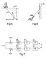
- FIG 5 is a schematic representation of two antennas B, V at the bottom of the detector 1 of Figure 1 .
- the detector 1 is located at a horizontal displacement x from the buried conductor 25 which is at a depth d below ground level 23.
- the bottom two antennas B, V of the detector are placed in close proximity to each other at the foot of the detector 1, one antenna B being disposed horizontally as described above and the other antenna V behind disposed vertically (when the detector 1 is held vertical), orthogonal to the bottom antenna B.
- a line 27 joining the buried conductor to the bottom antennas B, V is inclined at an angle ⁇ to the vertical.
- Figure 6 is a schematic representation of a further two of the antennas M, M90 of the detector 1 of Figure 1 viewed from above showing the first middle horizontal antenna M and a second middle horizontal antenna M90.
- the middle two antennas M, M90 of the detector are placed in close proximity to each other in the middle of the detector 1, both antennas M, M90 being disposed horizontally (when the detector 1 is held vertical) at right angles to each other.
- the detector 1 is oriented relative to the buried conductor 25 such that the middle antennas M, M90 are horizontal and the angle between the axis of the conductor 25 and the second horizontal middle antenna M90, i.e., the angle between the axis of the conductor and a plane perpendicular to the axis of the middle antenna M, is ⁇ .
- the axis of the first middle antenna M should be oriented vertically above and orthogonal to the buried conductor 25.
- V By monitoring the current induced in the two middle antennas M, M90 and the two bottom antennas B, V the angles ⁇ and ⁇ can be calculated. These angle calculations can be used to determine if the detector 1 is located in the depth calculation sweet spot where a depth calculation can be accurately undertaken. If it is determined that the detector 1 is located in the sweet spot then the detector 1 displays the result of the depth calculation to the user on the display 21.
- Predetermined criteria indicating that the detector 1 is in the sweet spot are when the angles ⁇ and ⁇ are within ⁇ 10°, preferably within ⁇ 5° and preferably within ⁇ 2°.
- Further parameters can be considered to verify the integrity of the depth calculation. If the parameters satisfy predetermined criteria then the depth calculation will be displayed on the display 21 of the detector 1.
- One or more of the following parameters may be considered and preferably all of the following parameters are evaluated and should satisfy predetermined criteria. These parameters may be considered for depth calculation based on measurements using two or three horizontal antennas, i.e., using equations (3) or (12).
- Figure 7 is a block diagram of part of the digital signal processing block 13 of the detector 1 of Figure 1 .
- the field strength signals 5 from the antennas 3 are sampled in the CODEC 11 of Figure 1 and mixed with cos and sin components of the frequency of interest to produce in-phase "I” and quadrature "Q" components of the field strength signals detected at the antenna 3. Further details of this operation are provided in Radiodectection Limited's application published as GB 2400674 , the contents of which are incorporated herein by reference.
- the I and Q components are passed to a sinc 5 decimating filter 29. Further details of the operation of the sinc 5 decimating filter are provided in Radiodetection Limited's application published as GB 2400994 , the contents of which are incorporated herein by reference.
- the output of the sinc 5 decimating filter is down-sampled 31 and low-pass filtered through a finite impulse response (FIR) filter. This process results in obtaining the complex phase and magnitude of the antenna signals defined in a narrow bandwidth, typically 10 Hz. Further details of the operation of the DSP's tasks are provided in Radiodetection Limited's applications published as WO 03/071311 , WO 03/069598 and GB 2400674 .
- the magnitude of the second derivative of the phase of the signals detected by the antennas i.e. d 2 ⁇ / dt 2 U is a parameter which can be considered to verify the integrity of the depth calculation.
- This parameter is effectively a measure of the uncorrelated noise across the bandwidth of the FIR filter and should be less than 0.5°/s 2 , preferably less than 0.2°/s 2 and preferably less than 0.1°/s 2 .
- a further parameter that can be considered to verify the integrity of the depth calculation is the standard deviation of the depth calculation. This parameter indicates that the depth calculation is stable and not unduly fluctuating due to noise.
- the standard deviation of the depth calculation referred to a 10 Hz bandwidth should be less than 5%, preferably less than 2% and preferably less than 1%.
- a further parameter which may be considered to verify the integrity of the depth calculation is that all signals input to the CODEC are within the dynamic range of the CODEC. If the signals input to the CODEC are found to be outside the dynamic range of the CODEC then this will result in inaccurate sampling by the CODEC.
- a further parameter which may be considered to verify the integrity of the depth calculation is the first derivative of the magnitude of the signals detected at the antennas, i.e., dU / dt .
- This parameter ensures that the instrument is being held still at the time that the depth is calculated so that this parameter acts as an anti-ballistic filter.
- the first derivative of the magnitude of the detected signal should be less than 5% of the signal/s, preferably less than 2% of the signal/s and preferably less than 1% of the signal/s.
- a further parameter which may be considered to verify the integrity of the depth calculation is the phase correlation across the (two or three) antennas used to detect the signal radiated by the buried conductor.
- the phase difference between the antennas should be less than 5°, preferably less than 2° and preferably less than 1°.
- One or more of the above parameters may be considered to determine that the depth calculation has good integrity.
- the values of the thresholds described above are dependent on the signal strength, the computing bandwidth of the FIR filters and the depth of the conductor being detected.
- the detector continuously calculates the depth of the buried conductor but only displays the calculated depth when predetermined criteria are satisfied.
- the detector may display an icon on its user interface or make an audible sound to inform the operator that the predetermined criteria are satisfied.
- the detector may be configured such that depth is only calculated when the predetermined criteria are satisfied.
Landscapes
- Physics & Mathematics (AREA)
- Engineering & Computer Science (AREA)
- Remote Sensing (AREA)
- Life Sciences & Earth Sciences (AREA)
- Electromagnetism (AREA)
- General Physics & Mathematics (AREA)
- Environmental & Geological Engineering (AREA)
- Geology (AREA)
- General Life Sciences & Earth Sciences (AREA)
- Geophysics (AREA)
- Geophysics And Detection Of Objects (AREA)
- Radar Systems Or Details Thereof (AREA)
Claims (12)
- Detektor zum Berechnen einer Tiefe eines vergrabenen Leiters (25), wobei der Detektor umfasst:eine Mehrzahl von Antennen (3) zum Detektieren eines elektromagnetischen Feldes, das durch den Leiter abgestrahlt wird;Mittel (13) zum Berechnen der Tiefe des Leiters basierend auf dem durch die Antennen detektierten Feld; undMittel (21) zum Anzeigen der berechneten Tiefe des Leiters,wobei der Detektor ausgebildet ist, so zu arbeiten, dass die berechnete Tiefe auf den Mitteln zum Anzeigen der berechneten Tiefe nur angezeigt wird, wenn ein oder mehrere vorbestimmte Kriterien erfüllt sind,dadurch gekennzeichnet, dass der Detektor des Weiteren umfasst:Mittel zum Berechnen eines Winkels θ zwischen der Vertikalen und einer Linie, die den Leiter mit dem Detektor verbindet, wobei ein vorbestimmtes Kriterium ist, dass der Winkel θ innerhalb von ±10° liegt, und/oderMittel zum Berechnen eines Winkels φ zwischen einer Achse des Leiters und einer Ebene senkrecht zu einer Achse der Antennen, wobei ein vorbestimmtes Kriterium ist, dass der Winkel φ innerhalb von ±10° liegt.
- Detektor nach Anspruch 1, des Weiteren umfassend Mittel zum Berechnen der zweiten Ableitung der Phase des an den Antennen detektierten elektromagnetischen Feldes, wobei ein vorbestimmtes Kriterium ist, dass die zweite Ableitung der Phase kleiner als 0.5°/s2 ist.
- Detektor nach einem der vorangegangenen Ansprüche, des Weiteren umfassend Mittel zum Berechnen der Standardabweichung der Tiefenberechnung in Bezug auf eine 10 Hz Bandbreite, wobei ein vorbestimmtes Kriterium ist, dass die Standardabweichung der Tiefenberechnung weniger als 5% der berechneten Tiefe betragen sollte.
- Detektor nach einem der vorangegangenen Ansprüche, des Weiteren umfassend einen Analog-zu-Digital-Wandler (11), der einen Dynamikbereich zum Digitalisieren von Signalen, die von den Antennen ausgegeben werden, aufweist, wobei ein vorbestimmtes Kriterium ist, dass die Signale, die an dem Analog-zu-Digital-Wandler eingegeben werden, innerhalb des Dynamikbereichs des Analog-zu-digital-Wandlers liegen.
- Detektor nach einem der vorangegangenen Ansprüche, des Weiteren umfassend Mittel zum Berechnen einer ersten Ableitung bezüglich der Zeit einer Stärke des an den Antennen detektierten Feldes, wobei ein vorbestimmtes Kriterium ist, dass die erste Ableitung der Stärke des an den Antennen detektierten Feldes kleiner als 5% des Signals bzw. der Signale ist.
- Detektor nach einem der vorangegangenen Ansprüche, des Weiteren umfassend Mittel zum Berechnen einer Phasenkorrelation über die Antennen, wobei ein vorbestimmtes Kriterium ist, dass die Phasendifferenz zwischen den Antennen kleiner als 5° ist.
- Verfahren zum Berechnen einer Tiefe eines vergrabenen Leiters (25), wobei das Verfahren umfasst:Bereitstellen einer Mehrzahl von Antennen (3) zum Detektieren eines elektromagnetischen Feldes, das durch den Leiter abgestrahlt wird;Berechnen der Tiefe des Leiters basierend auf dem durch die Antennen detektierten Feld; undBereitstellen eines Anzeigegeräts zum Anzeigen der berechneten Tiefe des Leiters, wobei die berechnete Tiefe auf dem Anzeigegerät nur angezeigt wird, wenn ein oder mehrere vorbestimmte Kriterien erfüllt sind,dadurch gekennzeichnet, dass das Verfahren umfasst:Berechnen eines Winkels θ zwischen der Vertikalen und einer Linie, die den Leiter mit dem Detektor verbindet, wobei ein vorbestimmtes Kriterium ist, dass der Winkel θ innerhalb von ±10° liegt, und/oderBerechnen eines Winkels φ zwischen einer Achse des Leiters und einer Ebene senkrecht zu einer Achse der Antennen, wobei ein vorbestimmtes Kriterium ist, dass der Winkel φ innerhalb von ±10° liegt.
- Verfahren nach Anspruch 7, des Weiteren umfassend ein Berechnen der zweiten Ableitung der Phase des an den Antennen detektierten elektromagnetischen Feldes, wobei ein vorbestimmtes Kriterium ist, dass die zweite Ableitung der Phase kleiner als 0.5°/s2 ist.
- Verfahren nach einem der Ansprüche 7 bis 8, des Weiteren umfassend ein Berechnen der Standardableitung der Tiefenberechnung in Bezug auf eine 10 Hz Bandbreite, wobei ein vorbestimmtes Kriterium ist, dass die Standardabweichung der Tiefenberechnung weniger als 5% der berechneten Tiefe betragen sollte.
- Verfahren nach einem der Ansprüche 7 bis 9, des Weiteren umfassend ein Bereitstellen eines Analog-zu-Digital-Wandlers (11), der einen Dynamikbereich zum Digitalisieren von Signalen, die von den Antennen ausgegeben werden, aufweist, wobei ein vorbestimmtes Kriterium ist, dass die Signale, die an dem Analog-zu-Digital-Wandler eingegeben werden, innerhalb des Dynamikbereichs des Analog-zu-digital-Wandlers liegen.
- Verfahren nach einem der Ansprüche 7 bis 10, des Weiteren umfassend ein Berechnen einer ersten Ableitung bezüglich der Zeit einer Stärke des an den Antennen detektierten Feldes, wobei ein vorbestimmtes Kriterium ist, dass die erste Ableitung der Stärke des an den Antennen detektierten Feldes kleiner als 5% des Signals bzw. der Signale ist.
- Verfahren nach einem der Ansprüche 7 bis 11, des Weiteren umfassend ein Berechnen einer Phasenkorrelation über die Antennen, wobei ein vorbestimmtes Kriterium ist, dass die Phasendifferenz zwischen den Antennen kleiner als 5° ist.
Applications Claiming Priority (1)
| Application Number | Priority Date | Filing Date | Title |
|---|---|---|---|
| GB0803991.9A GB2458120B (en) | 2008-03-03 | 2008-03-03 | A detector for calculating the depth of a buried conductor |
Publications (3)
| Publication Number | Publication Date |
|---|---|
| EP2098890A2 EP2098890A2 (de) | 2009-09-09 |
| EP2098890A3 EP2098890A3 (de) | 2011-09-21 |
| EP2098890B1 true EP2098890B1 (de) | 2016-01-06 |
Family
ID=39315909
Family Applications (1)
| Application Number | Title | Priority Date | Filing Date |
|---|---|---|---|
| EP09250574.2A Not-in-force EP2098890B1 (de) | 2008-03-03 | 2009-02-27 | Detektor zur Berechnung der Tiefe eines verborgenen Leiters |
Country Status (5)
| Country | Link |
|---|---|
| US (1) | US8125210B2 (de) |
| EP (1) | EP2098890B1 (de) |
| CN (2) | CN201607209U (de) |
| CA (1) | CA2656669A1 (de) |
| GB (1) | GB2458120B (de) |
Families Citing this family (15)
| Publication number | Priority date | Publication date | Assignee | Title |
|---|---|---|---|---|
| GB2457954B (en) * | 2008-02-29 | 2012-04-04 | Radiodetection Ltd | A detector for detecting a current carrying conductor and a method of validating operations of the detector |
| DE102010039953A1 (de) * | 2010-08-30 | 2012-03-01 | Robert Bosch Gmbh | Verfahren zur Lokalisierung von in einem Medium eingeschlossenen Objekten, sowie Messgerät zur Durchführung des Verfahrens |
| DE102011079258A1 (de) * | 2011-07-15 | 2013-01-17 | Hilti Aktiengesellschaft | Verfahren und Vorrichtung zum Detektieren eines Objektes in einem Untergrund |
| CN102353980B (zh) * | 2011-09-30 | 2013-04-17 | 铁道第三勘察设计院集团有限公司 | 探测深埋非金属管道的等距三点地震波法 |
| GB2514113A (en) * | 2013-05-13 | 2014-11-19 | Radiodetection Ltd | Electronic Marker Locator Systems and Methods |
| US10042074B2 (en) | 2014-06-05 | 2018-08-07 | The Charles Machine Works, Inc. | Underground utility line locator and method for use |
| US10436928B2 (en) * | 2014-12-19 | 2019-10-08 | International Business Machines Corporation | Detection and imaging of subsurface high impedance contrast objects |
| CN105372710B (zh) * | 2015-10-27 | 2018-08-03 | 中国科学技术大学 | 一种导线探测方法及系统 |
| US9857494B2 (en) | 2015-12-01 | 2018-01-02 | Mclaughlin Group, Inc. | System and method for locating an underground utility |
| CN106772639B (zh) * | 2016-12-23 | 2018-09-07 | 西南石油大学 | 地下铁质管线埋深磁偶极子构造法优化反演 |
| CN108398540B (zh) * | 2018-01-31 | 2024-02-13 | 昆明大蚯蚓科技有限公司 | 用于土壤测量指标的处理方法及装置 |
| DE202018100955U1 (de) | 2018-02-21 | 2018-03-02 | Hagenuk KMT Kabelmeßtechnik GmbH | Einrichtung zur Bestimmung der Lage von im Erdboden verlegten elektrisch leitenden Kabeln und Rohleitungen |
| DE202018101298U1 (de) | 2018-03-08 | 2019-06-12 | Hagenuk KMT Kabelmeßtechnik GmbH | Einrichtung zur Bestimmung der Lage von im Erdboden verlegten elektrisch leitenden Kabeln und Rohrleitungen |
| CN109916446B (zh) * | 2018-12-29 | 2021-06-25 | 北京工业大学 | 户内监测户外真实材质不同深度的电子探测系统测试平台 |
| CN111208519A (zh) * | 2020-01-17 | 2020-05-29 | 西安探管者探测技术有限公司 | 一种地下管道深度测量装置及方法 |
Family Cites Families (20)
| Publication number | Priority date | Publication date | Assignee | Title |
|---|---|---|---|---|
| US4220913A (en) * | 1978-05-23 | 1980-09-02 | Electrolocation Limited | Apparatus for and methods of electromagnetic surveying of elongated underground conductors |
| GB8304330D0 (en) * | 1983-02-16 | 1983-03-23 | Howell M I | Electromagnetic surveying of pipes and cables |
| US4542344A (en) * | 1983-09-02 | 1985-09-17 | Corrosion Logging Service International | Detecting buried pipeline depth and location with electromagnetic triangulation |
| US5231355A (en) * | 1990-06-18 | 1993-07-27 | The Charles Machine Works, Inc. | Locator transmitter having an automatically tuned antenna |
| US5754049A (en) * | 1993-02-17 | 1998-05-19 | Howell; Mark Ian | Method and apparatus for locating buried conductors in the presence of plural conductors |
| JP2876281B2 (ja) * | 1994-03-16 | 1999-03-31 | 東京瓦斯株式会社 | 埋設管探査装置 |
| GB9409003D0 (en) * | 1994-05-06 | 1994-06-22 | Radiodetection Ltd | Locator |
| AUPP813499A0 (en) * | 1999-01-13 | 1999-02-04 | Rock Solid Research Pty. Ltd. | A subsurface pipeline inspection probe |
| US7184951B2 (en) | 2002-02-15 | 2007-02-27 | Radiodetection Limted | Methods and systems for generating phase-derivative sound |
| WO2003071311A1 (en) | 2002-02-19 | 2003-08-28 | Radiodetection Limited | System and method for detecting a concealed current carrying conductor |
| US6815953B1 (en) * | 2002-07-03 | 2004-11-09 | Metrotech Corporation | Detecting field distortion in underground line location |
| US7088105B2 (en) * | 2002-10-02 | 2006-08-08 | Mclaughlin Manufacturing Company, Inc. | System and method for locating underground utilities carrying passive signals |
| US6977508B2 (en) | 2003-03-31 | 2005-12-20 | Radiodetection Limited | Cable detection apparatus and method |
| US6968296B2 (en) | 2003-04-04 | 2005-11-22 | Radiodetection Limited | Cable detector with decimating filter and filtering method |
| US7336078B1 (en) * | 2003-10-04 | 2008-02-26 | Seektech, Inc. | Multi-sensor mapping omnidirectional sonde and line locators |
| US7136765B2 (en) * | 2005-02-09 | 2006-11-14 | Deepsea Power & Light, Inc. | Buried object locating and tracing method and system employing principal components analysis for blind signal detection |
| US7372276B2 (en) * | 2005-02-16 | 2008-05-13 | Goldak, Inc. | Digital locating system and device for underground object detection |
| GB2427474B8 (en) * | 2005-06-20 | 2009-04-22 | Radiodetection Ltd | A method of and apparatus for determining if a buried current carrying conductor is buried above a predetermined minimum depth |
| GB2427476B (en) * | 2005-06-20 | 2008-06-25 | Radiodetection Ltd | A detector for detecting a buried current carrying conductor |
| GB2457956B (en) * | 2008-02-29 | 2012-03-28 | Radiodetection Ltd | System for and method of detecting a buried conductor |
-
2008
- 2008-03-03 GB GB0803991.9A patent/GB2458120B/en active Active
-
2009
- 2009-02-27 EP EP09250574.2A patent/EP2098890B1/de not_active Not-in-force
- 2009-03-02 CN CN2009200075695U patent/CN201607209U/zh not_active Expired - Lifetime
- 2009-03-02 CN CN200910118422.8A patent/CN101526335B/zh active Active
- 2009-03-02 US US12/396,411 patent/US8125210B2/en active Active
- 2009-03-02 CA CA002656669A patent/CA2656669A1/en not_active Abandoned
Also Published As
| Publication number | Publication date |
|---|---|
| CN101526335B (zh) | 2015-09-16 |
| EP2098890A3 (de) | 2011-09-21 |
| CN101526335A (zh) | 2009-09-09 |
| US20100001714A1 (en) | 2010-01-07 |
| CN201607209U (zh) | 2010-10-13 |
| GB0803991D0 (en) | 2008-04-09 |
| CA2656669A1 (en) | 2009-09-03 |
| GB2458120B (en) | 2012-07-25 |
| EP2098890A2 (de) | 2009-09-09 |
| GB2458120A (en) | 2009-09-09 |
| US8125210B2 (en) | 2012-02-28 |
Similar Documents
| Publication | Publication Date | Title |
|---|---|---|
| EP2098890B1 (de) | Detektor zur Berechnung der Tiefe eines verborgenen Leiters | |
| EP2098888B1 (de) | Detektor zur Berechnung der durch einen verborgenen stromführenden Leiter verursachten Verzerrung eines elektromagnetischen Feldes | |
| US8183851B2 (en) | Detector for calculating a depth of a buried conductor | |
| US6140819A (en) | Continuous-depth-indicating underground pipe and cable locator | |
| US7057383B2 (en) | Method for decoupling interference due to bleedover in metallic pipe and cable locators | |
| CN101248372B (zh) | 判断埋地载流导体是否埋在预定最小深度之上的方法及设备 | |
| US7605590B2 (en) | Digital locating system and device for underground object detection | |
| CN101365966B (zh) | 探测载流导体的方法及设备 | |
| JPH04340491A (ja) | 埋設物探査装置 | |
| CN101365954B (zh) | 用于探测埋地载流导体的探测器的无线电模式选择模块 | |
| US8742747B2 (en) | Detector for detecting a current carrying conductor | |
| US8676522B2 (en) | Detector for detecting a current carrying conductor | |
| Manstein et al. | A device for shallow frequency-domain electromagnetic induction sounding | |
| GB2486218A (en) | Detecting the position/orientation of an underground pipe from the in-phase component of a signal measured by a magnetic field detector | |
| GB2486219A (en) | A detector for detecting a buried conductor comprising at least two magnetic field detectors | |
| JPH08502129A (ja) | サーキットトレーサ |
Legal Events
| Date | Code | Title | Description |
|---|---|---|---|
| PUAI | Public reference made under article 153(3) epc to a published international application that has entered the european phase |
Free format text: ORIGINAL CODE: 0009012 |
|
| AK | Designated contracting states |
Kind code of ref document: A2 Designated state(s): AT BE BG CH CY CZ DE DK EE ES FI FR GB GR HR HU IE IS IT LI LT LU LV MC MK MT NL NO PL PT RO SE SI SK TR |
|
| AX | Request for extension of the european patent |
Extension state: AL BA RS |
|
| PUAL | Search report despatched |
Free format text: ORIGINAL CODE: 0009013 |
|
| AK | Designated contracting states |
Kind code of ref document: A3 Designated state(s): AT BE BG CH CY CZ DE DK EE ES FI FR GB GR HR HU IE IS IT LI LT LU LV MC MK MT NL NO PL PT RO SE SI SK TR |
|
| AX | Request for extension of the european patent |
Extension state: AL BA RS |
|
| RIC1 | Information provided on ipc code assigned before grant |
Ipc: G01V 3/08 20060101AFI20110818BHEP |
|
| 17P | Request for examination filed |
Effective date: 20120321 |
|
| AKX | Designation fees paid |
Designated state(s): DE DK FR IT NL PL |
|
| GRAP | Despatch of communication of intention to grant a patent |
Free format text: ORIGINAL CODE: EPIDOSNIGR1 |
|
| INTG | Intention to grant announced |
Effective date: 20150626 |
|
| RIN1 | Information on inventor provided before grant (corrected) |
Inventor name: PEARSON, RICHARD Inventor name: ROYLE, JOHN MARK |
|
| GRAS | Grant fee paid |
Free format text: ORIGINAL CODE: EPIDOSNIGR3 |
|
| GRAA | (expected) grant |
Free format text: ORIGINAL CODE: 0009210 |
|
| AK | Designated contracting states |
Kind code of ref document: B1 Designated state(s): DE DK FR IT NL PL |
|
| REG | Reference to a national code |
Ref country code: DE Ref legal event code: R096 Ref document number: 602009035527 Country of ref document: DE |
|
| REG | Reference to a national code |
Ref country code: NL Ref legal event code: FP |
|
| PG25 | Lapsed in a contracting state [announced via postgrant information from national office to epo] |
Ref country code: IT Free format text: LAPSE BECAUSE OF FAILURE TO SUBMIT A TRANSLATION OF THE DESCRIPTION OR TO PAY THE FEE WITHIN THE PRESCRIBED TIME-LIMIT Effective date: 20160106 |
|
| PG25 | Lapsed in a contracting state [announced via postgrant information from national office to epo] |
Ref country code: PL Free format text: LAPSE BECAUSE OF FAILURE TO SUBMIT A TRANSLATION OF THE DESCRIPTION OR TO PAY THE FEE WITHIN THE PRESCRIBED TIME-LIMIT Effective date: 20160106 |
|
| REG | Reference to a national code |
Ref country code: DE Ref legal event code: R097 Ref document number: 602009035527 Country of ref document: DE |
|
| PG25 | Lapsed in a contracting state [announced via postgrant information from national office to epo] |
Ref country code: DK Free format text: LAPSE BECAUSE OF FAILURE TO SUBMIT A TRANSLATION OF THE DESCRIPTION OR TO PAY THE FEE WITHIN THE PRESCRIBED TIME-LIMIT Effective date: 20160106 |
|
| PLBE | No opposition filed within time limit |
Free format text: ORIGINAL CODE: 0009261 |
|
| STAA | Information on the status of an ep patent application or granted ep patent |
Free format text: STATUS: NO OPPOSITION FILED WITHIN TIME LIMIT |
|
| REG | Reference to a national code |
Ref country code: FR Ref legal event code: ST Effective date: 20161028 |
|
| 26N | No opposition filed |
Effective date: 20161007 |
|
| PG25 | Lapsed in a contracting state [announced via postgrant information from national office to epo] |
Ref country code: FR Free format text: LAPSE BECAUSE OF NON-PAYMENT OF DUE FEES Effective date: 20160307 |
|
| PGFP | Annual fee paid to national office [announced via postgrant information from national office to epo] |
Ref country code: NL Payment date: 20240805 Year of fee payment: 16 |
|
| PGFP | Annual fee paid to national office [announced via postgrant information from national office to epo] |
Ref country code: DE Payment date: 20240902 Year of fee payment: 16 |
|
| REG | Reference to a national code |
Ref country code: DE Ref legal event code: R119 Ref document number: 602009035527 Country of ref document: DE |
|
| REG | Reference to a national code |
Ref country code: NL Ref legal event code: MM Effective date: 20250301 |
|
| PG25 | Lapsed in a contracting state [announced via postgrant information from national office to epo] |
Ref country code: NL Free format text: LAPSE BECAUSE OF NON-PAYMENT OF DUE FEES Effective date: 20250301 |
|
| PG25 | Lapsed in a contracting state [announced via postgrant information from national office to epo] |
Ref country code: DE Free format text: LAPSE BECAUSE OF NON-PAYMENT OF DUE FEES Effective date: 20250902 |