EP2098899A1 - Lentille de zoom et appareil optique équipé de cette lentille de zoom - Google Patents
Lentille de zoom et appareil optique équipé de cette lentille de zoom Download PDFInfo
- Publication number
- EP2098899A1 EP2098899A1 EP09250506A EP09250506A EP2098899A1 EP 2098899 A1 EP2098899 A1 EP 2098899A1 EP 09250506 A EP09250506 A EP 09250506A EP 09250506 A EP09250506 A EP 09250506A EP 2098899 A1 EP2098899 A1 EP 2098899A1
- Authority
- EP
- European Patent Office
- Prior art keywords
- lens
- lens group
- positive
- zoom
- group
- Prior art date
- Legal status (The legal status is an assumption and is not a legal conclusion. Google has not performed a legal analysis and makes no representation as to the accuracy of the status listed.)
- Granted
Links
Images




Classifications
-
- G—PHYSICS
- G02—OPTICS
- G02B—OPTICAL ELEMENTS, SYSTEMS OR APPARATUS
- G02B15/00—Optical objectives with means for varying the magnification
- G02B15/14—Optical objectives with means for varying the magnification by axial movement of one or more lenses or groups of lenses relative to the image plane for continuously varying the equivalent focal length of the objective
- G02B15/16—Optical objectives with means for varying the magnification by axial movement of one or more lenses or groups of lenses relative to the image plane for continuously varying the equivalent focal length of the objective with interdependent non-linearly related movements between one lens or lens group, and another lens or lens group
- G02B15/177—Optical objectives with means for varying the magnification by axial movement of one or more lenses or groups of lenses relative to the image plane for continuously varying the equivalent focal length of the objective with interdependent non-linearly related movements between one lens or lens group, and another lens or lens group having a negative front lens or group of lenses
-
- G—PHYSICS
- G02—OPTICS
- G02B—OPTICAL ELEMENTS, SYSTEMS OR APPARATUS
- G02B15/00—Optical objectives with means for varying the magnification
- G02B15/14—Optical objectives with means for varying the magnification by axial movement of one or more lenses or groups of lenses relative to the image plane for continuously varying the equivalent focal length of the objective
- G02B15/143—Optical objectives with means for varying the magnification by axial movement of one or more lenses or groups of lenses relative to the image plane for continuously varying the equivalent focal length of the objective having three groups only
- G02B15/1435—Optical objectives with means for varying the magnification by axial movement of one or more lenses or groups of lenses relative to the image plane for continuously varying the equivalent focal length of the objective having three groups only the first group being negative
- G02B15/143507—Optical objectives with means for varying the magnification by axial movement of one or more lenses or groups of lenses relative to the image plane for continuously varying the equivalent focal length of the objective having three groups only the first group being negative arranged -++
-
- G—PHYSICS
- G02—OPTICS
- G02B—OPTICAL ELEMENTS, SYSTEMS OR APPARATUS
- G02B27/00—Optical systems or apparatus not provided for by any of the groups G02B1/00 - G02B26/00, G02B30/00
- G02B27/0025—Optical systems or apparatus not provided for by any of the groups G02B1/00 - G02B26/00, G02B30/00 for optical correction, e.g. distorsion, aberration
Definitions
- the present invention relates to a zoom lens suitable for a camera using an electronic image sensing element, such as a digital still camera and video camera, and to an optical apparatus equipped with this zoom lens.
- a zoom lens that includes wide angle areas, which can photograph wider ranges, are being used.
- a zoom lens comprised of a first lens group having negative refractive power, a second lens group having positive refractive power, and a third lens group having positive refractive power, which are disposed in order from an object, has been proposed (e.g. Japanese Patent Application Laid-Open No. 2007-065514 ).
- a zoom lens of the present invention comprises , in order from an object, a first lens group having negative refractive power, a second lens group having positive refractive power, and a third lens group having positive refractive power. Further, a distance between each lens group is changed upon zooming, the second lens group has at least two positive lenses having an aspherical surface respectively, and at least one of the positive lenses having the aspherical surface satisfies the conditional expression: vd > 70 , where vd is an Abbe number.
- An optical apparatus of the present invention has a zoom lens according to the above mentioned configuration.
- a compact and high performance zoom lens which can implemented high variable power, and an optical apparatus equipped with this zoom lens, can be provided.
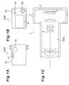
- Fig. 1 is a diagram depicting an electronic still camera (optical apparatus) according to the present embodiment, where Fig. 1A is a front view, Fig. 1B is a rear view, and Fig. 1C is a cross-sectional view along the A-A' line in Fig. 1A ;
- Fig. 2 is a diagram depicting a configuration and zoom locus of a zoom lens according to Example 1;
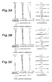
- Fig. 3A are graphs showing various aberrations of the zoom lens according to Example 1 upon focusing on infinity in the wide-angle end state
- Fig. 3B are graphs showing various aberrations of the zoom lens according to Example 1 upon focusing on infinity in the intermediate focal length state
- Fig. 3C are graphs showing various aberrations of the zoom lens according to Example 1 upon focusing on infinity in the telephoto end state;
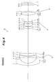
- Fig. 4 is a diagram depicting a configuration and zoom locus of a zoom lens according to Example 2;
- Fig. 5A are graphs showing various aberrations of the zoom lens according to Example 2 upon focusing on infinity in the wide-angle end state
- Fig. 5B are graphs showing various aberrations of the zoom lens according to Example 2 upon focusing on infinity in the intermediate focal length state
- Fig. 5C are graphs showing various aberrations of the zoom lens according to Example 2 upon focusing on infinity in the telephoto end state;
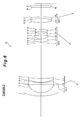
- Fig. 6 is a diagram depicting a configuration and zoom locus of a zoom lens according to Example 3.
- Fig. 7A are graphs showing various aberrations of the zoom lens according to Example 3 upon focusing on infinity in the wide-angle end state
- Fig. 7B are graphs showing various aberrations of the zoom lens according to Example 3 upon focusing on infinity in the intermediate focal length state
- Fig. 7C are graphs showing various aberrations of the zoom lens according to Example 3 upon focusing on infinity in the telephoto end state
- Fig. 8 is a flow chart depicting a manufacturing method for the zoom lens.
- Fig. 1 shows an electronic still camera equipped with a later mentioned zoom lens according to the embodiment, where Fig. 1A is a front view, and Fig. 1B is a rear view.
- Fig. 1C is a cross-sectional view along the A-A' line in Fig. 1A .
- an unillustrated shutter of a camera lens 2 is opened, and lights from an unillustrated object are condensed by the camera lens 2, and an image is formed on an image sensing device C (e.g. CCD, CMOS) disposed on an image plane I.
- the object image formed on the image sensing device C is displayed on a liquid crystal monitor 3 disposed in the back of the electronic still camera 1.
- a user determines a composition of the object image while viewing the liquid crystal monitor 3, then pushes a release button 4 down to shoot the object image by the image sensing device C, and records and stores the image in an unillustrated memory.
- the camera lens 2 is the later mentioned zoom lens ZL according to the present embodiment.
- an auxiliary light emission unit 5 which emits auxiliary light when the object is dark
- a wide (W) - tele (T) button 6 which zooms a lens system 2, that is the camera lens 2 from the wide-angle end state (W) to the telephoto end state (T)
- a function button 7 which is sued for setting various conditions of the electronic still camera 1 are disposed.
- the electronic still camera 1 enclosing the later mentioned zoom lens ZL according to the present embodiment is constructed.
- the zoom lens ZL according to the present embodiment used as the camera lens 2, is comprised of a first lens group G1 having negative refractive power, a second lens group G2 having positive refractive power, and a third lens group G3 having a positive refractive power, which are disposed in order from an object.
- the zoom lens ZL when a focal length changes (zooms) from the wide-angle end state to the telephoto end state, the first lens group G1 is moved in a convex locus facing the image, the second lens group G2 is moved toward the object, and the third lens group G3 is moved toward the image, so that the distance between the first lens group G1 and the second lens group G2 decreases, and the distance between the second lens group G2 and the third lens group G3 increases (see Fig. 2 ).
- An aperture stop S for adjusting quantity of light is disposed between the first lens group G1 and the second lens group G2, and the aperture stop S is moved together with the second lens group G2 upon zooming from the wide-angle end state to the telephoto end state.
- the lens diameter of the first lens group G1 can be decreased, and the position of an exit pupil can be distant from the image plane.
- a filter FL to cut the wavelength in an infrared band is disposed between the zoom lens ZL and the image plane I (image sensing device).
- the zoom lens ZL according to the present embodiment is a negative-lead type zoom lens in which a lens group having negative refractive power disposed closest to the object side, that is the first lens group G1, is disposed. Because of this, the height of the maximum angle of view ray from the optical axis in the wide-angle end state can be deceased. So a diameter of the front lens, that is the lens positioned closest to the object, can be decreased.
- zooming from the wide-angle end state to the telephoto end state is largely performed by changing the image forming magnification of the second lens group G2, so if the aberrations in the second lens group G2 are not well corrected, aberration fluctuation due to zooming becomes a major issue, and increasing the variable power ratio becomes difficult. Also in the telephoto end state where the magnification of the second lens group G2 is high, the relative sensitivity of each lens in the second lens group G2 verses the decentering becomes high, and a performance drop due to manufacturing dispersion increases.
- At least two positive lenses having an aspherical surface respectively are disposed in the second lens group G2, whereby correction of spherical aberration, coma aberration and curvature of field can be distributed to these aspherical surfaces respectively, and aberration fluctuation due to zooming can be decreased even if the variable power ratio is increased. Performance deterioration due to decentering of the aspherical lens can also be decreased.
- one of at least two positive lenses having the aspherical surface disposed in the second lens group is disposed closest to the image in the second lens group G2.
- the second lens group G2 has a first positive lens, a cemented lens and a second positive lens, which are disposed in order from the object.
- the third lens group is moved facing the image upon zooming from the wide-angle end state to the telephoto end state.
- the variable power ratio can be increased without increasing the size of the zoom lens ZL, and astigmatism in the intermediate focal length state in zooming can be appropriately corrected.
- the third lens group G3 is a cemented lens of a positive lens and a negative lens.
- the third lens group G3 is a cemented lens, lateral chromatic aberration can be well corrected in the entire area of zooming.
- the third lens group G3 is a focusing lens group. By this, aberration fluctuation upon focusing can be effectively suppressed.
- At least one of the at least two positive lenses having the aspherical surface in the second lens group G2 satisfies a condition of the following expression (1) ⁇ d > 70 where vd is an Abbe number.
- the above condition expression (1) is for appropriately specifying an Abbe number of a material of the positive lens having the aspherical surface in the second lens group G2.
- the condition expression (1) like this, axial chromatic aberration and lateral chromatic aberration in the telephoto end state can be decreased, and good optical performance with high contrast can be implemented.
- the lower limit value of the conditional expression (1) is 75. It is even more preferable that the lower limit value of the conditional expression (1) is 80.
- the lens disposed closest to the image in the second lens group G2 satisfies a condition of the following expression (2), ⁇ dL > 70 where vdL is an Abbe number.
- the above conditional expression (2) is for appropriately specifying an Abbe number of a material of the image side lens in the second lens group G2.
- the conditional expression (2) By satisfying the conditional expression (2), the chromatic coma aberration in the wide-angle end state can be decreased, and good optical performance can be implemented.
- the lower limit value of the conditional expression (2) it is preferable that the lower limit value of the conditional expression (2) is 75. It is even more preferable that the lower limit value of the conditional expression (2) is 80.
- f2 is a focal length of the second lens group G2
- f2L is a focal length of the lens which is disposed closest to the image in the second lens group G2.
- the above conditional expression (3) is for appropriately specifying a relationship of a focal length f2 of the second lens group G2 and a focal length f2L of the lens which is disposed closest to the image in the second lens group G2.
- good optical performance can be implemented throughout all areas of zooming. If the lower limit value of the conditional expression (3) is not reached, the refractive power of the lens disposed closest to the image, with respect to the entire second lens group G2, decreases, and the function of the aspherical surface decreases, and coma aberration and astigmatism worsen.
- the lower limit value of the conditional expression (3) is 0.2.
- the upper limit value of the conditional expression (3) is 0.4.
- f2 is a focal length of the second lens group G2
- f2c is a focal length of a cemented lens of the second lens group G2.
- the above conditional expression (4) is for appropriately specifying a relationship of a focal length f2 of the second lens group G2 and a focal length f2c of the cemented lens of the second lens group G2.
- good optical performance with less performance deterioration due to manufacturing dispersion can be implemented.
- the lower limit value of the conditional expression (4) is not reached, the negative refractive power of the cemented lens increases, and deterioration of performance due to decentering, particularly decentering coma aberration in the telephoto end state increases, which makes it impossible to maintain good optical performance.
- the lower limit value of the conditional expression (4) is -0.4.
- the upper limit value of the conditional expression (4) is 0.3.
- the zoom lens ZL it is preferable that at least two lenses of the second lens group G2 satisfy a condition of the following expression (5) ⁇ d ⁇ 2 > 70 where vd2 is an Abbe number.
- the above conditional expression (5) is for appropriately specifying an Abbe number of a material of the lens disposed in the second lens group G2.
- axial chromatic aberration particularly axial chromatic aberration in the telephoto end state, can be well corrected.
- the lower limit value of the conditional expression (5) is 75. It is even more preferable that the lower limit value of the conditional expression (5) is 80.
- the zoom lens ZL it is preferable that a condition of the following expression (6) 0.03 ⁇ Dm ⁇ 3 / f ⁇ 3 ⁇ 0.20 is satisfied, where Dm3 is an absolute value of the moving distance of the third lens group G3 upon zooming from the wide-angle end state to the telephoto end state, and f3 is a focal length of the third lens group G3.
- the above conditional expression (6) is for appropriately specifying a relationship of a moving distance Dm3 of the third lens group G3 upon zooming and a focal length f3 of the third lens group G3.
- the conditional expression (6) high variable power ratio and good optical performance can be implemented. If the lower limit value of the conditional expression (6) is not reached, the function of zooming of the third lens G3 decreases, and the moving distance of the second lens group G2 increases to increase the variable power ratio, therefore the size of the lens increases. Correction of astigmatism also becomes difficult.
- the lower limit value of the conditional expression (6) is 0.05.
- the upper limit value of the conditional expression (6) is 0.15.
- At least one surface of the aspherical surfaces of the second lens group G2 has a shape where positive refractive power decreases or negative refractive power increases when approaching from the optical axis to the peripheral area, and a condition of the following expression (7) 0.002 ⁇ Sag / h ⁇ 0.05 is satisfied, where Sag is a sag amount that is a distance in the optical axis direction between the aspherical surface and the proxial reference surface at the maximum effective ray height, and h is a maximum effective ray height h on the aspherical surface.
- the above conditional expression (7) is for appropriately specifying an aspherical shape of the second lens group G2.
- spherical aberration is corrected and good optical performance can be maintained.
- the lower limit value of the conditional expression (7) is not reached, the effect of applying the aspherical surface weakens, which makes the correction of the spherical aberration difficult.
- the upper limit value of the conditional expression (7) is exceeded, on the other hand, deterioration of performance due to decentering, particularly the decentering coma aberration in the telephoto end state increases, which makes it impossible to maintain good optical performance.
- the zoom lens ZL (Lens System) according to each example is comprised of a first lens group G1 having negative refractive power, a second lens group G2 having positive refractive power, and a third lens group G3 having positive refractive power, which are disposed in order from an object, as mentioned above.
- An aperture stop S for adjusting the quantity of light is disposed between the first lens group G1 and the second lens group G2.
- a filter FL to cut the wavelength in an infrared band is disposed between the third lens group G3 and the image plane I.
- the image plane I is formed on an unillustrated image sensing device, and the image sensing device is CCD, CMOS or the like.
- the first lens group G1 is moved along the optical axis in a convex locus facing the image
- the second lens group G2 is moved toward the object
- the third lens group G3 is moved toward the image upon zooming from the wide-angle end state to the telephoto end state, so that the distance between the first lens group G1 and the second lens group G2 decreases, and the distance between the second lens group G2 and the third lens group G3 increases.
- the aperture stop S is moved along with the second lens group G2 upon zooming from the wide-angle end state to the telephoto end state.
- Table 1 to Table 3 shown below are tables on parameters in Example 1 to Example 3.
- f is a focal length
- FNo is an F number
- ⁇ is a half angel of view
- Y is an image height
- TL is a total lens length
- Bf is a back focus.
- the surface number is a sequence of the lens surface from the object along the traveling direction of a ray
- r is a radius of curvature of each lens surface
- d is a surface distance, which is a distance from each optical surface to the next optical surface (or image plane)
- nd is a refractive index with respect to the d-line (wavelength: 587.56 nm)
- vd is an Abbe number.
- values corresponding to the conditional expressions (1) to(7) are also shown.
- mm is generally used to indicate the unit of focal length f, radius of curvature r, surface distance d and other lengths.
- the unit is not limited to "mm", but another appropriate unit may be used.
- "0.0000" of the radius of curvature indicates a plane or an aperture, and the refractive index "1.00000" of the air is omitted.
- an aspherical surface indicated by "*" is given by the following expression (a), where y is the height in a direction perpendicular to the optical axis, S (y) is a distance (Sag amount) along the optical axis from the tangential plane at the vertex of the aspherical surface to a position of the aspherical surface at a height y, r is a radius of curvature of the reference spherical surface (paraxial radius of curvature), K is a conical coefficient, and An is an aspherical coefficient of degree n. In each example, a quadric aspherical coefficient A2 is 0, which is omitted in the tables. En means ⁇ 10 n .
- 1.234E-05 1.234 ⁇ 10 -5 .
- S y y 2 / r / 1 + 1 - K ⁇ y 2 / r 2 1 / 2 + A ⁇ 4 ⁇ y 4 + A ⁇ 6 + y 6 + A ⁇ 8 ⁇ y 8 + A ⁇ 10 ⁇ y 10
- Fig. 2 shows the lens configuration and the zooming locus of Example 1.
- a first lens group G1 is comprised of a negative meniscus lens L11 having a concave surface facing the image, a biconcave negative lens L12, and a positive meniscus lens L13 having a convex surface facing the object, which are disposed in order from the object, and the lens surfaces facing the object and the image of the negative meniscus lens L11 are aspherical.
- a second lens group G2 is comprised of a positive meniscus lens L21 (first positive lens) having a convex surface facing the object, a cemented lens of a positive meniscus lens L22 having a convex surface facing the object and a negative meniscus lens L23 having a concave surface facing the image, and a positive meniscus lens L24 (second positive lens) having a convex surface facing the object, which are disposed in order from the object, and the lens surface facing the object of the positive meniscus lens L22 (first positive lens) and the lens surface facing the image side of the positive meniscus lens L24 (second positive lens) are aspherical.
- the third lens group G3 is a cemented lens of a biconvex positive lens L31 and a negative meniscus lens L32 having a concave surface facing the object, which are disposed in order from the object.
- Table 1 shows each parameter in Example 1.
- the surface numbers 1 to 19 in Table 1 correspond to the surfaces 1 to 19 in Fig. 2 .
- each lens surface of the first surface, second surface, tenth surface and fourteenth surface are formed to be aspherical.
- D6, D14 and D17 are variable distances.
- the zoom lens ZL according to the present example satisfies all the conditional expressions (1) to (7).
- Fig. 3 are graphs showing various aberrations of Example 1.
- FNo indicates an F number
- Y indicates an image height.
- d shows various aberrations with respect to the d-line (wavelength: 587.6 nm)
- g shows various aberrations with respect to the g-line (wavelength: 435.8 nm)
- aberrations with no indication show aberrations with respect to the d-line.
- the solid line indicates a sagittal image surface
- a broken line indicates a meridional image surface.
- the graph showing coma aberration is based on a half angle of view. The above description on the graphs showing aberrations is the same for other examples, where this description will be omitted.
- Example 1 As each graph showing aberrations clarifies, in Example 1, various aberrations in each focal length state from the wide-angle end state to the telephoto end state are well corrected, and an excellent image forming performance is implemented.
- Fig. 4 shows the lens configuration and the zooming locus of Example 2.
- a first lens group G1 is comprised of a negative meniscus lens L11 having a concave surface facing the image, a biconcave negative lens L12, and a positive meniscus lens L13 having a convex surface facing the object, which are disposed in order from the object, and the lens surfaces facing the object and the image of the negative meniscus lens L11 are aspherical.
- a second lens group G2 is comprised of a positive meniscus lens L21 (first positive lens) having a convex surface facing the object, a cemented lens of a positive meniscus lens L22 having a convex surface facing the object and a negative meniscus lens L23 having a concave surface facing the image, and a positive meniscus lens L24 (second positive lens) having a convex surface facing the object, which are disposed in order from the object, and the lens surface facing the object of the positive meniscus lens L22 (first positive lens) and the lens surface facing the image side of the positive meniscus lens L24 (second positive lens) are aspherical.
- the third lens group G3 is a cemented lens of a biconvex positive lens L31 and a negative meniscus lens L32 having a concave surface facing the object, which are disposed in order from the object.
- Table 2 shows each parameter in Example 2.
- the surface numbers 1 to 19 in Table 2 correspond to the surfaces 1 to 19 in Fig. 4 .
- each lens surface of the first surface, second surface, tenth surface and thirteenth surface are formed to be aspherical.
- D6, D14 and D17 are variable distances.
- the zoom lens ZL according to the present example satisfies all the conditional expressions (1) to (7).
- Fig. 5 are graphs showing various aberrations of Example 2.
- Example 2 As each graph showing aberrations clarifies, in Example 2, various aberrations in each focal length state from the wide-angle end state to the telephoto end state are well corrected, and an excellent image forming performance is implemented.
- Fig. 6 shows the lens configuration and the zooming locus of Example 3.
- a first lens group G1 is comprised of a negative meniscus lens L11 having a concave surface facing the image, a biconcave negative lens L12, and a positive meniscus lens L13 having a convex surface facing the object, which are disposed in order from the object, and the lens surfaces facing the object and the image of the negative meniscus lens L11 are aspherical.
- a second lens group G2 is comprised of a positive meniscus lens L21 (first positive lens) having a convex surface facing the object, a cemented lens of a biconvex positive lens L22 having a convex surface facing the object and a biconcave negative lens L23 having a concave surface facing the image, and a biconvex positive lens L24 (second positive lens) having a convex surface facing the object, which are disposed in order from the object, and the lens surface facing the object of the biconvex positive lens L22 (first positive lens) and the lens surface facing the image side of the biconcave positive lens L24 (second positive lens) are aspherical.
- the third lens group G3 is a cemented lens of a biconvex positive lens L31 and a negative meniscus lens L32 having a concave surface facing the object, which are disposed in order from the object.
- Table 3 shows each parameter in Example 3.
- the surface numbers 1 to 19 in Table 3 correspond to the surfaces 1 to 19 in Fig. 6 .
- each lens surface of the first surface, second surface, tenth surface and thirteenth surface are formed to be aspherical.
- D6, D14 and D17 are variable distances.
- the zoom lens ZL according to the present example satisfies all the conditional expressions (1) to (7).
- Fig. 7 are graphs showing various aberrations of Example 3.
- Example 3 As each graph showing aberrations clarifies, in Example 3, various aberrations in each focal length state from the wide-angle end state to the telephoto end state are well corrected, and an excellent image forming performance is implemented.
- a manufacturing method for a zoom lens which has a first lens group having negative refractive power, a second lens group having positive refractive power, and a third lens group having positive refractive power, which are disposed in order from the object, will now be described with reference to Fig. 8 .
- the manufacturing method further has a step of disposing one positive lens out of at least two positive lenses having an aspherical surface which are disposed as the second lens group, is disposed closest to the image in the second lens group.
- the lens disposed closest to the image in the second lens group satisfies a condition of the expression vdL > 70, where vdL is an Abbe number.
- the zoom lens satisfies a condition of the expression 0.1 ⁇ f2 / f2L ⁇ 0.6, where f2 is a focal length of the second lens group, and f2L is a focal length of the lens disposed closest to the image in the image in the second lens group.
- the following content can be used if appropriate, within a range where the optical performance is not diminished.
- the zoom lens ZL comprised of three groups was shown, but the present invention can also be applied to other configurations, such as a four-group or five-group configuration.
- a single lens group, or a plurality of lens groups, or a partial lens group may be a focusing lens group which focuses on an object from infinity to a short range by moving in an optical axis direction.
- the focusing lens group can also be applied to auto focus, and is also appropriate for a driving motor for auto focus (e.g. ultrasonic motor). It is preferable that the first lens group G1 or the third lens group G3, particularly the third lens group G3, is the focus lens group.
- a lens group or a partial lens group may be a vibration proof lens group which is vibrated in a direction perpendicular to the optical axis, so as to correct image blur generated by hand motion. It is particularly preferable that all or part of the second lens group G2 is a vibration proof lens group.
- Each lens surface may be aspherical.
- the aperture stop S is preferably disposed between the first lens group G1 and the second lens group G2, but a lens frame may play the role of an aperture stop S, without disposing a separate element of an aperture stop S.
- An anti-reflection film having high transmittance in a wide wavelength area may be formed on each lens surface to decrease flares and ghosts, so that a high optical performance with high contrast may be implemented.
Landscapes
- Physics & Mathematics (AREA)
- General Physics & Mathematics (AREA)
- Optics & Photonics (AREA)
- Nonlinear Science (AREA)
- Lenses (AREA)
- Studio Devices (AREA)
Priority Applications (1)
| Application Number | Priority Date | Filing Date | Title |
|---|---|---|---|
| EP18183667.7A EP3428706A3 (fr) | 2008-03-03 | 2009-02-25 | Lentille de zoom et appareil optique équipé de cette lentille de zoom |
Applications Claiming Priority (1)
| Application Number | Priority Date | Filing Date | Title |
|---|---|---|---|
| JP2008052610A JP5433958B2 (ja) | 2008-03-03 | 2008-03-03 | ズームレンズ及びこれを備えた光学機器 |
Related Child Applications (2)
| Application Number | Title | Priority Date | Filing Date |
|---|---|---|---|
| EP18183667.7A Division-Into EP3428706A3 (fr) | 2008-03-03 | 2009-02-25 | Lentille de zoom et appareil optique équipé de cette lentille de zoom |
| EP18183667.7A Division EP3428706A3 (fr) | 2008-03-03 | 2009-02-25 | Lentille de zoom et appareil optique équipé de cette lentille de zoom |
Publications (2)
| Publication Number | Publication Date |
|---|---|
| EP2098899A1 true EP2098899A1 (fr) | 2009-09-09 |
| EP2098899B1 EP2098899B1 (fr) | 2018-09-26 |
Family
ID=40578399
Family Applications (2)
| Application Number | Title | Priority Date | Filing Date |
|---|---|---|---|
| EP09250506.4A Ceased EP2098899B1 (fr) | 2008-03-03 | 2009-02-25 | Lentille de zoom et appareil optique équipé de cette lentille de zoom |
| EP18183667.7A Withdrawn EP3428706A3 (fr) | 2008-03-03 | 2009-02-25 | Lentille de zoom et appareil optique équipé de cette lentille de zoom |
Family Applications After (1)
| Application Number | Title | Priority Date | Filing Date |
|---|---|---|---|
| EP18183667.7A Withdrawn EP3428706A3 (fr) | 2008-03-03 | 2009-02-25 | Lentille de zoom et appareil optique équipé de cette lentille de zoom |
Country Status (4)
| Country | Link |
|---|---|
| US (1) | US8218242B2 (fr) |
| EP (2) | EP2098899B1 (fr) |
| JP (1) | JP5433958B2 (fr) |
| CN (1) | CN101526667B (fr) |
Families Citing this family (7)
| Publication number | Priority date | Publication date | Assignee | Title |
|---|---|---|---|---|
| JP5110451B2 (ja) * | 2010-08-31 | 2012-12-26 | 株式会社ニコン | ズームレンズ、光学機器及びズームレンズの製造方法 |
| JP5344633B2 (ja) * | 2010-11-10 | 2013-11-20 | キヤノン株式会社 | 撮像装置 |
| JP5676505B2 (ja) | 2011-04-07 | 2015-02-25 | パナソニックIpマネジメント株式会社 | ズームレンズ系、撮像装置及びカメラ |
| JP5871630B2 (ja) * | 2012-01-23 | 2016-03-01 | キヤノン株式会社 | ズームレンズ及びそれを有する撮像装置 |
| CN104076492B (zh) * | 2013-03-29 | 2017-01-18 | 佳能株式会社 | 透镜装置和包括透镜装置的图像拾取装置 |
| CN103197409B (zh) * | 2013-04-01 | 2017-12-26 | 东莞市宇瞳光学科技股份有限公司 | 光学补偿变焦镜头 |
| EP3343261B1 (fr) * | 2016-12-27 | 2022-05-18 | Canon Kabushiki Kaisha | Système optique de capture d'image, appareil de capture d'image ayant le système optique de capture d'image, appareil de lentille ayant le système optique de capture d'image et système de capture d'image ayant le système optique de capture d'image |
Citations (4)
| Publication number | Priority date | Publication date | Assignee | Title |
|---|---|---|---|---|
| JP2007065514A (ja) | 2005-09-01 | 2007-03-15 | Ricoh Co Ltd | 光学系及び撮像装置 |
| JP2007248796A (ja) * | 2006-03-16 | 2007-09-27 | Mark:Kk | ズームレンズ |
| EP1873569A1 (fr) * | 2006-06-30 | 2008-01-02 | Ricoh Company, Ltd. | Objectif de zoom, appareil photographique et assistant numérique personnel |
| JP2008052610A (ja) | 2006-08-28 | 2008-03-06 | Sanyo Electric Co Ltd | ポインタ表示制御装置及びポインタ表示制御プログラム |
Family Cites Families (19)
| Publication number | Priority date | Publication date | Assignee | Title |
|---|---|---|---|---|
| JP3897457B2 (ja) * | 1998-07-01 | 2007-03-22 | キヤノン株式会社 | 立体画像撮影用光学系およびそれに用いるズームレンズ |
| JP4507140B2 (ja) * | 2000-02-28 | 2010-07-21 | フジノン株式会社 | 3群ズームレンズ |
| JP3711059B2 (ja) * | 2001-10-24 | 2005-10-26 | 株式会社リコー | カメラ |
| JP4555522B2 (ja) * | 2001-09-28 | 2010-10-06 | 株式会社リコー | ズームレンズ、カメラ及び携帯情報端末装置 |
| JP4294299B2 (ja) | 2001-11-26 | 2009-07-08 | オリンパス株式会社 | ズームレンズ及びそれを用いた電子撮像装置 |
| JP4181851B2 (ja) * | 2002-11-01 | 2008-11-19 | 株式会社リコー | ズームレンズ、カメラおよび携帯情報端末装置 |
| JP4346977B2 (ja) * | 2003-07-03 | 2009-10-21 | 株式会社リコー | 可変焦点距離レンズ、撮影レンズユニット、カメラおよび携帯情報端末装置 |
| JP4540387B2 (ja) | 2004-04-30 | 2010-09-08 | オリンパス株式会社 | ズームレンズおよび撮像装置 |
| US7092170B2 (en) | 2004-04-30 | 2006-08-15 | Olympus Corporation | Zoom lens and image pickup apparatus |
| JP4892892B2 (ja) * | 2004-09-15 | 2012-03-07 | 株式会社ニコン | 広角ズームレンズ |
| JP2006084736A (ja) * | 2004-09-15 | 2006-03-30 | Nikon Corp | ワイドコンバーターレンズ |
| JP4882263B2 (ja) * | 2005-03-31 | 2012-02-22 | 株式会社ニコン | ズームレンズ |
| JP4916198B2 (ja) * | 2006-03-20 | 2012-04-11 | 株式会社リコー | ズームレンズ、ズームレンズを有する撮像装置、カメラ装置および携帯情報端末装置 |
| JP4923764B2 (ja) | 2006-06-12 | 2012-04-25 | 株式会社ニコン | ズームレンズとこれを有する光学装置 |
| CN100520481C (zh) * | 2006-06-30 | 2009-07-29 | 株式会社理光 | 变焦透镜,拍摄设备和个人数字助理 |
| JP4983126B2 (ja) * | 2006-07-24 | 2012-07-25 | カシオ計算機株式会社 | ズームレンズ及びプロジェクタ装置 |
| US7535650B2 (en) * | 2006-11-27 | 2009-05-19 | Ricoh Company, Ltd. | Zoom lens, image pickup apparatus, and personal digital assistant |
| JP2008134323A (ja) * | 2006-11-27 | 2008-06-12 | Ricoh Co Ltd | 撮像用のズームレンズ及び撮像装置 |
| JP5072075B2 (ja) | 2006-11-27 | 2012-11-14 | 株式会社リコー | ズームレンズおよび撮像装置および携帯情報端末装置 |
-
2008
- 2008-03-03 JP JP2008052610A patent/JP5433958B2/ja not_active Expired - Fee Related
-
2009
- 2009-02-25 EP EP09250506.4A patent/EP2098899B1/fr not_active Ceased
- 2009-02-25 EP EP18183667.7A patent/EP3428706A3/fr not_active Withdrawn
- 2009-02-27 US US12/394,102 patent/US8218242B2/en not_active Expired - Fee Related
- 2009-03-03 CN CN2009101182576A patent/CN101526667B/zh not_active Expired - Fee Related
Patent Citations (4)
| Publication number | Priority date | Publication date | Assignee | Title |
|---|---|---|---|---|
| JP2007065514A (ja) | 2005-09-01 | 2007-03-15 | Ricoh Co Ltd | 光学系及び撮像装置 |
| JP2007248796A (ja) * | 2006-03-16 | 2007-09-27 | Mark:Kk | ズームレンズ |
| EP1873569A1 (fr) * | 2006-06-30 | 2008-01-02 | Ricoh Company, Ltd. | Objectif de zoom, appareil photographique et assistant numérique personnel |
| JP2008052610A (ja) | 2006-08-28 | 2008-03-06 | Sanyo Electric Co Ltd | ポインタ表示制御装置及びポインタ表示制御プログラム |
Also Published As
| Publication number | Publication date |
|---|---|
| CN101526667B (zh) | 2012-09-19 |
| EP2098899B1 (fr) | 2018-09-26 |
| JP5433958B2 (ja) | 2014-03-05 |
| CN101526667A (zh) | 2009-09-09 |
| JP2009210741A (ja) | 2009-09-17 |
| EP3428706A3 (fr) | 2019-04-10 |
| EP3428706A2 (fr) | 2019-01-16 |
| US20090225437A1 (en) | 2009-09-10 |
| US8218242B2 (en) | 2012-07-10 |
Similar Documents
| Publication | Publication Date | Title |
|---|---|---|
| US8023198B2 (en) | Lens system and optical apparatus having this lens system | |
| EP2620796B1 (fr) | Système optique et appareil d'imagerie | |
| CN102955230B (zh) | 变焦镜头和成像设备 | |
| EP2360504A1 (fr) | Système de lentilles de zoom, appareil optique et procédé de fabrication de lentilles de zoom | |
| JP2010014963A (ja) | ズームレンズ、撮像装置、ズームレンズの変倍方法 | |
| CN104508532B (zh) | 变焦镜头、光学设备和用于制造变焦镜头的方法 | |
| JP2015191065A (ja) | ズームレンズ、撮像装置及びズームレンズの製造方法 | |
| US8218242B2 (en) | Zoom lens and optical apparatus equipped with this zoom lens | |
| US9645366B2 (en) | Zoom lens, optical apparatus, and method for manufacturing the zoom lens | |
| JP5622103B2 (ja) | ズームレンズ、このズームレンズを搭載した光学機器、及び、ズームレンズの製造方法 | |
| JP5510784B2 (ja) | ズームレンズ、光学機器 | |
| EP2325681B1 (fr) | Lentille de zoom, appareil optique et procédé de fabrication de lentille de zoom | |
| JP5151068B2 (ja) | レンズ系とこれを有する光学装置 | |
| JP6354257B2 (ja) | 変倍光学系及び撮像装置 | |
| JP2016157076A (ja) | ズームレンズ、光学機器及びズームレンズの製造方法 | |
| US9140882B2 (en) | Zoom lens, optical apparatus, and method for manufacturing the zoom lens | |
| EP2482112A1 (fr) | Lentille de zoom, appareil optique et procédé de fabrication de lentille de zoom | |
| JP2016157075A (ja) | ズームレンズ、光学機器及びズームレンズの製造方法 | |
| JP5505770B2 (ja) | ズームレンズ、光学機器 | |
| JP7052832B2 (ja) | ズームレンズおよび光学機器 | |
| JP5115871B2 (ja) | ズームレンズ、光学機器及びズームレンズの製造方法 | |
| CN107250871B (zh) | 变焦镜头以及光学设备 | |
| JP2016156903A (ja) | ズームレンズ、光学機器及びズームレンズの製造方法 | |
| JP2016156902A (ja) | ズームレンズ、光学機器及びズームレンズの製造方法 | |
| JP2016156940A (ja) | ズームレンズ、光学機器及びズームレンズの製造方法 |
Legal Events
| Date | Code | Title | Description |
|---|---|---|---|
| PUAI | Public reference made under article 153(3) epc to a published international application that has entered the european phase |
Free format text: ORIGINAL CODE: 0009012 |
|
| AK | Designated contracting states |
Kind code of ref document: A1 Designated state(s): AT BE BG CH CY CZ DE DK EE ES FI FR GB GR HR HU IE IS IT LI LT LU LV MC MK MT NL NO PL PT RO SE SI SK TR |
|
| AX | Request for extension of the european patent |
Extension state: AL BA RS |
|
| 17P | Request for examination filed |
Effective date: 20100309 |
|
| AKX | Designation fees paid |
Designated state(s): DE FR GB |
|
| RAP1 | Party data changed (applicant data changed or rights of an application transferred) |
Owner name: NIKON CORPORATION |
|
| RAP1 | Party data changed (applicant data changed or rights of an application transferred) |
Owner name: NIKON CORPORATION |
|
| STAA | Information on the status of an ep patent application or granted ep patent |
Free format text: STATUS: EXAMINATION IS IN PROGRESS |
|
| 17Q | First examination report despatched |
Effective date: 20170321 |
|
| GRAP | Despatch of communication of intention to grant a patent |
Free format text: ORIGINAL CODE: EPIDOSNIGR1 |
|
| STAA | Information on the status of an ep patent application or granted ep patent |
Free format text: STATUS: GRANT OF PATENT IS INTENDED |
|
| INTG | Intention to grant announced |
Effective date: 20180108 |
|
| GRAS | Grant fee paid |
Free format text: ORIGINAL CODE: EPIDOSNIGR3 |
|
| GRAA | (expected) grant |
Free format text: ORIGINAL CODE: 0009210 |
|
| STAA | Information on the status of an ep patent application or granted ep patent |
Free format text: STATUS: THE PATENT HAS BEEN GRANTED |
|
| AK | Designated contracting states |
Kind code of ref document: B1 Designated state(s): DE FR GB |
|
| REG | Reference to a national code |
Ref country code: GB Ref legal event code: FG4D |
|
| REG | Reference to a national code |
Ref country code: DE Ref legal event code: R096 Ref document number: 602009054722 Country of ref document: DE |
|
| REG | Reference to a national code |
Ref country code: DE Ref legal event code: R097 Ref document number: 602009054722 Country of ref document: DE |
|
| PLBE | No opposition filed within time limit |
Free format text: ORIGINAL CODE: 0009261 |
|
| STAA | Information on the status of an ep patent application or granted ep patent |
Free format text: STATUS: NO OPPOSITION FILED WITHIN TIME LIMIT |
|
| 26N | No opposition filed |
Effective date: 20190627 |
|
| PGFP | Annual fee paid to national office [announced via postgrant information from national office to epo] |
Ref country code: FR Payment date: 20210113 Year of fee payment: 13 |
|
| PGFP | Annual fee paid to national office [announced via postgrant information from national office to epo] |
Ref country code: GB Payment date: 20210217 Year of fee payment: 13 Ref country code: DE Payment date: 20210209 Year of fee payment: 13 |
|
| REG | Reference to a national code |
Ref country code: DE Ref legal event code: R119 Ref document number: 602009054722 Country of ref document: DE |
|
| GBPC | Gb: european patent ceased through non-payment of renewal fee |
Effective date: 20220225 |
|
| PG25 | Lapsed in a contracting state [announced via postgrant information from national office to epo] |
Ref country code: FR Free format text: LAPSE BECAUSE OF NON-PAYMENT OF DUE FEES Effective date: 20220228 |
|
| PG25 | Lapsed in a contracting state [announced via postgrant information from national office to epo] |
Ref country code: GB Free format text: LAPSE BECAUSE OF NON-PAYMENT OF DUE FEES Effective date: 20220225 Ref country code: DE Free format text: LAPSE BECAUSE OF NON-PAYMENT OF DUE FEES Effective date: 20220901 |