EP2098932A2 - Appareil de gestion d'instrument de champ - Google Patents
Appareil de gestion d'instrument de champ Download PDFInfo
- Publication number
- EP2098932A2 EP2098932A2 EP09002869A EP09002869A EP2098932A2 EP 2098932 A2 EP2098932 A2 EP 2098932A2 EP 09002869 A EP09002869 A EP 09002869A EP 09002869 A EP09002869 A EP 09002869A EP 2098932 A2 EP2098932 A2 EP 2098932A2
- Authority
- EP
- European Patent Office
- Prior art keywords
- instrument
- field
- acquired
- address
- tag name
- Prior art date
- Legal status (The legal status is an assumption and is not a legal conclusion. Google has not performed a legal analysis and makes no representation as to the accuracy of the status listed.)
- Withdrawn
Links
Images


Classifications
-
- G—PHYSICS
- G05—CONTROLLING; REGULATING
- G05B—CONTROL OR REGULATING SYSTEMS IN GENERAL; FUNCTIONAL ELEMENTS OF SUCH SYSTEMS; MONITORING OR TESTING ARRANGEMENTS FOR SUCH SYSTEMS OR ELEMENTS
- G05B19/00—Program-control systems
- G05B19/02—Program-control systems electric
- G05B19/418—Total factory control, i.e. centrally controlling a plurality of machines, e.g. direct or distributed numerical control [DNC], flexible manufacturing systems [FMS], integrated manufacturing systems [IMS] or computer integrated manufacturing [CIM]
- G05B19/4185—Total factory control, i.e. centrally controlling a plurality of machines, e.g. direct or distributed numerical control [DNC], flexible manufacturing systems [FMS], integrated manufacturing systems [IMS] or computer integrated manufacturing [CIM] characterised by the network communication
-
- G—PHYSICS
- G05—CONTROLLING; REGULATING
- G05B—CONTROL OR REGULATING SYSTEMS IN GENERAL; FUNCTIONAL ELEMENTS OF SUCH SYSTEMS; MONITORING OR TESTING ARRANGEMENTS FOR SUCH SYSTEMS OR ELEMENTS
- G05B2219/00—Program-control systems
- G05B2219/30—Nc systems
- G05B2219/31—From computer integrated manufacturing till monitoring
- G05B2219/31394—Field management, low level, instruments and controllers acting in real time
-
- Y—GENERAL TAGGING OF NEW TECHNOLOGICAL DEVELOPMENTS; GENERAL TAGGING OF CROSS-SECTIONAL TECHNOLOGIES SPANNING OVER SEVERAL SECTIONS OF THE IPC; TECHNICAL SUBJECTS COVERED BY FORMER USPC CROSS-REFERENCE ART COLLECTIONS [XRACs] AND DIGESTS
- Y02—TECHNOLOGIES OR APPLICATIONS FOR MITIGATION OR ADAPTATION AGAINST CLIMATE CHANGE
- Y02P—CLIMATE CHANGE MITIGATION TECHNOLOGIES IN THE PRODUCTION OR PROCESSING OF GOODS
- Y02P90/00—Enabling technologies with a potential contribution to greenhouse gas [GHG] emissions mitigation
- Y02P90/02—Total factory control, e.g. smart factories, flexible manufacturing systems [FMS] or integrated manufacturing systems [IMS]
-
- Y—GENERAL TAGGING OF NEW TECHNOLOGICAL DEVELOPMENTS; GENERAL TAGGING OF CROSS-SECTIONAL TECHNOLOGIES SPANNING OVER SEVERAL SECTIONS OF THE IPC; TECHNICAL SUBJECTS COVERED BY FORMER USPC CROSS-REFERENCE ART COLLECTIONS [XRACs] AND DIGESTS
- Y02—TECHNOLOGIES OR APPLICATIONS FOR MITIGATION OR ADAPTATION AGAINST CLIMATE CHANGE
- Y02P—CLIMATE CHANGE MITIGATION TECHNOLOGIES IN THE PRODUCTION OR PROCESSING OF GOODS
- Y02P90/00—Enabling technologies with a potential contribution to greenhouse gas [GHG] emissions mitigation
- Y02P90/80—Management or planning
Definitions
- the present invention relates to a field instrument management apparatus.
- various measurement instruments which are called field instruments on the whole, measure various process values in a plant, and a control apparatus controls all kinds of measurement instruments included in the plant, based on measurement results made by the field instrument.
- the control apparatus and various measurement instruments are connected by a field bus such as Foundation Fieldbus, Highway Address Remote Transducer (HART: registered trademark), and the like.
- the control apparatus communicates with the various measurement instruments through the field bus, so as to achieve control of various process instruments.
- Management of the field instruments is performed regularly based on the maintenance plan of the plant, or when trouble in a system irregularly occurs or field instruments are added and set.
- a management tool which is used for maintenance and the like of the field instruments, FieldMate (registered trademark) disclosed in a Non-Patent document, (refer to " FieldMate FIELD DEVICE MANAGEMENT TOOL FOR THE NEW ERA", Isao Hirooka, Youji Saitou, Mizuo Kawahara, and Hironori Murata, Yokogawa Technical Report English Edition, No. 44, pp. 9-12, 2007 ).
- This management tool is installed in a notebook type personal computer (PC), which is connected with the field bus, and the like.
- the management tool is an application program that enables us to manage settings, adjust various parameters of the field instruments, and perform maintenance of the field instruments.
- the conventional management tool described above acquires all instrument information including an instrument address from the all field instruments primarily, and then, operates management processes of each field instrument, when management of the field instruments is performed. Therefore, when the number of the field instruments is large, it takes a long time to acquire the all instrument information, since a communication speed (transmission speed) of the field bus is relatively slow. For this reason, there is a problem in that the management processes can not be promptly performed. For example, when the six field instruments are connected through the Foundation Fieldbus, it takes about 4 minutes to acquire all of the instrument information from all of the field instruments.
- the present invention was achieved in view of the above circumstances, and has as its object to provide a field instrument management apparatus that can perform the management processes of a filed instrument faster than the conventional case.
- a field instrument management apparatus for managing a field instrument by communicating therewith includes a management unit that transfers a first request, which requests to provide an instrument address, to the field instrument, and provides the instrument address to the outside at a first time at which the instrument address is acquired from the field instrument.
- the field instrument management apparatus of the first aspect wherein the management unit may transfer a second request, which requests to provide an instrument tag name and an instrument identification (ID), to the field instrument at the first time at which the instrument address is acquired from the field instrument, and may provide the instrument tag name and the instrument ID to the outside at a second time at which the instrument tag name and the instrument ID are acquired from the field instrument.
- ID instrument identification
- the field instrument management apparatus of the first aspect may further include an individual management tool that manages the field instrument, wherein, at the second time at which the instrument tag name and the instrument ID are acquired from the field instrument, the individual management tool corresponding to the instrument tag name and the instrument ID is set in a state capable of starting up, and the management unit provides the state to the outside.
- the field instrument management apparatus of the first aspect wherein the individual management tool may transfer a third request, which requests to change a setting of the field instrument, to the field instrument, based on an instruction from the outside, after the second time.
- the field instrument management apparatus of the first aspect may further include a communication portion that includes a local area network (LAN) communication portion, a communication server, and a LAN cable.
- LAN local area network
- the field instrument management apparatus of the first aspect may further include a field bus communication portion that directly communicates with the field instrument.
- the field instrument management apparatus of the first aspect wherein the management unit may manage a plurality of the field instruments.
- the field instrument management apparatus of the first aspect may further include a storage portion that stores each of the acquired instrument address, the acquired instrument tag name, the acquired instrument ID, the management unit, and the individual management tool.
- each of the acquired instrument address, the acquired instrument tag name, and the acquired instrument ID may be provided visually.
- each of the acquired instrument address, the acquired instrument tag name, and the acquired instrument ID may be provided auditorialy.
- the field instrument management apparatus of the first aspect may further include an operation portion.
- the field instrument management apparatus of the first aspect may further include a control and computing portion.
- a control method in which a field instrument management apparatus manages a field instrument by communicating therewith, the control method includes transferring a first request for an instrument address to the field instrument, and providing the instrument address to the outside at a first time at which the instrument address is acquired from the field instrument.
- the control method of the second aspect may further include transferring a second request for an instrument tag name and an instrument identification (ID) to the field instrument at the first time at which the instrument address is acquired from the field instrument, and providing the instrument tag name and the instrument ID to the outside at a second time at which the instrument tag name and the instrument ID are acquired from the field instrument.
- ID instrument identification
- the control method of the second aspect may further include setting an individual management tool corresponding to the instrument tag name and the instrument ID to be in a state capable of starting up, and providing the state to the outside, at the second time at which the instrument tag name and the instrument ID are acquired from the field instrument.
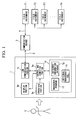
- FIG. 1 is a block diagram that shows a system configuration of a field instrument management system including a client computer (field instrument management apparatus) 1 according to a present embodiment of the present invention.
- This field instrument management system manages a plurality (n-set) of field instruments F1 to Fn, and includes the client computer 1, a local area network (LAN) cable, a communication server 3, and a filed bus 4.
- LAN local area network
- the client computer 1 is a general purpose computer such as a personal computer or the like, and is operated by an operator S (including a user) who engages in monitoring a plant or maintenance of the plant.
- the client computer includes an operation portion 1a such as a keyboard, a mouse and the like, a display portion 1b such as a liquid crystal display and the like, a LAN communication portion 1c that communicates with an outside in accordance with a communication standard of LAN, a storage portion 1d that stores various application programs, an operating system (OS) or the like, the various application programs described above, the operating system, and control and computing portion 1e that controls each of the above-mentioned portions based on the operation information input from the operation portion 1a, received information received by the LAN communication portion 1c, or the like.
- OS operating system
- the storage portion 1d stores a management program 1f, an instrument information database 1g, and an individual management tool 1h, in addition to the operating system (unillustrated).
- the management program 1f is an application program that manages each of the field instruments F1 to Fn.
- the instrument information database 1g contains various attribute information that relates to each of the field instruments F1 to Fn, and is registered in each of the field instruments F1 to Fn as instrument information.
- the instrument information database 1g is assembled by acquiring the instrument information from each of the field instruments F1 to Fn via the LAN cable 2, the communication server 3, and the field bus 4.
- the individual management tool 1h is a management program (application program) which is specialized in each of the field instruments F1 to Fn such as a flow meter, a pressure gage, a thermometer and the like.
- the individual management tool 1h exclusively manages the corresponding field instruments F1 to Fn.
- the LAN cable 2 is a signal cable that includes mechanical and electrical properties in accordance with the communication standard of LAN.
- the LAN cable 2 connects the client computer 1 and the communication server 3 so as to be able to communicate with each other.
- the communication server 3 intermediates a communication between the client computer 1 and each of the field instruments F1 to Fn.
- the communication server 3 acquires the instrument information from each of the field instruments F1 to Fn so as to provide the acquired instrument information to the client computer 1, in response to a request from the client computer 1.
- the field bus 4 is a communication bus which is standardized for communication in the plant, such as Foundation Fieldbus, HART (registered trademark) and the like.
- the field bus 4 connects the communication server 3 and each of the field instruments F1 to Fn so as to be able to communicate with each other.
- FIG. 2 is a sequence diagram that shows an operation of the field instrument management system of the present invention.
- step S1 When a confirmation request (instrument confirmation request) related to each of the field instruments F1 to Fn is input to the client computer 1 by the operator S operating the operation portion 1a (step S1), the client computer 1 transfers an instrument address request to the communication server 3 (step S2). That is, the operation portion 1a of the client computer 1 outputs the instrument confirmation request to the control and computing portion 1e when the client computer 1 receives the instrument confirmation request from the operator S. As a result, the control and computing portion 1e outputs the instrument address request to the LAN communication portion 1c, and allows the LAN communication portion 1c to transfer the instrument address request to the communication server 3.
- the instrument address request described above requests that all of the field instruments F1 to Fn provide the instrument address assigned individually to each of the field instruments F1 to Fn, based on the specification of the field bus 4.
- the communication server 3 transfers a similar instrument address request to all of the field instruments F1 to Fn (step S3).
- each of the field instruments F1 to Fn receives the instrument address request from the communication server 3
- each of the field instruments F1 to Fn transfers (provides) the instrument address stored therein to the communication server 3 (step S4).
- the communication server 3 transfers the instrument address acquired from each of the field instruments F1 to Fn to the client computer 1 (step S5).
- the client computer 1 provides the acquired instrument addresses of all of the field instruments F1 to Fn as described above to the operator S through the display portion 1b (step S6). That is, the control and computing portion 1e of the client computer 1 outputs the instrument address to the display portion 1b so as to display when the instrument address is input from the LAN communication portion 1c.
- the suspended instrument Since the field instrument under suspension (suspended instrument) does not communicate via the communication server 3 and the field bus 4, the suspended instrument does not receive the instrument address request from the communication server 3. Therefore, the suspended instrument does not transfer the instrument address to the communication server 3.
- the communication server 3 transfers an instrument address, which is received only within a predetermined period from sending the instrument address request to each of the field instruments F1 to Fn, to the client computer 1.
- all of the field instruments F1 to Fn are assumed to be in an operation state, and assumed to send the instrument address to the communication server 3.
- FIG. 3 shows a schematic diagram of a management screen that shows the instrument information of the each of the field instruments F1 to Fn.
- the client computer 1 displays the instrument address of each of the field instruments F1 to Fn, as shown on the management screen of FIG. 3 , when the client computer 1 receives the instrument address of each of the field instruments F 1 to Fn from the communication server 3.
- the operator S sees and confirms the management screen, and hence, can recognize which instrument address is used at that time. Accordingly, when, for example, another field instrument is newly added in the plant, the operator sets the instrument address of the added field instrument to an unused instrument address, in other words, an instrument address which is not displayed on the management screen (step S7).
- the client computer 1 when the client computer 1 receives the instrument address from the communication server 3, the client computer 1 transfers an instrument tag name and identification (ID) request, which requests the field instruments F1 to Fn corresponding to the received instrument address to provide an instrument tag name and an ID thereof, to the communication server 3 (step S8). That is, when the instrument address is input from the LAN communication portion 1c, the client computer 1 allows the LAN communication portion 1c to transfer the instrument tag name and ID request to the communication server 3. Then, when the communication server 3 receives the instrument tag name and ID request, the communication server 3 transfers the instrument tag name and ID request, which is similar to that transferred to the communication server 3, to the field instruments F1 to Fn corresponding to the instrument address designated by the instrument tag name and ID request (step S9).
- ID instrument tag name and identification
- the field instruments F1 to Fn corresponding to the designated instrument address transfer (provide) the instrument tag name and the instrument ID to the communication server 3 (step S10).
- the communication server 3 transfers (provides) the received instrument tag name and instrument ID to the client computer 1 (step S11).
- the client computer 1 provides the instrument tag name and the instrument ID to the operator S by displaying on the management screen (step S12).
- the client computer 1 allows the individual management tool to be in a state capable of starting up, and displays the state capable of starting up on the management screen, in addition to the display of the instrument tag name and the instrument ID on the management screen.
- the LAN communication portion 1c of the client computer 1 outputs the received instrument tag name and instrument ID to the control and computing portion 1e. Then, the control and computing portion 1e outputs the instrument tag name and the instrument ID to the display portion 1b so as to display it on the display portion 1b. Together with this, the control and computing portion 1e identifies the individual management tool 1h corresponding to the instrument tag name and the instrument ID so as to display it on the display portion 1b.
- the operator S can recognize the instrument tag name, the instrument ID, and the individual management tool 1h in the state capable of starting up with respect to the field instruments F 1 to Fn of which the instrument address is displayed on the management screen. Thereby, the operator S starts up the individual management tool (application program for maintenance) 1h corresponding to the instrument tag name and the instrument ID (step S13). For example, when the instrument tag name is the flow meter, the operator S identifies and starts the application program, which is stored in the storage portion 1d in advance, as the individual management tool 1h for the flow meter, by operating the operation portion 1a.
- the operator S inputs a setting change request, which requests a change to the setting of each of the field instruments F 1 to Fn, to the client computer 1 (step S 14) by operating the operation portion 1a based on the man-to-machine interface provided by the individual management tool 1h.
- the client computer 1 transfers the input setting change request to the communication server 3 (step S15). That is, when the setting change request is input from the operation portion 1a, the control and computing portion 1e of the client computer 1 outputs the setting change request to the LAN communication portion 1c so as to transfer it to the communication server 3.
- the communication server 3 transfers the setting change request to each of the field instruments F1 to Fn (step S16). After that, each of the field instruments F1 to Fn changes and sets a measurement parameter in accordance with the setting change request (step S17).
- the operator operates the individual management tool 1h by using the operation portion 1a, and hence, inputs a request for detailed instrument information except for the instrument tag name and the instrument ID (detail instrument information request) to the client computer 1 (step S18).
- the detailed instrument information includes, for example, a manufacture ID which a manufacturer individually provides to the field instruments F1 to Fn, a device type of the field instruments F 1 to Fn, a device revision of the field instruments F1 to Fn, and the like.
- the control and computing portion 1e of the client computer 1 When the detailed instrument information request is input from the operation portion 1a, the control and computing portion 1e of the client computer 1 outputs the input detailed instrument information request to the LAN communication portion 1c so as to transfer it to the communication server 3 (step S19).
- the communication server 3 transfers the detailed instrument information request to each of the field instruments F1 to Fn (step S20). Then, when each of the field instruments F1 to Fn receives the detailed instrument information request, each of the field instruments F1 to Fn transfers the detailed instrument information to the communication server 3 (step S21).
- the communication server 3 transfers (provides) the detailed instrument information to the client computer 1 (step S22). After that, the client computer 1 provides the detailed instrument information to the operator S by displaying on the management screen (S23). That is, when the detailed instrument information is input from the LAN communication portion 1c, the control and computing portion 1e of the client computer 1 outputs the detailed instrument information to the display portion 1b so as to display it on the management screen.
- the operator S inputs a setting change request, which reflects a consideration of the detailed instrument information acquired by a manner described above, to the client computer 1 (step S24).
- the client computer 1 transfers the setting change request to the communication server 3 (step S25).
- the communication server 3 transfers the setting change request to each of the field instruments F1 to Fn (step S26).
- each of the field instruments F1 to Fn changes and sets the measurement parameter in accordance with the setting change request (step S27).
- the client computer 1 when the client computer 1 acquires the instrument information from the communication server 3, the client computer 1 sequentially registers the acquired instrument information with the instrument information database 1g for every instrument address. That is, when the instrument information is input from the LAN communication portion 1c, the control and computing portion 1e of the client computer 1 outputs the input instrument information to the storage portion 1d so as to register it with the instrument information database 1g.
- the instrument information is registered with the instrument information database 1g as described above, and hence, the instrument information database 1g always stores the most up-to-date instrument information.
- the client computer (field instrument management apparatus) 1 does not provide all of the instrument information of each of the field instruments F1 to Fn (instrument address, instrument tag name, instrument ID, and detailed instrument information) to the operator S after acquiring all of the information, however the client computer (field instrument management apparatus) 1 provides the instrument address, the instrument tag name, and the instrument ID to the operator S when the instrument address is acquired from the communication server 3, and when the instrument tag name and the instrument ID are acquired from the communication server 3. Therefore, the operator S can perform a management process, such as maintenance or the like, of the filed instruments F1 to Fn faster than the conventional case.
- the client computer (field instrument management apparatus) 1 provides various instrument information to the operator S by displaying the management screen on the display portion 1b
- the method, which provides the instrument information is not limited to the management screen, in other words, a visual informing method.
- the instrument information may be auditorialy informed by using a speaker, or may be informed both visually and auditorialy combined with each other.
- the field instrument management system includes the communication server 3
- the field instrument management apparatus may be directly connected with the field bus without using the LAN cable 2 and the communication server 3.
- the field instrument management apparatus includes a field bus communication portion instead of the LAN communication portion.
- the field instrument management apparatus does not provide all of instrument information of the field instruments to the outside, but the field instrument management apparatus provides the instrument address, the instrument tag name, and the instrument ID when the instrument address is acquired, and when the instrument tag name and the instrument ID are acquired. Therefore, the operator (including the user) can perform management of the filed instruments faster than the conventional case.
Landscapes
- Engineering & Computer Science (AREA)
- General Engineering & Computer Science (AREA)
- Manufacturing & Machinery (AREA)
- Quality & Reliability (AREA)
- Physics & Mathematics (AREA)
- General Physics & Mathematics (AREA)
- Automation & Control Theory (AREA)
- Testing And Monitoring For Control Systems (AREA)
- Arrangements For Transmission Of Measured Signals (AREA)
Applications Claiming Priority (1)
| Application Number | Priority Date | Filing Date | Title |
|---|---|---|---|
| JP2008052434A JP5092800B2 (ja) | 2008-03-03 | 2008-03-03 | フィールド機器管理装置 |
Publications (2)
| Publication Number | Publication Date |
|---|---|
| EP2098932A2 true EP2098932A2 (fr) | 2009-09-09 |
| EP2098932A3 EP2098932A3 (fr) | 2010-05-12 |
Family
ID=40810482
Family Applications (1)
| Application Number | Title | Priority Date | Filing Date |
|---|---|---|---|
| EP09002869A Withdrawn EP2098932A3 (fr) | 2008-03-03 | 2009-02-27 | Appareil de gestion d'instrument de champ |
Country Status (3)
| Country | Link |
|---|---|
| US (1) | US8307125B2 (fr) |
| EP (1) | EP2098932A3 (fr) |
| JP (1) | JP5092800B2 (fr) |
Families Citing this family (20)
| Publication number | Priority date | Publication date | Assignee | Title |
|---|---|---|---|---|
| US8464168B2 (en) * | 2005-10-05 | 2013-06-11 | Invensys Systems, Inc. | Device home page for use in a device type manager providing graphical user interfaces for viewing and specifying field device parameters |
| US8826261B1 (en) * | 2010-02-25 | 2014-09-02 | Bloom Energy Corporation | Programming processors through CAN interface without changing the boot mode select pins |
| JP5177804B2 (ja) * | 2010-03-16 | 2013-04-10 | 横河電機株式会社 | フィールド通信システムおよびフィールド通信方法 |
| JP2011221904A (ja) * | 2010-04-13 | 2011-11-04 | Toshiba Corp | 監視・計測装置 |
| JP5170585B2 (ja) * | 2010-08-09 | 2013-03-27 | 横河電機株式会社 | プロビジョニング装置 |
| US9405285B2 (en) | 2011-03-18 | 2016-08-02 | Honeywell International Inc. | Interface for local configuration and monitoring of an industrial field device with support for provisioning onto an industrial wireless network and related system and method |
| US9065813B2 (en) * | 2011-03-18 | 2015-06-23 | Honeywell International Inc. | Adapter device for coupling an industrial field instrument to an industrial wireless network and related system and method |
| US8818417B2 (en) | 2011-10-13 | 2014-08-26 | Honeywell International Inc. | Method for wireless device location using automatic location update via a provisioning device and related apparatus and system |
| JP2013182390A (ja) * | 2012-03-01 | 2013-09-12 | Azbil Corp | 機器管理装置および機器管理方法 |
| JP5844666B2 (ja) * | 2012-03-19 | 2016-01-20 | アズビル株式会社 | Hart通信対応機器 |
| JP5549710B2 (ja) * | 2012-07-04 | 2014-07-16 | 横河電機株式会社 | 無線通信システム及び情報提供方法 |
| JP5952416B2 (ja) * | 2012-09-27 | 2016-07-13 | 京セラ株式会社 | 管理方法、制御装置及び通信処理デバイス |
| JP6076666B2 (ja) * | 2012-09-27 | 2017-02-08 | 京セラ株式会社 | 管理システム、管理方法及び制御装置 |
| US9185042B2 (en) * | 2013-08-29 | 2015-11-10 | Calix, Inc. | System and method for automated quality of service configuration through the access network |
| JP5850033B2 (ja) | 2013-12-05 | 2016-02-03 | 横河電機株式会社 | フィールド機器管理装置、機器情報表示方法、コンピュータプログラムおよび記録媒体 |
| WO2016037015A1 (fr) * | 2014-09-04 | 2016-03-10 | Bidgely Inc. | Systèmes et procédés de connexion de dispositifs de réseau domestique à des compteurs intelligents et comptes de service |
| JP6210108B2 (ja) * | 2015-11-27 | 2017-10-11 | 横河電機株式会社 | フィールド機器管理装置、機器情報表示方法、コンピュータプログラムおよび記録媒体 |
| JP6787090B2 (ja) | 2016-12-02 | 2020-11-18 | 横河電機株式会社 | 保全管理装置、保全管理方法、保全管理プログラム及び記録媒体 |
| US11012254B2 (en) | 2017-06-28 | 2021-05-18 | Bloom Energy Corporation | Method and apparatus for handling controller area network (CAN) messages in a fuel cell system |
| JP7302633B2 (ja) * | 2021-08-26 | 2023-07-04 | 横河電機株式会社 | 設定システム、設定装置、設定方法及び設定プログラム |
Citations (1)
| Publication number | Priority date | Publication date | Assignee | Title |
|---|---|---|---|---|
| JP2008052434A (ja) | 2006-08-23 | 2008-03-06 | Canon Inc | 情報提供装置及びその制御方法、並びに制御プログラム |
Family Cites Families (14)
| Publication number | Priority date | Publication date | Assignee | Title |
|---|---|---|---|---|
| US7146230B2 (en) * | 1996-08-23 | 2006-12-05 | Fieldbus Foundation | Integrated fieldbus data server architecture |
| US5980078A (en) * | 1997-02-14 | 1999-11-09 | Fisher-Rosemount Systems, Inc. | Process control system including automatic sensing and automatic configuration of devices |
| US6618630B1 (en) * | 1999-07-08 | 2003-09-09 | Fisher-Rosemount Systems, Inc. | User interface that integrates a process control configuration system and a field device management system |
| US6618745B2 (en) * | 1999-09-10 | 2003-09-09 | Fisher Rosemount Systems, Inc. | Linking device in a process control system that allows the formation of a control loop having function blocks in a controller and in field devices |
| US6947389B1 (en) * | 2000-06-30 | 2005-09-20 | Fisher-Rosemount Systems, Inc. | Two-mode foundation fieldbus device configurator |
| DE10243782A1 (de) * | 2002-09-20 | 2004-03-25 | Sick Ag | Parametrier-/Diagnosesystem für Feldgeräte |
| JP2005084941A (ja) * | 2003-09-09 | 2005-03-31 | Yokogawa Electric Corp | 機器管理システム |
| JP4282426B2 (ja) * | 2003-09-29 | 2009-06-24 | 株式会社東芝 | 電子機器および同機器に適用されるプログラム |
| JP4399773B2 (ja) * | 2003-11-19 | 2010-01-20 | 横河電機株式会社 | 制御システム |
| JP2005190107A (ja) * | 2003-12-25 | 2005-07-14 | Yamatake Corp | トレンドグラフ表示方法および装置 |
| US8464168B2 (en) * | 2005-10-05 | 2013-06-11 | Invensys Systems, Inc. | Device home page for use in a device type manager providing graphical user interfaces for viewing and specifying field device parameters |
| US7675932B2 (en) * | 2006-11-09 | 2010-03-09 | Rosemount Inc. | Adapter for providing digital communication between a field device and a computer |
| US8345710B2 (en) * | 2006-11-10 | 2013-01-01 | Fisher-Rosemount Systems, Inc. | FDT for EDDL-based field devices |
| DE102007029136A1 (de) * | 2007-06-25 | 2009-01-02 | Vega Grieshaber Kg | Vorrichtung und Verfahren zum Generieren einer Bedienoberflächenkonfiguration für ein Feldgerät |
-
2008
- 2008-03-03 JP JP2008052434A patent/JP5092800B2/ja active Active
-
2009
- 2009-02-27 EP EP09002869A patent/EP2098932A3/fr not_active Withdrawn
- 2009-02-27 US US12/395,003 patent/US8307125B2/en not_active Expired - Fee Related
Patent Citations (1)
| Publication number | Priority date | Publication date | Assignee | Title |
|---|---|---|---|---|
| JP2008052434A (ja) | 2006-08-23 | 2008-03-06 | Canon Inc | 情報提供装置及びその制御方法、並びに制御プログラム |
Non-Patent Citations (1)
| Title |
|---|
| ISAO HIROOKA ET AL.: "Yokogawa Technical Report English Edition", 2007, article "FieldMate FIELD DEVICE MANAGEMENT TOOL FOR THE NEW ERA", pages: 9 - 12 |
Also Published As
| Publication number | Publication date |
|---|---|
| JP5092800B2 (ja) | 2012-12-05 |
| US20090222242A1 (en) | 2009-09-03 |
| EP2098932A3 (fr) | 2010-05-12 |
| JP2009211308A (ja) | 2009-09-17 |
| US8307125B2 (en) | 2012-11-06 |
Similar Documents
| Publication | Publication Date | Title |
|---|---|---|
| EP2098932A2 (fr) | Appareil de gestion d'instrument de champ | |
| US10671503B2 (en) | Mobile application interactive user interface for a remote computing device monitoring a test device | |
| CN102890481B (zh) | 具有过程通信隧道的手持式现场维护工具 | |
| EP3232280B1 (fr) | Dispositif pour la maintenance d'un appareil de terrain, procédé de maintien d'un appareil de terrain et support de stockage | |
| JP6889520B2 (ja) | 診断分析装置関連情報の集約方法および集約システム | |
| JP6673050B2 (ja) | 機器保全装置、機器保全システム、機器保全方法、機器保全プログラム及び記録媒体 | |
| EP2952986B1 (fr) | Systeme de gestion de dispositif de champ | |
| CN108334018A (zh) | 保养作业辅助装置、保养作业辅助方法及计算机可读取的非易失性的记录介质 | |
| EP3196790B1 (fr) | Dispositif de gestion pour équipement de mesure | |
| JP2017162197A (ja) | 機器保全装置、機器保全システム、機器保全方法、機器保全プログラム及び記録媒体。 | |
| US8676359B2 (en) | Field device management apparatus and computer program | |
| US11562309B2 (en) | System, method, and non-transitory computer readable medium for process engineering assistance | |
| JP2017215746A (ja) | 機器保全装置、機器保全方法、機器保全プログラム及び記録媒体 | |
| US20210018907A1 (en) | Management device, management system, display method, and program | |
| JP2011248833A (ja) | 外部指示計器 | |
| JP2006164182A (ja) | Fa情報管理システム及びfa情報管理方法 | |
| JP2018156373A (ja) | 設備保全情報管理システム及び設備保全情報管理方法 | |
| JP6708240B2 (ja) | 機器保全装置、機器保全システム、機器保全方法、機器保全プログラム及び記録媒体 | |
| CN107016229B (zh) | 测量设备的管理装置 | |
| JP6144927B2 (ja) | パラメータ設定装置および方法 | |
| CN113728286A (zh) | 画面数据生成系统、画面数据生成方法及程序 | |
| US20070174559A1 (en) | Control system and method | |
| JP6948186B2 (ja) | 機器管理装置、機器管理システム、および機器管理方法 | |
| KR20080027086A (ko) | 사이트 모니터링 시스템 및 그 제공방법 | |
| JP2009116703A (ja) | 情報処理装置、情報処理方法及びプログラム |
Legal Events
| Date | Code | Title | Description |
|---|---|---|---|
| PUAI | Public reference made under article 153(3) epc to a published international application that has entered the european phase |
Free format text: ORIGINAL CODE: 0009012 |
|
| AK | Designated contracting states |
Kind code of ref document: A2 Designated state(s): AT BE BG CH CY CZ DE DK EE ES FI FR GB GR HR HU IE IS IT LI LT LU LV MC MK MT NL NO PL PT RO SE SI SK TR |
|
| AX | Request for extension of the european patent |
Extension state: AL BA RS |
|
| PUAL | Search report despatched |
Free format text: ORIGINAL CODE: 0009013 |
|
| AK | Designated contracting states |
Kind code of ref document: A3 Designated state(s): AT BE BG CH CY CZ DE DK EE ES FI FR GB GR HR HU IE IS IT LI LT LU LV MC MK MT NL NO PL PT RO SE SI SK TR |
|
| AX | Request for extension of the european patent |
Extension state: AL BA RS |
|
| AKY | No designation fees paid | ||
| STAA | Information on the status of an ep patent application or granted ep patent |
Free format text: STATUS: THE APPLICATION IS DEEMED TO BE WITHDRAWN |
|
| 18D | Application deemed to be withdrawn |
Effective date: 20101113 |
|
| REG | Reference to a national code |
Ref country code: DE Ref legal event code: R108 Effective date: 20110419 |