EP2099137A2 - Differentielles Raum-Zeit-Kodierverfahren - Google Patents
Differentielles Raum-Zeit-Kodierverfahren Download PDFInfo
- Publication number
- EP2099137A2 EP2099137A2 EP09153838A EP09153838A EP2099137A2 EP 2099137 A2 EP2099137 A2 EP 2099137A2 EP 09153838 A EP09153838 A EP 09153838A EP 09153838 A EP09153838 A EP 09153838A EP 2099137 A2 EP2099137 A2 EP 2099137A2
- Authority
- EP
- European Patent Office
- Prior art keywords
- matrix
- elements
- uwb
- radiative
- signal
- Prior art date
- Legal status (The legal status is an assumption and is not a legal conclusion. Google has not performed a legal analysis and makes no representation as to the accuracy of the status listed.)
- Withdrawn
Links
Images


Classifications
-
- H—ELECTRICITY
- H04—ELECTRIC COMMUNICATION TECHNIQUE
- H04L—TRANSMISSION OF DIGITAL INFORMATION, e.g. TELEGRAPHIC COMMUNICATION
- H04L1/00—Arrangements for detecting or preventing errors in the information received
- H04L1/02—Arrangements for detecting or preventing errors in the information received by diversity reception
- H04L1/06—Arrangements for detecting or preventing errors in the information received by diversity reception using space diversity
- H04L1/0612—Space-time modulation
-
- H—ELECTRICITY
- H04—ELECTRIC COMMUNICATION TECHNIQUE
- H04B—TRANSMISSION
- H04B1/00—Details of transmission systems, not covered by a single one of groups H04B3/00 - H04B13/00; Details of transmission systems not characterised by the medium used for transmission
- H04B1/69—Spread spectrum techniques
- H04B1/7163—Spread spectrum techniques using impulse radio
- H04B1/71635—Transmitter aspects
-
- H—ELECTRICITY
- H04—ELECTRIC COMMUNICATION TECHNIQUE
- H04B—TRANSMISSION
- H04B1/00—Details of transmission systems, not covered by a single one of groups H04B3/00 - H04B13/00; Details of transmission systems not characterised by the medium used for transmission
- H04B1/69—Spread spectrum techniques
- H04B1/7163—Spread spectrum techniques using impulse radio
- H04B1/7176—Data mapping, e.g. modulation
-
- H—ELECTRICITY
- H04—ELECTRIC COMMUNICATION TECHNIQUE
- H04B—TRANSMISSION
- H04B7/00—Radio transmission systems, i.e. using radiation field
- H04B7/02—Diversity systems; Multi-antenna system, i.e. transmission or reception using multiple antennas
- H04B7/04—Diversity systems; Multi-antenna system, i.e. transmission or reception using multiple antennas using two or more spaced independent antennas
- H04B7/0413—MIMO systems
-
- H—ELECTRICITY
- H04—ELECTRIC COMMUNICATION TECHNIQUE
- H04L—TRANSMISSION OF DIGITAL INFORMATION, e.g. TELEGRAPHIC COMMUNICATION
- H04L25/00—Baseband systems
- H04L25/38—Synchronous or start-stop systems, e.g. for Baudot code
- H04L25/40—Transmitting circuits; Receiving circuits
- H04L25/49—Transmitting circuits; Receiving circuits using code conversion at the transmitter; using predistortion; using insertion of idle bits for obtaining a desired frequency spectrum; using three or more amplitude levels ; Baseband coding techniques specific to data transmission systems
- H04L25/4902—Pulse width modulation; Pulse position modulation
-
- H—ELECTRICITY
- H04—ELECTRIC COMMUNICATION TECHNIQUE
- H04L—TRANSMISSION OF DIGITAL INFORMATION, e.g. TELEGRAPHIC COMMUNICATION
- H04L1/00—Arrangements for detecting or preventing errors in the information received
- H04L1/02—Arrangements for detecting or preventing errors in the information received by diversity reception
- H04L1/06—Arrangements for detecting or preventing errors in the information received by diversity reception using space diversity
- H04L1/0618—Space-time coding
- H04L1/0637—Properties of the code
- H04L1/0668—Orthogonal systems, e.g. using Alamouti codes
Definitions
- the invention relates to the field of space-time coding STC (Space Time Coding) for multi-antenna systems, particularly for applications in ultra-wideband, or UWB telecommunications (Ultra Wide Band).
- STC Space Time Coding
- Wireless telecommunication systems of the multi-antenna type are well known in the state of the art. These systems use a plurality of transmit and / or receive antennas and are called, according to the type of configuration adopted, Multiple Input Multiple Output (MIMO), Multiple Input Single Output (MISO) or Single Input Multiple (SIMO). Output ). Subsequently we will use the same term MIMO to cover the MIMO and MISO variants mentioned above.
- MIMO Multiple Input Multiple Output
- MISO Multiple Input Single Output
- SIMO Single Input Multiple
- the use of space diversity on transmission and / or reception allows these systems to offer much higher channel capacities than conventional single-antenna systems (or SISOs for Single Input Single Output).
- This spatial diversity is generally supplemented by temporal diversity by means of spatio-temporal coding. In such coding, an information symbol to be transmitted is coded on several antennas and several times of transmission.
- a first type of space-time codes consists of Space Time Block Coding (STBC) codes or block codes.
- STBC Space Time Block Coding
- a block of information symbols to be transmitted is encoded into a matrix of transmission symbols, one dimension of the matrix corresponding to the number of antennas and the other corresponding to the consecutive instants. of transmission.
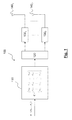
- the Fig. 1 schematically represents a MIMO 100 transmission system with STBC encoding.
- a block of information symbols ⁇ ( ⁇ 1 , ..., ⁇ b ), for example a binary word of b bits or more generally of b M -ary symbols, is encoded into a spatio-temporal matrix:
- VS vs 1 , 1 vs 1 , 2 ... vs 1 , P vs 2 , 1 vs 2 , 2 ... vs 2 , P ⁇ ⁇ ⁇ ⁇ vs T , 1 vs T , 2 ...
- a spatio-temporal code is said to be real if the coefficients c t , p are real, it is said to be linear if the coding function which at any block of information symbols ⁇ associates the spatio-temporal matrix C is linear.
- a 110 spatio-temporal encoder has been designated.
- the encoder provides the multiplexer 120 t th row vector of matrix C.
- the multiplexer transmits to the modulators 130 1 , ..., 130 P the coefficients of the line vector and the modulated signals are transmitted by the antennas 140 1 ,..., 140 P.
- the spatio-temporal code is characterized by its bit rate, that is to say by the number of information symbols that it transmits per channel utilization time (PCU).
- the code is said to be full rate if it is P times higher than the relative bit rate for single-antenna use (SISO).
- SISO single-antenna use
- a code is said unit rate if it is identical to that relating to a single-antenna use.
- the spatio-temporal code is further characterized by its diversity which can be defined as the rank of the matrix C. Maximum diversity will be obtained if for any two code words C 1 and C 2 corresponding to two vectors S 1 and S 2 , the C 1 -C 2 matrix is of full rank.
- the spatio-temporal code is finally characterized by its coding gain which translates the minimum distance between different words of the code. It can be defined as: min VS 1 ⁇ VS 2 ⁇ det ⁇ VS 1 - VS 2 H ⁇ VS 1 - VS 2 or, equivalently, for a linear code: min VS ⁇ 0 ⁇ det VS H ⁇ VS where det ( C ) means the determinant of C and C H is the transposed conjugated matrix of C. For transmission energy per information symbol, the coding gain is bounded. A spatio-temporal code will be more resistant to fading than its coding gain will be high.
- the decoding of the STBC codes is done in a coherent manner, which generally assumes to perform a channel estimation on reception, that is to say to determine the matrix H of the complex propagation coefficients between the antennas. emission and receiving antennas.
- This channel estimation is made possible by sending pilot symbol sequences by the transmission system, thereby reducing the average payload of the information symbol blocks.
- this estimation must be made frequently in the case of a transmission channel with a low signal-to-noise ratio or rapid fluctuations.
- the matrix of the spatio-temporal differential code for a given block depends not only on the information symbols of that block but also on the matrix of the spatio-temporal code for the previous block.
- a delay loop 225 has been included to symbolize the recurrence (4).
- the delay element 225 stores the line vectors to supply the matrix C k-1 during the coding of the block ⁇ k .
- the multiplexer 220 transmits to the modulators 230 1 , 230 2 the coefficients of the line vector.
- the signals thus modulated are transmitted by the antennas 240 2 , 240 2 .
- UWB telecommunication systems which are being approached for the development of future wireless personal networks (WPAN). These systems have the specificity of working directly in baseband with very broadband signals.
- a UWB signal is generally understood to mean a signal conforming to the spectral mask stipulated in the FCC regulation of 14 February 2002 and revised in March 2005, that is to say essentially a signal in the 3.1 to 10.6 GHz spectral band and having a bandwidth of at least 500 MHz at -10dB.
- MB-OFDM OFDM multi-band signals
- UWB signals of impulse type we will only be interested in them later.
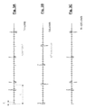
- a UWB pulse signal consists of very short pulses, typically of the order of a few hundred picoseconds, distributed within a frame.
- a separate Time Hopping (TH) code is assigned to each user.
- the duration of the elementary pulse is chosen to be less than the chip duration, ie T w ⁇ T c .
- the time hopping sequences are chosen so as to minimize the number of collisions between pulses belonging to time jump sequences of different users.
- the information symbols may be transmitted by means of amplitude modulation (PAM).
- PAM amplitude modulation
- M ' is the symbol M ' -ary of the PAM modulation.
- the PPM and PAM modulations can also be combined into a composite M.M.
- DS-UWB Direct Spread UWB
- n 0, .., N s -1 is the spreading sequence of the user k .
- the expression (11) is analogous to that of a conventional DS-CDMA signal. It differs however in that the chips do not occupy the entire frame but are distributed in the period T s .
- Fig. 3B a DS-UWB signal associated with a user k .
- the information symbols can be transmitted by means of PPM modulation.
- a modulation M -PPM- M ' -PAM as in (10).
- each antenna transmits a UWB signal modulated according to an information symbol or a block of such symbols (STBC).
- STBC information symbol or a block of such symbols
- ⁇ k ( ⁇ k, 1 , ⁇ k, 2 )
- ⁇ k, 1 s k , 1 v (d k, 1 )
- ⁇ k, 2 s k , v 2 (d k, 2)
- ⁇ is the Dirac symbol.
- the elements of the spatio-temporal code (15) are symbols whose respective amplitudes are given by the recurrence relation (16), and their respective positions PPM by the recurrence relation (17).
- the sign reversals appearing in the matrices (18) have the consequence that the elements of the Spatiotemporal code may have negative amplitudes and therefore do not belong to the M- PPM alphabet.
- the UWB signals modulated by the space-time code contain signed pulses. Given the very short duration of these pulses and therefore the very wide band of the UWB pulse signals, it is excessively difficult to recover a phase information on reception, and in particular to detect a sign reversal.
- some MIMO systems do not lend themselves to the transmission of signed pulses. For example, optical UWB MIMO systems only transmit TH-UWB light intensity signals, which are necessarily devoid of sign information.
- the object of the present invention is therefore to propose a differential space-time code for a MIMO system using pulse UWB signals not involving the transmission of signed pulses.
- a subsidiary object of the present invention is to propose a UWB MIMO transmission system using said space-time code, as well as an associated reception system.
- the radiative elements of the transmission system are UWB antennas.
- the radiative elements of the transmission system are laser diodes or light-emitting diodes.
- the said pulse signal may be a TH-UWB signal, a DS-UWB signal, or a TH-DS-UWB signal.
- the sensors are UWB antennas.
- the sensors are photodetectors.
- the idea underlying the invention is to design a differential space-time code whose coding diversity is obtained thanks to a permutation operator acting on the information symbol modulation positions belonging to a 2-PPM alphabet. , also says binary PPM.
- S k is a matrix of size 2 P ⁇ 2 P depending only on the information symbols
- u 1 (1 1)
- ⁇ is the product of Kronecker
- Min (X) is a matrix whose elements give the values lower two consecutive elements of a row of the matrix X , ie if X is a size matrix P ⁇ 2 P Min (X) is defined by the P ⁇ P size matrix whose
- c k, 1 c k
- P (1 0).
- other values of c k, 1 , ... c k, P can also be envisaged.
- the matrix C k is of the form (19), (20) or (21) and S k is respectively of the form (25), (26) or (27), then the matrix C k + 1 obtained by the recurrence relation (21) is still of the form (19), (20) or (21).
- the matrix C k given by (23) consists of 0 and of 1.
- the spatio-temporal differential code C k does not introduce a reversal of the polarity of the pulses of the modulated signal, nor of their amplification. .
- the space-time code C k is at unit rate since P information symbols are transmitted during P uses of the channel. We can also show that it is at maximum diversity.
- any permutation on the lines (here understood by line, a line of 1 ⁇ 2 vectors) and / or the columns of C k in the expressions (19), (20), (21) is a spatio code -Temporal according to the invention, a permutation on the lines equivalent to a permutation of the times of use of the channel (PCUs) and a permutation on the columns equivalent to a permutation of the transmission antennas.
- c k, 2.1 and c k , 2.2 correspond to the respective amplitudes of the pulses at first and second modulation positions for the first symbol time of the k th block time and for the second antenna.
- the first antenna successively transmits pulses of respective amplitudes c k , 2 , 2 and c k , 2.1 for the first and second modulation positions, then that the second antenna transmits successively during this same time pulses of respective amplitudes c k , 1.1 and c k , 1.2 for these same modulation positions.
- c k, 1,1, c k, 1,2, c k, c k and 2.1, 2.2 are values equal to 0 or 1 and introduced by therefore no polarity reversal or pulse amplification.
- This space-time code lends itself well to the modulation of an ultra-wideband signal.
- the Fig. 5 represents a multi-antenna transmission system using a differential space-time code according to one embodiment of the invention.
- P 2 and the spatio-temporal code is given by (19).
- the system 500 can generally receive 2-bit words, the value of a bit giving a position PPM, for example 0 corresponds to the first position PPM and 1 corresponds to the second.
- the block of information symbols ⁇ k (s k, 1 , s k, 2 ) undergoes a coding operation in the differential space-time coder 510. More precisely, the coder 510 first determines the elements of the matrix S k by means of (25), then calculates the matrix C k from S k and C k-1 by means of the recurrence relation (23). The coefficients of the matrix C k-1 are stored in the delay element 525 to be available when coding the block ⁇ k .
- the 2 line 1 ⁇ 2 vectors of the first line of C k that is ( c k , 1.1 c k, 1.2 ), ( c k, 2.1 c k , 2.2 ) are respectively transmitted to the modulators UWB 530 1 and 530 2 via the multiplexer 520 to generate the first frame according to (29) and (30), then the 2 line 1 ⁇ 2 vectors of the first line of C k , of the second line of C k , that is ( c k, 2.2 c k, 2.1 ), ( c k, 1.1 c k, 1.2 ) to generate the second frames according to (31) and (32).
- the pulsed UWB signals thus modulated are then transmitted to the radiating elements 540 1 and 540 2 .
- These radiative elements may be UWB antennas or laser diodes or light-emitting diodes, operating for example in the infrared range, associated with electro-optical modulators.
- the UWB signals transmitted by the system illustrated in Fig. 5 can be processed by a single-antenna or multi-antenna receiver according to the invention which will now be described in connection with the Figure 6 .
- the receiver 600 comprises Q sensors 610, for example Q photoreceptors, or as shown here Q UWB receiving antennas.
- Each antenna (or sensor) is connected to a L-shaped 620 Rake filter to track the multi-path L of the propagation channel relating to that antenna.
- Y k is the transpose of Y k and S k is defined by (25), (26) or (27) according to the value of P.
- the Fig. 7A gives the binary error rate (BER) curves as a function of the signal-to-noise ratio (SNR) for a UWB MIMO system using the spatio-temporal coding according to the invention with a propagation channel that does not introduce any interference between pulses.
- the separation between the two PMM positions is 100 ns, chosen larger than the UWB channel time delay (less than 100ns).
- the error rate curves for a MISO system with two transmit antennas (2 ⁇ 1), 720, and for a MISO system with four transmit antennas (4 ⁇ 1), 730 are shown. comparison is also shown in 710 the error rate curve for a conventional single-antenna system (1 ⁇ 1). In both cases, the gain in BER will be noted with respect to the conventional mono-antenna system.
- the Fig. 7B gives the bit error rate (BER) curves as a function of the signal-to-noise ratio (SNR) for a UWB MIMO system using the spatio-temporal coding according to the invention with a transmission channel. propagation introducing interference between pulses.
- the separation between the two PMM positions is 5 ns, less than the time delay of the UWB channel (less than 100ns).
- the error rate curve for a conventional single-antenna system (1 ⁇ 1) was also included in 715. It will be noted that in this case also a gain in BER is obtained with respect to the conventional mono-antenna system.
Landscapes
- Engineering & Computer Science (AREA)
- Computer Networks & Wireless Communication (AREA)
- Signal Processing (AREA)
- Physics & Mathematics (AREA)
- Spectroscopy & Molecular Physics (AREA)
- Radio Transmission System (AREA)
- Dc Digital Transmission (AREA)
- Mobile Radio Communication Systems (AREA)
Applications Claiming Priority (1)
| Application Number | Priority Date | Filing Date | Title |
|---|---|---|---|
| FR0851400A FR2928509B1 (fr) | 2008-03-04 | 2008-03-04 | Procede de codage spatio-temporel differentiel. |
Publications (2)
| Publication Number | Publication Date |
|---|---|
| EP2099137A2 true EP2099137A2 (de) | 2009-09-09 |
| EP2099137A3 EP2099137A3 (de) | 2015-07-01 |
Family
ID=40029178
Family Applications (1)
| Application Number | Title | Priority Date | Filing Date |
|---|---|---|---|
| EP09153838.9A Withdrawn EP2099137A3 (de) | 2008-03-04 | 2009-02-27 | Differentielles Raum-Zeit-Kodierverfahren |
Country Status (6)
| Country | Link |
|---|---|
| US (1) | US8194775B2 (de) |
| EP (1) | EP2099137A3 (de) |
| JP (1) | JP2009232453A (de) |
| KR (1) | KR20090095490A (de) |
| CN (1) | CN101527619B (de) |
| FR (1) | FR2928509B1 (de) |
Cited By (1)
| Publication number | Priority date | Publication date | Assignee | Title |
|---|---|---|---|---|
| CN102064915A (zh) * | 2010-12-15 | 2011-05-18 | 西安交通大学 | 一种适合快衰落信道的分布式差分空时编码传输方法 |
Families Citing this family (10)
| Publication number | Priority date | Publication date | Assignee | Title |
|---|---|---|---|---|
| FR2927205A1 (fr) * | 2008-01-31 | 2009-08-07 | Commissariat Energie Atomique | Procede de codage spatio-temporel a faible papr pour systeme de communication multi-antenne de type uwb impulsionnel |
| JP5191971B2 (ja) | 2009-10-06 | 2013-05-08 | ジヤトコ株式会社 | 車両のオイルポンプ制御装置 |
| US9319105B2 (en) * | 2010-06-29 | 2016-04-19 | Lattice Semiconductor Corporation | Methods and systems for near-field MIMO communications |
| WO2013129422A1 (ja) * | 2012-03-02 | 2013-09-06 | 三菱電機株式会社 | 無線送信装置、無線受信装置およびデータ伝送方法 |
| US9716568B2 (en) * | 2013-09-26 | 2017-07-25 | Hitachi Kokusai Electric Inc. | Wireless communication system and transmitter |
| CN107659520B (zh) * | 2016-07-25 | 2021-07-02 | 苏州氶颂展览展示有限公司 | 一种信号调制方法和装置 |
| CN107894204B (zh) | 2016-10-04 | 2020-02-21 | 财团法人工业技术研究院 | 干涉仪及其成像方法 |
| US11218252B2 (en) * | 2017-06-15 | 2022-01-04 | Mitsubishi Electric Corporation | Transmission device, receiving device, and wireless communication system |
| JP7341980B2 (ja) * | 2017-08-15 | 2023-09-11 | フラウンホッファー-ゲゼルシャフト ツァ フェルダールング デァ アンゲヴァンテン フォアシュンク エー.ファオ | 無線ネットワークおよび装置 |
| CN109995404B (zh) * | 2018-12-17 | 2021-06-01 | 郑州大学 | 空频域调制的一种差分调制和解调方法 |
-
2008
- 2008-03-04 FR FR0851400A patent/FR2928509B1/fr not_active Expired - Fee Related
-
2009
- 2009-02-26 US US12/393,594 patent/US8194775B2/en not_active Expired - Fee Related
- 2009-02-27 EP EP09153838.9A patent/EP2099137A3/de not_active Withdrawn
- 2009-03-03 KR KR1020090018140A patent/KR20090095490A/ko not_active Abandoned
- 2009-03-04 JP JP2009050382A patent/JP2009232453A/ja active Pending
- 2009-03-04 CN CN200910134688.1A patent/CN101527619B/zh not_active Expired - Fee Related
Non-Patent Citations (3)
| Title |
|---|
| C. ABOU-RJEILY ET AL.: "Differential space-time ultra- wideband communications", PROC. OF IEEE CONFERENCE ON ULTRA-WIDE BAND, September 2005 (2005-09-01), pages 248 - 253 |
| C. GAO ET AL.: "Bit error probability for space-time block code with coherent and differential detection", PROC. OF VEHICULAR TECHNOLOGY CONFERENCE, vol. 1, September 2002 (2002-09-01), pages 410 - 414 |
| V. TAROKH ET AL.: "A differential detection scheme for transmit diversity", IEEE JOURNAL ON SELECTED AREAS IN COMMUNICATIONS, vol. 18, no. 7, July 2000 (2000-07-01), pages 1169 - 1174 |
Cited By (2)
| Publication number | Priority date | Publication date | Assignee | Title |
|---|---|---|---|---|
| CN102064915A (zh) * | 2010-12-15 | 2011-05-18 | 西安交通大学 | 一种适合快衰落信道的分布式差分空时编码传输方法 |
| CN102064915B (zh) * | 2010-12-15 | 2013-05-22 | 西安交通大学 | 一种适合快衰落信道的分布式差分空时编码传输方法 |
Also Published As
| Publication number | Publication date |
|---|---|
| US8194775B2 (en) | 2012-06-05 |
| US20090225809A1 (en) | 2009-09-10 |
| EP2099137A3 (de) | 2015-07-01 |
| JP2009232453A (ja) | 2009-10-08 |
| FR2928509A1 (fr) | 2009-09-11 |
| FR2928509B1 (fr) | 2011-01-14 |
| CN101527619A (zh) | 2009-09-09 |
| CN101527619B (zh) | 2014-06-11 |
| KR20090095490A (ko) | 2009-09-09 |
Similar Documents
| Publication | Publication Date | Title |
|---|---|---|
| EP2099137A2 (de) | Differentielles Raum-Zeit-Kodierverfahren | |
| EP2245751B1 (de) | Verfahren zur räumlich-zeitlichen codierung mit niedrigen papr für ein mehrantennen-kommunikationssystem des impuls-uwb-typs | |
| EP2005608B1 (de) | Verfahren zur räumlich-zeitlichen codierung für ein zweiantennen-kommunikationssystem des gepulsten uwb-typs | |
| EP2026475A1 (de) | Raum-Zeit-Kodier-/Dekodierverfahren für Mehrfachantennen-Kommunikationssystem vom Impulstyp | |
| EP1865613B1 (de) | UWB kooperatives kohärentes Nachrichtentechniksystem | |
| EP1690361B1 (de) | Verfahren zur mehrantennenübertragung eines linear vorcodierten signals, entsprechende einrichtungen, signal und empfangsverfahren | |
| EP1981203B1 (de) | Mehrfachantenneneinrichtung und Verfahren zur Übertragung von Signalen | |
| EP2070199A1 (de) | Verfahren zur räumlichen und zeitlichen kodierung für eine mehrantennen-kommunikationsvorrichtung mit uwb-impulsen | |
| WO2008040716A1 (fr) | Procédé de codage spatio-temporel pour système de communication multi-antenne de type uwb impulsionnel | |
| EP1852980B1 (de) | Kooperatives, inkohärentes UWB-Kommunikationssystem | |
| EP2122892B1 (de) | Verfahren zur raum-zeit-kodierung für ein kommunikationssystem mit mehreren antennen und welches ultrabreitbandpulse verwendet | |
| EP1738513B1 (de) | Verfahren zum senden eines signals in einem mehrantennensystem sowie entsprechendes sendesignal und kanalschätzungsverfahren | |
| WO2005034386A1 (fr) | Procede d'emission multi-antennes d'un signal par codes espace-temps en bloc, procede de reception et signal correspondant | |
| US7864876B2 (en) | Differential space-time block coding apparatus using eight or less transmit antennas | |
| EP1995883A1 (de) | MIMO-UWB-Kommunikationssystem vom inkohärenten Typ | |
| EP2053814B1 (de) | Verfahren zur Raum-Zeit-Kodierung mittels eines gespaltenen Position-Modulation-Alphabets | |
| FR2927207A1 (fr) | Systeme mimo optique |
Legal Events
| Date | Code | Title | Description |
|---|---|---|---|
| PUAI | Public reference made under article 153(3) epc to a published international application that has entered the european phase |
Free format text: ORIGINAL CODE: 0009012 |
|
| AK | Designated contracting states |
Kind code of ref document: A2 Designated state(s): AT BE BG CH CY CZ DE DK EE ES FI FR GB GR HR HU IE IS IT LI LT LU LV MC MK MT NL NO PL PT RO SE SI SK TR |
|
| AX | Request for extension of the european patent |
Extension state: AL BA RS |
|
| RAP1 | Party data changed (applicant data changed or rights of an application transferred) |
Owner name: COMMISSARIAT A L'ENERGIE ATOMIQUE ET AUX ENERGIES |
|
| PUAL | Search report despatched |
Free format text: ORIGINAL CODE: 0009013 |
|
| AK | Designated contracting states |
Kind code of ref document: A3 Designated state(s): AT BE BG CH CY CZ DE DK EE ES FI FR GB GR HR HU IE IS IT LI LT LU LV MC MK MT NL NO PL PT RO SE SI SK TR |
|
| AX | Request for extension of the european patent |
Extension state: AL BA RS |
|
| RIC1 | Information provided on ipc code assigned before grant |
Ipc: H04B 1/69 20110101AFI20150526BHEP Ipc: H04L 1/06 20060101ALI20150526BHEP Ipc: H04L 25/49 20060101ALI20150526BHEP |
|
| AKY | No designation fees paid | ||
| AXX | Extension fees paid |
Extension state: AL Extension state: RS Extension state: BA |
|
| REG | Reference to a national code |
Ref country code: DE Ref legal event code: R108 |
|
| STAA | Information on the status of an ep patent application or granted ep patent |
Free format text: STATUS: THE APPLICATION IS DEEMED TO BE WITHDRAWN |
|
| 18D | Application deemed to be withdrawn |
Effective date: 20160105 |