EP2099142B1 - Verfahren zur Herstellung von Funkverbindungen über einen Mehrfachstrahl-Satelliten - Google Patents
Verfahren zur Herstellung von Funkverbindungen über einen Mehrfachstrahl-Satelliten Download PDFInfo
- Publication number
- EP2099142B1 EP2099142B1 EP09305186A EP09305186A EP2099142B1 EP 2099142 B1 EP2099142 B1 EP 2099142B1 EP 09305186 A EP09305186 A EP 09305186A EP 09305186 A EP09305186 A EP 09305186A EP 2099142 B1 EP2099142 B1 EP 2099142B1
- Authority
- EP
- European Patent Office
- Prior art keywords
- cell
- satellite
- beams
- terrestrial
- spot
- Prior art date
- Legal status (The legal status is an assumption and is not a legal conclusion. Google has not performed a legal analysis and makes no representation as to the accuracy of the status listed.)
- Not-in-force
Links
- 238000000034 method Methods 0.000 title claims description 43
- 230000010287 polarization Effects 0.000 claims description 40
- 230000001174 ascending effect Effects 0.000 claims 2
- 230000002950 deficient Effects 0.000 description 24
- 239000003086 colorant Substances 0.000 description 7
- 230000005540 biological transmission Effects 0.000 description 6
- 238000001228 spectrum Methods 0.000 description 5
- 230000001965 increasing effect Effects 0.000 description 3
- 230000002441 reversible effect Effects 0.000 description 3
- KRQUFUKTQHISJB-YYADALCUSA-N 2-[(E)-N-[2-(4-chlorophenoxy)propoxy]-C-propylcarbonimidoyl]-3-hydroxy-5-(thian-3-yl)cyclohex-2-en-1-one Chemical compound CCC\C(=N/OCC(C)OC1=CC=C(Cl)C=C1)C1=C(O)CC(CC1=O)C1CCCSC1 KRQUFUKTQHISJB-YYADALCUSA-N 0.000 description 2
- 230000008859 change Effects 0.000 description 2
- JEIPFZHSYJVQDO-UHFFFAOYSA-N iron(III) oxide Inorganic materials O=[Fe]O[Fe]=O JEIPFZHSYJVQDO-UHFFFAOYSA-N 0.000 description 2
- 230000000630 rising effect Effects 0.000 description 2
- 230000002457 bidirectional effect Effects 0.000 description 1
- 230000033228 biological regulation Effects 0.000 description 1
- 238000004891 communication Methods 0.000 description 1
- 238000010276 construction Methods 0.000 description 1
- 238000010586 diagram Methods 0.000 description 1
- 238000001914 filtration Methods 0.000 description 1
- 230000001939 inductive effect Effects 0.000 description 1
- 230000007257 malfunction Effects 0.000 description 1
- 230000004048 modification Effects 0.000 description 1
- 238000012986 modification Methods 0.000 description 1
- 230000000750 progressive effect Effects 0.000 description 1
- 238000011084 recovery Methods 0.000 description 1
- 230000008521 reorganization Effects 0.000 description 1
- 238000000926 separation method Methods 0.000 description 1
- 230000008054 signal transmission Effects 0.000 description 1
Images




Classifications
-
- H—ELECTRICITY
- H04—ELECTRIC COMMUNICATION TECHNIQUE
- H04B—TRANSMISSION
- H04B7/00—Radio transmission systems, i.e. using radiation field
- H04B7/14—Relay systems
- H04B7/15—Active relay systems
- H04B7/204—Multiple access
- H04B7/2041—Spot beam multiple access
-
- H—ELECTRICITY
- H01—ELECTRIC ELEMENTS
- H01Q—ANTENNAS, i.e. RADIO AERIALS
- H01Q25/00—Antennas or antenna systems providing at least two radiating patterns
-
- H—ELECTRICITY
- H01—ELECTRIC ELEMENTS
- H01Q—ANTENNAS, i.e. RADIO AERIALS
- H01Q3/00—Arrangements for changing or varying the orientation or the shape of the directional pattern of the waves radiated from an antenna or antenna system
- H01Q3/26—Arrangements for changing or varying the orientation or the shape of the directional pattern of the waves radiated from an antenna or antenna system varying the relative phase or relative amplitude of energisation between two or more active radiating elements; varying the distribution of energy across a radiating aperture
-
- H—ELECTRICITY
- H01—ELECTRIC ELEMENTS
- H01Q—ANTENNAS, i.e. RADIO AERIALS
- H01Q3/00—Arrangements for changing or varying the orientation or the shape of the directional pattern of the waves radiated from an antenna or antenna system
- H01Q3/26—Arrangements for changing or varying the orientation or the shape of the directional pattern of the waves radiated from an antenna or antenna system varying the relative phase or relative amplitude of energisation between two or more active radiating elements; varying the distribution of energy across a radiating aperture
- H01Q3/30—Arrangements for changing or varying the orientation or the shape of the directional pattern of the waves radiated from an antenna or antenna system varying the relative phase or relative amplitude of energisation between two or more active radiating elements; varying the distribution of energy across a radiating aperture varying the relative phase between the radiating elements of an array
Definitions
- the present invention relates to a method for establishing radio frequency links via a multi-beam or multispots telecommunication satellite, between at least one terrestrial station and a service area composed of a plurality of elementary coverage areas, called cells, each cell having a plurality of terrestrial terminals.
- This type of satellite allows the use of several antenna beams on board the satellite to cover contiguous geographical areas or cells, instead of a single wide beam.
- Such multibeam satellites make it possible to establish several radio frequency links occupying the same frequency band on different beams.
- a broadcasting-satellite service may be considered equivalent to the forward path of a bidirectional system as described above.
- FIG. 1 An example of a forward path in a multibeam configuration is illustrated in figure 1 .
- Signals are sent to a multibeam satellite 3 on an uplink LM by a terrestrial station 2 such as a gateway in English connected to an Internet backbone 5. These signals are then processed at the satellite 3 then retransmitted on a downlink LD in the form of a plurality of beams or spots forming zones of elementary covers or C1 to C8 cells in which terrestrial terminals 6 are located. Each cell C1 to C8 is associated with a beam SP1 to SP8. It will be noted that, in the case of configuration 1, the eight cells C1 to C8 associated with the eight beams SP1 to SP8, respectively, form a group of cells served by the same earth station 2. The return path of the terrestrial terminals 6 to the earth station 2 functions identically with a reverse communication direction.
- the band Ka for the region 1 (Europe, Africa, Middle East ) is defined in Table 1 below: Table 1.
- Way to go Uplink (from the ground station) 27.5 GHz to 29.5 GHz Downlink (to land terminals) 19.7 GHz to 20.2 GHz
- Way back Uplink (terrestrial terminals) 29.5 GHz to 30.0 GHz
- Downlink (to the land station) 17.7 GHz to 19.7 GHz
- a service area to be covered is formed by a plurality of contiguous cells (zones of elementary covers), a beam being associated with each cell.
- a homogeneous multi-beam coverage area SA is represented in figure 2a ), each cell being represented by a hexagon FH so that the coverage area is composed of a plurality of hexagons FH in which ⁇ cell is the external dimension of the cell expressed by the satellite angle associated with the coverage.
- the antenna beam associated with each cell is not capable of producing a hexagonal shape, a good approximation consisting in considering a plurality of circular beams FC as represented in FIG. figure 2b ).
- the association of a beam with a cell is done by taking into account the best performance of the satellite for said beam, in particular in terms of EIRP (Equivalent Radiated Isotropic Power) and merit factor G / T (ratio gain over temperature of noise):
- EIRP Equivalent Radiated Isotropic Power
- G / T ratio gain over temperature of noise
- Configuration 1 as represented in figure 1 uses a technique known as frequency reuse: this technique makes it possible to use the same frequency range several times in the same satellite system in order to increase the total capacity of the system without increasing the allocated bandwidth.
- Frequency reuse schemes called color schemes, are known that map a color to each of the satellite beams. These color schemes are used to describe the assignment of a plurality of frequency bands to the satellite beams for radio frequency transmissions to be performed in each of these beams. In these diagrams, each color corresponds to one of these frequency bands.
- the polarization can be linear (in this case the two directions of polarization are respectively horizontal and vertical) or circular (in this case the two directions of polarization are respectively circular left or circular right).
- the uplink from station 2 uses two polarizations with four channels for each polarization, respectively Ch1 to Ch4 for the first polarization and Ch5 to Ch8 for the second polarization: the use of two polarizations makes it possible to reduce the total number of stations land.
- the eight channels Ch1 to Ch8, after treatment by the payload of the satellite 3 will form the eight beams SP1 to SP8 (a channel being associated with a beam in this example).
- each color is associated at a band of 250 MHz and a direction of polarization.
- a color is thus associated with each beam of the satellite (and therefore a cell) so that the beams of the same "color" are non-adjacent: the contiguous cells therefore correspond to different colors.
- the figures 3 a) and 3 b) take the example of Figures 2 a) and 2 b ) with a four-color scheme.
- the figure 3 a) illustrates a homogeneous multibeam coverage area, each cell being represented by a hexagon associated with a color so that the contiguous cells thus correspond to different colors.
- the Figure 3 (b) represents the circular beams associated with each cell (whose color is identical to that of the associated cell).
- FIG. 4 An example of a four-color scheme for the coverage of Europe is represented in figure 4 . In this case, 80 cells are needed to cover Europe. This scheme allows for European coverage to and from terminals using a 500 MHz spectrum but with frequency reuse. Coverage for land stations is less restrictive and can be provided by a subset of beams or a separate cover.
- This type of scheme is applicable for both uplink and downlink.
- the creation of a beam is made from a horn radiating towards a reflector.
- a reflector may be associated with a color so that four-color coverage is provided by four reflectors.
- the figure 5 illustrates a frequency plan broken down into an uplink PMVA uplink frequency plan, a forward path PDVA downlink frequency plan, a PMVR uplink frequency plan on the return channel and a frequency plan downlink PDVR on the return path.
- the notation RHC and LHC respectively denote the right and left circular polarization directions.
- the PMVA plane corresponding to the uplink on the forward path has 2 GHz spectrum available in frequency so that 16 channels of 250 MHz bandwidth are generated by a terrestrial station (8 channels for each polarization). These 16 channels, after processing by the payload of the satellite will form 16 beams. In this example, 16 beams (and therefore 16 cells) are generated by a ground station.
- the polarizations are reversed so that the red and yellow colors have left circular polarization and the blue and green colors have a right circular polarization.
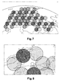
- the figure 7 illustrates this phenomenon in case of failure of a terrestrial station serving 16 beams for the coverage of the Europe zone as represented in figure 4 .
- the loss of the station corresponds to the loss of one-fifth (loss of 16 beams out of 80) of the overall coverage, the commercial impact of such a change in coverage being, of course, considerable.
- the figure 8 represents an enlargement of the same area in Great Britain: we can see that the densely populated area around London is no longer covered.
- the document EP0812072 discloses a method of reconfiguring the payload of a multibeam satellite according to failures in said load.
- the present invention aims at providing a method for establishing radio frequency links via a multibeam satellite between at least one terrestrial station and a service area composed of a plurality of cells, said method making it possible to improve the coverage by case of loss of one or a plurality of beams.
- the invention proposes a method for establishing radio frequency links via a multi-beam satellite, said multibeam satellite, between at least one terrestrial station and a service area composed of a plurality of elementary coverage areas.
- said cells each cell comprising a plurality of terrestrial terminals and being associated with a beam to which a frequency band is assigned, said method being characterized in that in the event of loss of a beam associated with a cell, said faulty cell , the beam associated with at least one cell contiguous to said faulty cell is also associated with a part of said faulty cell.
- one “enlarges” at least one cell contiguous to the defective cell; in other words, the beam associated with this contiguous cell is used to cover part of the surface of the faulty cell by using the beam performance outside its own cell.
- the reference cell in which there is a terrestrial terminal can no longer function, it is indeed possible to connect this terminal to another beam by "extending the cell associated with this beam.
- a part of the terrestrial terminals initially belonging to the defective cell is found in an adjoining "enlarged cell whose associated beam covers not only the contiguous cell but also a part of the defective cell.
- the gain of this new beam is lower than that of the lost reference beam, the G / T and the EIRP of the satellite offered by the new beam being lower, but the method according to the invention provides a backup solution in degraded mode limiting the loss of coverage of the service area due to the lost beam.
- the beam covers not only the cell to which it is initially associated but also the part of the faulty cell without modifying the size of said beam: it is indeed the size of the contiguous cell which is enlarged via the partial association from his beam to the faulty cell. This is made possible by the fact that the beams, assimilated to circular spots, do not stop at the edge of the generally hexagonal cell with which they are associated.
- the method according to the invention applies equally to an uplink from the cells comprising terrestrial terminals to the satellite (return channel) and to a downlink from the satellite to the cells comprising terrestrial terminals (channel to go). It should also be mentioned that the method according to the invention applies without modification on board the satellite: the beams remain the same and advantageously the overflow of beams on cells contiguous to the cells with which they are associated.
- each of said parts contributes to an equal area of coverage.
- At least two of said parts contribute to a different surface area of coverage.
- each beam has a given rising or falling frequency band and a given direction of polarization, the beams having the same frequency band and the same direction of polarization being non-adjacent.
- said rising or falling frequency bands belong to one of the following bands: Ka, Ku.
- the terrestrial terminals of said faulty cell are able to transmit and / or receive signals in both directions of polarization so that all the beams associated with the cells contiguous to said faulty cell can be associated with a part of said faulty cell.
- the direction of the transmission and reception polarization is, in general, opposite.
- the terrestrial terminals of said faulty cell are able to transmit and / or receive signals in a single direction of polarization so that only the beams associated with the cells contiguous to said faulty cell and having the same sense of direction. polarization that the faulty beam can be associated with a portion of said faulty cell.
- said radiofrequency links are established between a plurality of earth stations and said service area so that, for a first beam assigned to a first earth station, all the beams adjacent to said first beam are each assigned to a land station different from said first land station.
- the figure 6 resumes the illustration of the Figure 3 (b) in case of loss of yellow beams.
- loss of yellow beams Such a situation may for example occur in the event of failure of the satellite antenna reflector in charge of the generation of yellow beams. This type of failure causes the loss of a quarter of the beams.
- the CPJ lost cells associated with the yellow beams are each surrounded by six contiguous cells, none of which is a cell associated with a yellow beam (two cells associated with a green beam, two cells associated with a yellow beam). a blue beam and two cells associated with a red beam).
- the method according to the invention makes it possible to reduce the loss of coverage generated by these lost cells.
- FIGS 9 (a) and 9 (b) A first embodiment of the method according to the invention is illustrated in Figures 9 (a) and 9 (b) .
- an antenna beam associated with a cell is not capable of producing a hexagonal shape, a good approximation of considering a circular beam.
- a cell is determined as the portion of the service area associated with the beam providing the highest gain on that area among all the beams of the satellite.
- the beams do not stop at the edges of the cell: the method according to the invention advantageously uses the overflow of each beam on the cells contiguous to the cell with which it is associated.
- all the yellow beams are defective so that the cells associated with the yellow beams are not covered: these cells are called defective cells.
- the cells contiguous to the defective cells are enlarged.
- the beams of the same "color" being non-adjacent, the contiguous cells therefore correspond to different colors.
- By enlargement of a contiguous cell is meant associating the beam associated with this contiguous cell with a part of the surface of the defective cell.
- the six beams (two red FR1 and FR2, two blue FB1 and FB2 and two green FV1 and FV2) respectively associated with the 6 cells CR1, CR2, CB1, CB2, CV1 and CV2 contiguous to the defective cell are each associated with a portion of the surface of the hexagonal cell so the uncovered surface CPJ 'is well below the surface of the defective CPJ cell as shown in FIG.
- the beams FR1, FR2, FB1, FB2, FV1 and FV2 also continue to be associated respectively with the CR1, CR2, CB1, CB2, CV1 and CV2 cells.
- the size of the beams FR1, FR2, FB1, FB2, FV1 and FV2 does not increase, the magnification of the beams represented in FIG. figure 9 a) (ie the two concentric circles, one dashed and the other solid line, respectively showing the beam used in operating mode according to the prior art and the beam in operating mode according to the method according to the invention) only to illustrate the fact that these are associated to a larger surface: the size of the beams remains the same.
- the frequency bands allocated to the beams remain the same: there is no reorganization of the frequency bands but in the defective cell the frequency bands and the polarizations are defined according to the sectors (geographical) and the extension. beams (ie the terminals located in the defective cell transmit and receive in the frequency band associated with the new enlarged cell in which they are located but this does not imply any change of infrastructure).
- the method according to the invention provides a solution in intermediate degraded mode between the optimal solution with all the cells in operation and the solution with loss of beams without partial recovery of service area.
- Another way of describing the invention is to consider that some of the terrestrial terminals initially in the defective cell are reassigned to the cells contiguous to the defective cell.
- the terrestrial terminal T1 which originally belonged to the faulty cell belongs to the cell CV1: the cell CV1 is "enlarged” (ie the radiofrequency link is on the beam FV1) to cover the area to which originally belonged to the T1 terminal.
- the terrestrial terminal T2 which initially belonged to the defective cell belongs to the cell CV2: the cell CV2 is "enlarged” (ie the radiofrequency link is made on the beam FV2) to make it possible to cover the zone to which originally belonged the terminal T2.
- the figure 9 b) represents the service area covered by the method according to this first embodiment of the invention using the extension of all the cells contiguous to the defective cell.
- the figure 10 b) represents the service area covered by the method according to this second embodiment of the invention using the extension of the cells contiguous to the defective cell and having a polarization in the same direction as the defective cell.
- the method according to the invention applies equally to an uplink from cells comprising terrestrial terminals to the satellite (return channel) and to a downlink from the satellite to the cells comprising terrestrial terminals (forward channel).
- the four-color scheme is symmetrical between the forward and return channels.
- a cell is the same color in reception and transmission.
- this color does not correspond to the same frequency in the forward channel (reception of the signal transmitted by the satellite between 19.7 and 20.2 GHz) and in return channel (emission towards the satellite between 29.5 and 30.0 GHz).
- the polarization is reversed between the transmitted signal and the received signal, which allows the use of simpler and less expensive terminals, the separation between transmitted signal and received signal being polarized and not requiring specific filtering.
- the parts of the defective cell reallocated to another adjacent beam as well as on the Figures 9 (a) and 9 (b) than on the Figures 10 (a) and 10 (b) , have the same surface.
- the figure 11 illustrates this embodiment. It can be seen that the portion P1 associated with the red beam FR1 "has a surface smaller than the area of the portion P2 associated with the red beam FR2". Such an implementation of the method according to the invention can prove particularly useful when it is desired to recover an operation on a part including a location of interest L.
- the enlargement of the cells implies that the earth stations must manage an extension of the number of terrestrial terminals with which they must communicate. This is possible in the case of a centralized management of MAC ("Media Access Control") or IP ("Internet Protocol”) addresses of the terminals. This centralized management allows all earth stations, almost in real time, to know which terminals are attached to them, and to regain control in the event of a failure.
- Another solution may be to give the terrestrial terminals an address in normal operating mode connecting them to their reference earth station and an "emergency" address (in case of failure of the beam to which they are attached) connecting them to a back-up earth station, the reconfiguration thus becoming very fast.
- the method according to the invention finds a particularly advantageous application in the case of the failure of a terrestrial station involving the loss of all the beams generated from the station (in the example cited above with reference to the state of the technique, 16 bundles were lost).
- the satellite data transmission network is constructed so that for a first beam assigned to a first earth station, all the beams adjacent to said first beam are each assigned to a different ground station of the first station. earthly. In other words, if a beam is "served" by a ground station, the beams surrounding that beam are necessarily served by another earth station.
- Such a configuration makes it possible, in the event of failure of a terrestrial station, to always have the beams adjacent to the lost beam coming from the defective ground station; implementation of the method according to the invention is then always possible since there are always bundles associated with the cells contiguous to the lost cell. It will be noted that such an architecture is particularly original insofar as the beams served by the same earth station are not grouped geographically but instead are voluntarily remote so as to implement the method according to the invention.
- the invention has been more particularly described in the case of a four-color scheme but it can be applied to another number of colors (two for example).
Landscapes
- Engineering & Computer Science (AREA)
- Computer Networks & Wireless Communication (AREA)
- Signal Processing (AREA)
- Radio Relay Systems (AREA)
Claims (9)
- Verfahren zum Herstellen von Hochfrequenzverbindungen über einen Mehrstrahl-Fernmeldesatellit, einen sogenannten Mehrstrahlsatellit, zwischen mindestens einer Bodenstation und einem Dienstbereich, der aus mehreren Grundversorgungsbereichen, sogenannten Zellen, besteht, wobei jede Zelle mehrere Bodenstationen umfasst und einem Strahl zugehörig ist, dem ein Frequenzband zugewiesen ist, wobei im Falle eines Verlusts eines einer Zelle, einer sogenannten ausgefallenen Zelle, zugehörigen Strahls, der mindestens einer an die ausgefallene Zelle angrenzenden Zelle (CR1, CR2, CB1, CB2, CV1, CV2) zugehörige Strahl (FR1, FR2, FB1, FB2, FV1, FV2) auch mit einem Teil der ausgefallenen Zelle verbunden wird, derart, dass die Fläche (CPJ) der ausgefallenen Zelle vermindert wird, wobei die Hochfrequenzverbindungen derart zwischen mehreren Bodenstationen und dem Versorgungsbereich hergestellt werden, dass für einen ersten Strahl, der einer ersten Bodenstation zugeordnet ist, sämtliche dem ersten Strahl benachbarten Strahlen jeweils einer Bodenstation zugeordnet werden, die sich von der ersten Bodenstation unterscheidet.
- Verfahren nach Anspruch 1, dadurch gekennzeichnet, dass mehrere Strahlen (FR1, FR2, FB1, FB2, FV1, FV2), die jeweils einer an die ausgefallene Zelle angrenzenden Zelle (CR1, CR2, CB1, CB2, CV1, CV2) zugehörig sind, jeweils mit einem Teil der ausgefallenen Zelle verbunden werden.
- Verfahren nach Anspruch 2, dadurch gekennzeichnet, dass jeder der Teile zu einer Versorgungsfläche beiträgt.
- Verfahren nach Anspruch 2, dadurch gekennzeichnet, das mindestens zwei der Teile (P1, P2) zu einer unterschiedlichen Versorgungsfläche beitragen.
- Verfahren nach einem der vorhergehenden Ansprüche, dadurch gekennzeichnet, dass jeder Strahl (FR1, FR2, FB1, FB2, FV1, FV2) ein gegebenes Aufwärtsstrecken- oder Abwärtsstreckenfrequenzband und eine gegebene Polarisationsrichtung aufweist, wobei die Strahlen, die ein gleiches Frequenzband und eine gleiche Polarisationsrichtung aufweisen, nicht benachbart sind.
- Verfahren nach dem vorhergehenden Anspruch, dadurch gekennzeichnet, dass die Aufwärtsstrecken- oder Abwärtsstreckenfrequenzbänder zu einem der folgenden Bänder gehören: Ka, Ku.
- Verfahren nach einem der Ansprüche 5 oder 6, dadurch gekennzeichnet, dass die Bodenendgeräte der ausgefallenen Zelle geeignet sind, in beiden Polarisationsrichtungen Signale zu senden und/oder zu empfangen, derart, dass sämtliche Strahlen (FR1, FR2, FB1, FB2, FV1, FV2), die Zellen (CR1, CR2, CB2, CB2, CV1, CV2) zugehörig sind, die an die ausgefallene Zelle angrenzen, mit einem Teil der ausgefallenen Zelle verbunden werden können.
- Verfahren nach einem der Ansprüche 5 oder 6, dadurch gekennzeichnet, dass die Bodenendgeräte der ausgefallenen Zelle geeignet sind, Signale in einer einzigen Polarisationsrichtung zu senden und/oder zu empfangen, derart, dass nur die Strahlen (FR1', FR2'), die den an die ausgefallene Zelle angrenzenden Zellen (CR1', CR2') zugehörig sind und dieselbe Polarisationsrichtung aufweisen wie der ausgefallene Strahl, mit einem Teil der ausgefallenen Zelle verbunden werden können.
- Verfahren nach einem der vorhergehenden Ansprüche, dadurch gekennzeichnet; dass der Verlust eines Strahls infolge eines der folgenden Ausfälle eintritt:- Ausfall einer Bodenstation;- Ausfall einer Antenne des Mehrstrahlsatelliten;- Ausfall eines Bauteils des Zwischenverstärkers des Mehrstahlsatelliten.
Applications Claiming Priority (1)
| Application Number | Priority Date | Filing Date | Title |
|---|---|---|---|
| FR0851432A FR2928511B1 (fr) | 2008-03-05 | 2008-03-05 | Procede d'etablissement de liaisons radiofrequences via un satellite multifaisceaux. |
Publications (3)
| Publication Number | Publication Date |
|---|---|
| EP2099142A2 EP2099142A2 (de) | 2009-09-09 |
| EP2099142A3 EP2099142A3 (de) | 2009-09-30 |
| EP2099142B1 true EP2099142B1 (de) | 2012-11-21 |
Family
ID=39870639
Family Applications (1)
| Application Number | Title | Priority Date | Filing Date |
|---|---|---|---|
| EP09305186A Not-in-force EP2099142B1 (de) | 2008-03-05 | 2009-03-02 | Verfahren zur Herstellung von Funkverbindungen über einen Mehrfachstrahl-Satelliten |
Country Status (4)
| Country | Link |
|---|---|
| US (1) | US8594661B2 (de) |
| EP (1) | EP2099142B1 (de) |
| ES (1) | ES2399848T3 (de) |
| FR (1) | FR2928511B1 (de) |
Families Citing this family (10)
| Publication number | Priority date | Publication date | Assignee | Title |
|---|---|---|---|---|
| FR2955725B1 (fr) | 2010-01-25 | 2013-04-12 | Eutelsat Sa | Procede d'elimination d'interferences assiste par geo-localisation des terminaux dans un reseau de telecommunication satellitaire |
| US8705407B2 (en) * | 2010-08-25 | 2014-04-22 | University Of Florida Research Foundation, Inc. | Efficient protocols against sophisticated reactive jamming attacks |
| FR2993716B1 (fr) * | 2012-07-20 | 2016-09-02 | Thales Sa | Antenne d'emission et de reception multifaisceaux a plusieurs sources par faisceau, systeme d'antennes et systeme de telecommunication par satellite comportant une telle antenne |
| FR3035287B1 (fr) | 2015-04-15 | 2017-05-12 | Thales Sa | Systeme de radiocommunications satellitaire multifaisceaux large bande a reutilisation amelioree de frequences sur voie aller et procede de reutilisation associe |
| EP3157178A1 (de) * | 2015-10-12 | 2017-04-19 | Eutelsat S.A. | Verfahren zur herstellung von hochfrequenzverbindungen in einem telekommunikationsnetz mit optimiertem boden-gateway-netzwerk |
| US11757516B2 (en) | 2021-06-18 | 2023-09-12 | Qualcomm Incorporated | Beam management procedure for OAM in MMW and higher bands |
| US11616555B2 (en) * | 2021-06-18 | 2023-03-28 | Qualcomm Incorporated | Spatial misalignment tracking for orbital angular momentum beams in millimeter wave and higher frequency bands |
| US11849469B2 (en) | 2021-06-18 | 2023-12-19 | Qualcomm Incorporated | Orbital angular momentum capability in millimeter wave and higher frequency bands |
| US12231912B2 (en) | 2021-06-18 | 2025-02-18 | Qualcomm Incorporated | System and method for reporting orbital angular momentum waveform misalignment |
| FR3137808B1 (fr) * | 2022-07-07 | 2024-06-21 | Thales Sa | Système de radiocommunications satellitaire multifaisceaux passif sans redondance |
Family Cites Families (16)
| Publication number | Priority date | Publication date | Assignee | Title |
|---|---|---|---|---|
| US5083131A (en) * | 1990-05-31 | 1992-01-21 | Hughes Aircraft Company | Local compensation of failed elements of an active antenna array |
| GB2280570B (en) * | 1993-07-31 | 1998-04-01 | Motorola Ltd | A communications system |
| GB2303764A (en) * | 1995-07-28 | 1997-02-26 | Int Mobile Satellite Org | Communication with a mobile station in an unknown spot beam |
| US5818388A (en) * | 1996-06-06 | 1998-10-06 | Hughes Electronics Corporation | Satellite communications apparatus using active redundancy |
| FR2762937B1 (fr) * | 1997-05-05 | 1999-06-11 | Alsthom Cge Alcatel | Antenne active a reseau d'elements rayonnants a architecture redondante |
| US7020462B1 (en) * | 1997-06-02 | 2006-03-28 | The Directv Group, Inc. | Communications system using a satellite-based network with a plurality of spot beams providing ubiquitous coverage from two different satellites |
| US7184761B1 (en) * | 2000-03-27 | 2007-02-27 | The Directv Group, Inc. | Satellite communications system |
| EP1168672A3 (de) * | 2000-06-21 | 2004-01-02 | Northrop Grumman Corporation | Anordnung von mehrerer Satelliten Antennastrahlen mit schaltbaren Frequenzbanden für Satelliten Abwärtsverbindungen mit Frequenzsprung |
| CA2440609C (en) * | 2001-02-12 | 2011-05-24 | Ico Services Limited | Communications apparatus and method |
| US6973287B2 (en) * | 2002-01-11 | 2005-12-06 | Northrop Grumman Corporation | Apparatus and method to implement a flexible hub-spoke satellite communications network |
| US7471645B2 (en) * | 2002-10-25 | 2008-12-30 | Hughes Network Systems, Llc | Method and system for multicast in a broadband satellite system |
| KR100619906B1 (ko) * | 2004-09-24 | 2006-09-12 | 엘지전자 주식회사 | 디지털 멀티미디어 방송을 위한 위치기반 서비스 제공 방법 |
| FR2895852B1 (fr) * | 2006-01-03 | 2008-02-22 | Alcatel Sa | Reservation implicite de ressources dans un reseau de communication de type point a multipoint ou multipoint a multipoint |
| US7869759B2 (en) * | 2006-12-14 | 2011-01-11 | Viasat, Inc. | Satellite communication system and method with asymmetric feeder and service frequency bands |
| FR2929059B1 (fr) * | 2008-03-21 | 2011-08-26 | Eutelsat | Reseau de telecommunication |
| EP2548391A1 (de) * | 2010-03-15 | 2013-01-23 | Nokia Siemens Networks Oy | Relaisknoten |
-
2008
- 2008-03-05 FR FR0851432A patent/FR2928511B1/fr active Active
- 2008-04-16 US US12/082,985 patent/US8594661B2/en not_active Expired - Fee Related
-
2009
- 2009-03-02 EP EP09305186A patent/EP2099142B1/de not_active Not-in-force
- 2009-03-02 ES ES09305186T patent/ES2399848T3/es active Active
Also Published As
| Publication number | Publication date |
|---|---|
| FR2928511B1 (fr) | 2010-12-17 |
| FR2928511A1 (fr) | 2009-09-11 |
| EP2099142A3 (de) | 2009-09-30 |
| ES2399848T3 (es) | 2013-04-03 |
| US20090227252A1 (en) | 2009-09-10 |
| EP2099142A2 (de) | 2009-09-09 |
| US8594661B2 (en) | 2013-11-26 |
Similar Documents
| Publication | Publication Date | Title |
|---|---|---|
| EP2099142B1 (de) | Verfahren zur Herstellung von Funkverbindungen über einen Mehrfachstrahl-Satelliten | |
| EP2723002B1 (de) | Telekommunikationssystem über Satellit, das die Sicherstellung eines stern- und eines netzförmigen Datenverkehrs ermöglicht | |
| EP3503431B1 (de) | Verfahren zur mehrfachstrahlabdeckung durch gruppieren von elementarstrahlen derselben farbe, und nutzlast von telekommunikationsvorgängen zur umsetzung dieses verfahrens | |
| FR2783379A1 (fr) | Systeme de communications par satellite ameliore utilisant une conception d'antenne a faisceau ponctuel unique | |
| FR2690010A1 (fr) | Procédé de commande d'une antenne à balayage. | |
| FR2964800A1 (fr) | Antenne de telecommunication multifaisceaux embarquee sur un satellite a grande capacite et systeme de telecommunication associe | |
| EP2104243B1 (de) | Funknetz | |
| FR3076137A1 (fr) | Procede de couverture multifaisceaux par regroupement de faisceaux elementaires de couleurs differentes, et charge utile de telecommunications pour mettre en oeuvre un tel procede | |
| EP2930862B1 (de) | Anordnung und Verfahren zur Kommunikation über einen Satelliten mit Erdüberdeckung durch mehreren Antennastrahlen mit Mitteln zur veränderlichen Kapazität Zuteilung zwischen den Strahlen. | |
| FR2751494A1 (fr) | Systeme de satellite de telecommunications geosynchrone dont l'aire de desserte peut etre reconfiguree | |
| FR2783378A1 (fr) | Systeme de communications par satellite ameliore utilisant un partage de la puissance hf pour des sources primaires ou des faisceaux multiples dans des liaisons | |
| FR2783376A1 (fr) | Systeme de communications par satellite ameliore utilisant une commande de puissance hf de stations terrestres multiples dans un seul faisceau de liaison descendante | |
| CA2070082C (fr) | Systeme de communications par satellites en orbite basse a destination de terminaux mobiles | |
| EP2055633B1 (de) | Optimierungsverfahren der Nutzlast eines Mehrfachstrahl-Funksatelliten | |
| EP3439199B1 (de) | Architektur einer flexiblen ladekapazität für vhts- und hts-anwendungen | |
| EP2481171A1 (de) | Nutzlast für einen mehrstrahlensatelliten | |
| EP2104242B1 (de) | Fernübertragungsnetz | |
| EP4304106A1 (de) | Passives satellitenfunkübertragungssystem mit mehreren strahlen ohne redundanz | |
| FR2930694A1 (fr) | Reseau de telecommunication pour l'etablissement de liaisons radiofrequences entre des stations terrestres principales et des terminaux terrestres via un satellite multifaisceaux | |
| FR3114463A1 (fr) | Systeme et procede de suppression de signaux interferents montants generes a l'interieur d'un systeme spatial de communication multi-spots | |
| EP1104124B1 (de) | Leitweglenkung in einem Satelliten Kommunikationssystem | |
| EP4207631B1 (de) | Verfahren zur konfiguration einer konstellation von sich bewegenden satelliten und kommunikationsverfahren, manager und kommunikationssystem dafür | |
| EP3754866A1 (de) | Nutzlast von telekommunikationsmitteln mit flexibler netzabdeckung und -kapazität | |
| FR2783377A1 (fr) | Systeme de communications par satellite ameliore utilisant des multiplexeurs d'entree hf depuis une pluralite de faisceaux ponctuels vers un recepteur | |
| FR2950496A1 (fr) | Charge utile pour satellite multifaisceaux |
Legal Events
| Date | Code | Title | Description |
|---|---|---|---|
| PUAI | Public reference made under article 153(3) epc to a published international application that has entered the european phase |
Free format text: ORIGINAL CODE: 0009012 |
|
| PUAL | Search report despatched |
Free format text: ORIGINAL CODE: 0009013 |
|
| AK | Designated contracting states |
Kind code of ref document: A2 Designated state(s): AT BE BG CH CY CZ DE DK EE ES FI FR GB GR HR HU IE IS IT LI LT LU LV MC MK MT NL NO PL PT RO SE SI SK TR |
|
| AX | Request for extension of the european patent |
Extension state: AL BA RS |
|
| AK | Designated contracting states |
Kind code of ref document: A3 Designated state(s): AT BE BG CH CY CZ DE DK EE ES FI FR GB GR HR HU IE IS IT LI LT LU LV MC MK MT NL NO PL PT RO SE SI SK TR |
|
| AX | Request for extension of the european patent |
Extension state: AL BA RS |
|
| 17P | Request for examination filed |
Effective date: 20091110 |
|
| AKX | Designation fees paid |
Designated state(s): AT BE BG CH CY CZ DE DK EE ES FI FR GB GR HR HU IE IS IT LI LT LU LV MC MK MT NL NO PL PT RO SE SI SK TR |
|
| RAP1 | Party data changed (applicant data changed or rights of an application transferred) |
Owner name: EUTELSAT SA |
|
| 17Q | First examination report despatched |
Effective date: 20110222 |
|
| GRAP | Despatch of communication of intention to grant a patent |
Free format text: ORIGINAL CODE: EPIDOSNIGR1 |
|
| GRAS | Grant fee paid |
Free format text: ORIGINAL CODE: EPIDOSNIGR3 |
|
| GRAA | (expected) grant |
Free format text: ORIGINAL CODE: 0009210 |
|
| AK | Designated contracting states |
Kind code of ref document: B1 Designated state(s): AT BE BG CH CY CZ DE DK EE ES FI FR GB GR HR HU IE IS IT LI LT LU LV MC MK MT NL NO PL PT RO SE SI SK TR |
|
| REG | Reference to a national code |
Ref country code: GB Ref legal event code: FG4D Free format text: NOT ENGLISH |
|
| REG | Reference to a national code |
Ref country code: CH Ref legal event code: EP |
|
| REG | Reference to a national code |
Ref country code: AT Ref legal event code: REF Ref document number: 585524 Country of ref document: AT Kind code of ref document: T Effective date: 20121215 |
|
| REG | Reference to a national code |
Ref country code: IE Ref legal event code: FG4D Free format text: LANGUAGE OF EP DOCUMENT: FRENCH |
|
| REG | Reference to a national code |
Ref country code: DE Ref legal event code: R096 Ref document number: 602009011336 Country of ref document: DE Effective date: 20130117 |
|
| REG | Reference to a national code |
Ref country code: DE Ref legal event code: R082 Ref document number: 602009011336 Country of ref document: DE Representative=s name: CABINET CAMUS LEBKIRI, FR |
|
| REG | Reference to a national code |
Ref country code: SE Ref legal event code: TRGR |
|
| REG | Reference to a national code |
Ref country code: ES Ref legal event code: FG2A Ref document number: 2399848 Country of ref document: ES Kind code of ref document: T3 Effective date: 20130403 |
|
| REG | Reference to a national code |
Ref country code: NO Ref legal event code: T2 Effective date: 20121121 |
|
| REG | Reference to a national code |
Ref country code: NL Ref legal event code: VDEP Effective date: 20121121 |
|
| REG | Reference to a national code |
Ref country code: AT Ref legal event code: MK05 Ref document number: 585524 Country of ref document: AT Kind code of ref document: T Effective date: 20121121 |
|
| REG | Reference to a national code |
Ref country code: LT Ref legal event code: MG4D |
|
| PG25 | Lapsed in a contracting state [announced via postgrant information from national office to epo] |
Ref country code: HR Free format text: LAPSE BECAUSE OF FAILURE TO SUBMIT A TRANSLATION OF THE DESCRIPTION OR TO PAY THE FEE WITHIN THE PRESCRIBED TIME-LIMIT Effective date: 20121226 Ref country code: FI Free format text: LAPSE BECAUSE OF FAILURE TO SUBMIT A TRANSLATION OF THE DESCRIPTION OR TO PAY THE FEE WITHIN THE PRESCRIBED TIME-LIMIT Effective date: 20121121 Ref country code: LT Free format text: LAPSE BECAUSE OF FAILURE TO SUBMIT A TRANSLATION OF THE DESCRIPTION OR TO PAY THE FEE WITHIN THE PRESCRIBED TIME-LIMIT Effective date: 20121121 |
|
| PG25 | Lapsed in a contracting state [announced via postgrant information from national office to epo] |
Ref country code: PT Free format text: LAPSE BECAUSE OF FAILURE TO SUBMIT A TRANSLATION OF THE DESCRIPTION OR TO PAY THE FEE WITHIN THE PRESCRIBED TIME-LIMIT Effective date: 20130321 Ref country code: SI Free format text: LAPSE BECAUSE OF FAILURE TO SUBMIT A TRANSLATION OF THE DESCRIPTION OR TO PAY THE FEE WITHIN THE PRESCRIBED TIME-LIMIT Effective date: 20121121 Ref country code: LV Free format text: LAPSE BECAUSE OF FAILURE TO SUBMIT A TRANSLATION OF THE DESCRIPTION OR TO PAY THE FEE WITHIN THE PRESCRIBED TIME-LIMIT Effective date: 20121121 Ref country code: PL Free format text: LAPSE BECAUSE OF FAILURE TO SUBMIT A TRANSLATION OF THE DESCRIPTION OR TO PAY THE FEE WITHIN THE PRESCRIBED TIME-LIMIT Effective date: 20121121 Ref country code: GR Free format text: LAPSE BECAUSE OF FAILURE TO SUBMIT A TRANSLATION OF THE DESCRIPTION OR TO PAY THE FEE WITHIN THE PRESCRIBED TIME-LIMIT Effective date: 20130222 |
|
| PG25 | Lapsed in a contracting state [announced via postgrant information from national office to epo] |
Ref country code: AT Free format text: LAPSE BECAUSE OF FAILURE TO SUBMIT A TRANSLATION OF THE DESCRIPTION OR TO PAY THE FEE WITHIN THE PRESCRIBED TIME-LIMIT Effective date: 20121121 |
|
| PG25 | Lapsed in a contracting state [announced via postgrant information from national office to epo] |
Ref country code: DK Free format text: LAPSE BECAUSE OF FAILURE TO SUBMIT A TRANSLATION OF THE DESCRIPTION OR TO PAY THE FEE WITHIN THE PRESCRIBED TIME-LIMIT Effective date: 20121121 Ref country code: SK Free format text: LAPSE BECAUSE OF FAILURE TO SUBMIT A TRANSLATION OF THE DESCRIPTION OR TO PAY THE FEE WITHIN THE PRESCRIBED TIME-LIMIT Effective date: 20121121 Ref country code: BG Free format text: LAPSE BECAUSE OF FAILURE TO SUBMIT A TRANSLATION OF THE DESCRIPTION OR TO PAY THE FEE WITHIN THE PRESCRIBED TIME-LIMIT Effective date: 20130221 Ref country code: EE Free format text: LAPSE BECAUSE OF FAILURE TO SUBMIT A TRANSLATION OF THE DESCRIPTION OR TO PAY THE FEE WITHIN THE PRESCRIBED TIME-LIMIT Effective date: 20121121 Ref country code: CZ Free format text: LAPSE BECAUSE OF FAILURE TO SUBMIT A TRANSLATION OF THE DESCRIPTION OR TO PAY THE FEE WITHIN THE PRESCRIBED TIME-LIMIT Effective date: 20121121 |
|
| PG25 | Lapsed in a contracting state [announced via postgrant information from national office to epo] |
Ref country code: RO Free format text: LAPSE BECAUSE OF FAILURE TO SUBMIT A TRANSLATION OF THE DESCRIPTION OR TO PAY THE FEE WITHIN THE PRESCRIBED TIME-LIMIT Effective date: 20121121 Ref country code: NL Free format text: LAPSE BECAUSE OF FAILURE TO SUBMIT A TRANSLATION OF THE DESCRIPTION OR TO PAY THE FEE WITHIN THE PRESCRIBED TIME-LIMIT Effective date: 20121121 |
|
| PLBE | No opposition filed within time limit |
Free format text: ORIGINAL CODE: 0009261 |
|
| STAA | Information on the status of an ep patent application or granted ep patent |
Free format text: STATUS: NO OPPOSITION FILED WITHIN TIME LIMIT |
|
| BERE | Be: lapsed |
Owner name: EUTELSAT SA Effective date: 20130331 |
|
| 26N | No opposition filed |
Effective date: 20130822 |
|
| PG25 | Lapsed in a contracting state [announced via postgrant information from national office to epo] |
Ref country code: MC Free format text: LAPSE BECAUSE OF NON-PAYMENT OF DUE FEES Effective date: 20130331 |
|
| REG | Reference to a national code |
Ref country code: CH Ref legal event code: PL |
|
| PG25 | Lapsed in a contracting state [announced via postgrant information from national office to epo] |
Ref country code: HR Free format text: LAPSE BECAUSE OF FAILURE TO SUBMIT A TRANSLATION OF THE DESCRIPTION OR TO PAY THE FEE WITHIN THE PRESCRIBED TIME-LIMIT Effective date: 20121121 |
|
| REG | Reference to a national code |
Ref country code: DE Ref legal event code: R097 Ref document number: 602009011336 Country of ref document: DE Effective date: 20130822 |
|
| REG | Reference to a national code |
Ref country code: IE Ref legal event code: MM4A |
|
| PG25 | Lapsed in a contracting state [announced via postgrant information from national office to epo] |
Ref country code: IE Free format text: LAPSE BECAUSE OF NON-PAYMENT OF DUE FEES Effective date: 20130302 Ref country code: CH Free format text: LAPSE BECAUSE OF NON-PAYMENT OF DUE FEES Effective date: 20130331 Ref country code: BE Free format text: LAPSE BECAUSE OF NON-PAYMENT OF DUE FEES Effective date: 20130331 Ref country code: LI Free format text: LAPSE BECAUSE OF NON-PAYMENT OF DUE FEES Effective date: 20130331 |
|
| PG25 | Lapsed in a contracting state [announced via postgrant information from national office to epo] |
Ref country code: MT Free format text: LAPSE BECAUSE OF FAILURE TO SUBMIT A TRANSLATION OF THE DESCRIPTION OR TO PAY THE FEE WITHIN THE PRESCRIBED TIME-LIMIT Effective date: 20121121 |
|
| PG25 | Lapsed in a contracting state [announced via postgrant information from national office to epo] |
Ref country code: CY Free format text: LAPSE BECAUSE OF FAILURE TO SUBMIT A TRANSLATION OF THE DESCRIPTION OR TO PAY THE FEE WITHIN THE PRESCRIBED TIME-LIMIT Effective date: 20121121 |
|
| PG25 | Lapsed in a contracting state [announced via postgrant information from national office to epo] |
Ref country code: HU Free format text: LAPSE BECAUSE OF FAILURE TO SUBMIT A TRANSLATION OF THE DESCRIPTION OR TO PAY THE FEE WITHIN THE PRESCRIBED TIME-LIMIT; INVALID AB INITIO Effective date: 20090302 Ref country code: MK Free format text: LAPSE BECAUSE OF FAILURE TO SUBMIT A TRANSLATION OF THE DESCRIPTION OR TO PAY THE FEE WITHIN THE PRESCRIBED TIME-LIMIT Effective date: 20121121 |
|
| REG | Reference to a national code |
Ref country code: FR Ref legal event code: PLFP Year of fee payment: 8 |
|
| PG25 | Lapsed in a contracting state [announced via postgrant information from national office to epo] |
Ref country code: IS Free format text: LAPSE BECAUSE OF FAILURE TO SUBMIT A TRANSLATION OF THE DESCRIPTION OR TO PAY THE FEE WITHIN THE PRESCRIBED TIME-LIMIT Effective date: 20121121 |
|
| REG | Reference to a national code |
Ref country code: FR Ref legal event code: PLFP Year of fee payment: 9 |
|
| PGFP | Annual fee paid to national office [announced via postgrant information from national office to epo] |
Ref country code: FR Payment date: 20170221 Year of fee payment: 9 Ref country code: DE Payment date: 20170222 Year of fee payment: 9 Ref country code: NO Payment date: 20170224 Year of fee payment: 9 Ref country code: SE Payment date: 20170224 Year of fee payment: 9 |
|
| PGFP | Annual fee paid to national office [announced via postgrant information from national office to epo] |
Ref country code: LU Payment date: 20170222 Year of fee payment: 9 Ref country code: GB Payment date: 20170224 Year of fee payment: 9 |
|
| PGFP | Annual fee paid to national office [announced via postgrant information from national office to epo] |
Ref country code: IT Payment date: 20170221 Year of fee payment: 9 Ref country code: ES Payment date: 20170222 Year of fee payment: 9 Ref country code: TR Payment date: 20170224 Year of fee payment: 9 |
|
| REG | Reference to a national code |
Ref country code: DE Ref legal event code: R119 Ref document number: 602009011336 Country of ref document: DE |
|
| REG | Reference to a national code |
Ref country code: NO Ref legal event code: MMEP |
|
| PG25 | Lapsed in a contracting state [announced via postgrant information from national office to epo] |
Ref country code: SE Free format text: LAPSE BECAUSE OF NON-PAYMENT OF DUE FEES Effective date: 20180303 |
|
| GBPC | Gb: european patent ceased through non-payment of renewal fee |
Effective date: 20180302 |
|
| PG25 | Lapsed in a contracting state [announced via postgrant information from national office to epo] |
Ref country code: LU Free format text: LAPSE BECAUSE OF NON-PAYMENT OF DUE FEES Effective date: 20180302 |
|
| PG25 | Lapsed in a contracting state [announced via postgrant information from national office to epo] |
Ref country code: NO Free format text: LAPSE BECAUSE OF NON-PAYMENT OF DUE FEES Effective date: 20180331 Ref country code: DE Free format text: LAPSE BECAUSE OF NON-PAYMENT OF DUE FEES Effective date: 20181002 |
|
| PG25 | Lapsed in a contracting state [announced via postgrant information from national office to epo] |
Ref country code: IT Free format text: LAPSE BECAUSE OF NON-PAYMENT OF DUE FEES Effective date: 20180302 Ref country code: GB Free format text: LAPSE BECAUSE OF NON-PAYMENT OF DUE FEES Effective date: 20180302 |
|
| PG25 | Lapsed in a contracting state [announced via postgrant information from national office to epo] |
Ref country code: FR Free format text: LAPSE BECAUSE OF NON-PAYMENT OF DUE FEES Effective date: 20180331 |
|
| REG | Reference to a national code |
Ref country code: ES Ref legal event code: FD2A Effective date: 20190904 |
|
| PG25 | Lapsed in a contracting state [announced via postgrant information from national office to epo] |
Ref country code: ES Free format text: LAPSE BECAUSE OF NON-PAYMENT OF DUE FEES Effective date: 20180303 |
|
| PG25 | Lapsed in a contracting state [announced via postgrant information from national office to epo] |
Ref country code: TR Free format text: LAPSE BECAUSE OF NON-PAYMENT OF DUE FEES Effective date: 20180302 |